
Motherboard DIY Troubleshooting Guide
Page 9
P4VP-MX specifications summary CPU Socket 478 for Intel® ...133/100/66/33 connectors Audio Realtek ALC655 6-channel audio CODEC LAN VIA VT8235 integrated MAC + VIA VT6103 PHY Special features ASUS MyLogo ASUS CrashFree BIOS 2 ASUS EZ Flash Rear panel I/O 1 x Parallel port 1 x Serial port 1 x VGA port 1 x PS/2 keyboard port 1 x PS/2 ... USB ports CPU/Chassis fan connectors 20-pin ATX 12V power connectors GAME/MIDI connectors CD/AUX connectors Front panel audio connector Panel connector Power LED connector System connector BIOS features 3Mb Flash ROM, AMI BIOS, ACPI, PnP, SM BIOS ...
P4VP-MX specifications summary CPU Socket 478 for Intel® ...133/100/66/33 connectors Audio Realtek ALC655 6-channel audio CODEC LAN VIA VT8235 integrated MAC + VIA VT6103 PHY Special features ASUS MyLogo ASUS CrashFree BIOS 2 ASUS EZ Flash Rear panel I/O 1 x Parallel port 1 x Serial port 1 x VGA port 1 x PS/2 keyboard port 1 x PS/2 ... USB ports CPU/Chassis fan connectors 20-pin ATX 12V power connectors GAME/MIDI connectors CD/AUX connectors Front panel audio connector Panel connector Power LED connector System connector BIOS features 3Mb Flash ROM, AMI BIOS, ACPI, PnP, SM BIOS ...
Motherboard DIY Troubleshooting Guide
Page 28
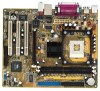
...You may configure two hard disks to the UltraDMA133/100 master device. SEC_IDE PRI_IDE ® P4VP-MX NOTE: Orient the red markings on the UltraDMA cable connector. Front panel audio connector (10-1 pin AUDIO1) This is recommended that allow convenient connection and control ...of audio devices. ® P4VP-MX AUDIO1 MIC2 MICPWR Line out_R NC Line out_L AGND +5VA BLINE_OUT_R BLINE_OUT_L P4VP-MX Front Panel Audio Connector 1-18 Chapter 1: Product introduction Pin 20 on each IDE connector is intentional...
...You may configure two hard disks to the UltraDMA133/100 master device. SEC_IDE PRI_IDE ® P4VP-MX NOTE: Orient the red markings on the UltraDMA cable connector. Front panel audio connector (10-1 pin AUDIO1) This is recommended that allow convenient connection and control ...of audio devices. ® P4VP-MX AUDIO1 MIC2 MICPWR Line out_R NC Line out_L AGND +5VA BLINE_OUT_R BLINE_OUT_L P4VP-MX Front Panel Audio Connector 1-18 Chapter 1: Product introduction Pin 20 on each IDE connector is intentional...

Motherboard DIY Troubleshooting Guide
Page 30
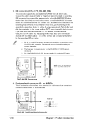
..., interactive gaming, and simultaneous running of the power LED connector in the system panel. ® P4VP-MX P4VP-MX Power LED PLED1 PLEDNC PLED+ 1 8. This speed advantage over the conventional 12 Mbps on the rear panel are inadequate, two USB headers are available for additional USB ports. USB+5V ... the system power LED. You must install the driver before you can use this header. USB+5V USB_P4USB_P4+ GND NC ® P4VP-MX P4VP-MX USB Header USB56 1 The USB2.0 module is purchased separately. System Power LED connector (3-pin PLED1) This 3-pin connector connects to this...
..., interactive gaming, and simultaneous running of the power LED connector in the system panel. ® P4VP-MX P4VP-MX Power LED PLED1 PLEDNC PLED+ 1 8. This speed advantage over the conventional 12 Mbps on the rear panel are inadequate, two USB headers are available for additional USB ports. USB+5V ... the system power LED. You must install the driver before you can use this header. USB+5V USB_P4USB_P4+ GND NC ® P4VP-MX P4VP-MX USB Header USB56 1 The USB2.0 module is purchased separately. System Power LED connector (3-pin PLED1) This 3-pin connector connects to this...

Motherboard DIY Troubleshooting Guide
Page 32
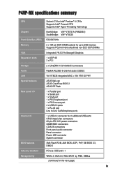
... up . • ATX Power Switch / Soft-Off Switch Lead (2-pin PWR BTN) This connector connects a switch that controls the system power. Ground Reset ® P4VP-MX PANEL1 P4VP-MX Front Panel Audio Connector IDE_LED Reset SW * Requires an ATX power supply. • System Power LED Lead (2-pin PWR LED) This 2-1 pin connector connects to the...
... up . • ATX Power Switch / Soft-Off Switch Lead (2-pin PWR BTN) This connector connects a switch that controls the system power. Ground Reset ® P4VP-MX PANEL1 P4VP-MX Front Panel Audio Connector IDE_LED Reset SW * Requires an ATX power supply. • System Power LED Lead (2-pin PWR LED) This 2-1 pin connector connects to the...

Motherboard DIY Troubleshooting Guide
Page 34
...CD. Copy the original (or the latest) motherboard BIOS to the bootable floppy disk. 2.1.2 Using AFUDOS to complete the process. 2. Visit the ASUS website (www.asus.com) to download the latest BIOS file for this motherboard is in DOS environment. 1. You need to restore the BIOS in case you copied... to a bootable floppy disk. Boot the system from the Control Panel window. At the DOS prompt, type the command line: afudos /i where "filename.rom...
...CD. Copy the original (or the latest) motherboard BIOS to the bootable floppy disk. 2.1.2 Using AFUDOS to complete the process. 2. Visit the ASUS website (www.asus.com) to download the latest BIOS file for this motherboard is in DOS environment. 1. You need to restore the BIOS in case you copied... to a bootable floppy disk. Boot the system from the Control Panel window. At the DOS prompt, type the command line: afudos /i where "filename.rom...
P4VP-MX user's manual English version E1538
Page 9
P4VP-MX specifications summary CPU Socket 478 for Intel® ...133/100/66/33 connectors Audio Realtek ALC655 6-channel audio CODEC LAN VIA VT8235 integrated MAC + VIA VT6103 PHY Special features ASUS MyLogo ASUS CrashFree BIOS 2 ASUS EZ Flash Rear panel I/O 1 x Parallel port 1 x Serial port 1 x VGA port 1 x PS/2 keyboard port 1 x PS/2 ... USB ports CPU/Chassis fan connectors 20-pin ATX 12V power connectors GAME/MIDI connectors CD/AUX connectors Front panel audio connector Panel connector Power LED connector System connector BIOS features 3Mb Flash ROM, AMI BIOS, ACPI, PnP, SM BIOS ...
P4VP-MX specifications summary CPU Socket 478 for Intel® ...133/100/66/33 connectors Audio Realtek ALC655 6-channel audio CODEC LAN VIA VT8235 integrated MAC + VIA VT6103 PHY Special features ASUS MyLogo ASUS CrashFree BIOS 2 ASUS EZ Flash Rear panel I/O 1 x Parallel port 1 x Serial port 1 x VGA port 1 x PS/2 keyboard port 1 x PS/2 ... USB ports CPU/Chassis fan connectors 20-pin ATX 12V power connectors GAME/MIDI connectors CD/AUX connectors Front panel audio connector Panel connector Power LED connector System connector BIOS features 3Mb Flash ROM, AMI BIOS, ACPI, PnP, SM BIOS ...

P4VP-MX user's manual English version E1538
Page 28
...for the secondary IDE connector. 1. BIOS supports specific device bootup. SEC_IDE PRI_IDE ® P4VP-MX NOTE: Orient the red markings on each IDE connector is intentional. 3. Front panel audio connector (10-1 pin AUDIO1) This is recommended that allow convenient connection and control... of audio devices. ® P4VP-MX AUDIO1 MIC2 MICPWR Line out_R NC Line out_L AGND +5VA BLINE_OUT_R BLINE_OUT_L P4VP-MX Front Panel Audio Connector 1-18 Chapter 1: Product introduction 3. one for the jumper settings. For ...
...for the secondary IDE connector. 1. BIOS supports specific device bootup. SEC_IDE PRI_IDE ® P4VP-MX NOTE: Orient the red markings on each IDE connector is intentional. 3. Front panel audio connector (10-1 pin AUDIO1) This is recommended that allow convenient connection and control... of audio devices. ® P4VP-MX AUDIO1 MIC2 MICPWR Line out_R NC Line out_L AGND +5VA BLINE_OUT_R BLINE_OUT_L P4VP-MX Front Panel Audio Connector 1-18 Chapter 1: Product introduction 3. one for the jumper settings. For ...
P4VP-MX user's manual English version E1538
Page 30
...-1 pin USB56) If the USB ports on USB 1.1 allows faster Internet connection, interactive gaming, and simultaneous running of the power LED connector in the system panel. ® P4VP-MX P4VP-MX Power LED PLED1 PLEDNC PLED+ 1 8. You must install the driver before you can use this header. If your case supports a 3-pin connector, use the...
...-1 pin USB56) If the USB ports on USB 1.1 allows faster Internet connection, interactive gaming, and simultaneous running of the power LED connector in the system panel. ® P4VP-MX P4VP-MX Power LED PLED1 PLEDNC PLED+ 1 8. You must install the driver before you can use this header. If your case supports a 3-pin connector, use the...

P4VP-MX user's manual English version E1538
Page 32
... (10-1 pin PANEL1) This connector accommodates several system front panel functions. ATX Power Power LED Switch* PLED+ PLEDPWR GND IDE_LED+ IDE_LED- The read and write activities of any device connected to the primary or secondary ... up . • ATX Power Switch / Soft-Off Switch Lead (2-pin PWR BTN) This connector connects a switch that controls the system power. Ground Reset ® P4VP-MX PANEL1 P4VP-MX Front Panel Audio Connector IDE_LED Reset SW * Requires an ATX power supply. • System Power LED Lead (2-pin PWR LED) This 2-1 pin connector connects to the...
... (10-1 pin PANEL1) This connector accommodates several system front panel functions. ATX Power Power LED Switch* PLED+ PLEDPWR GND IDE_LED+ IDE_LED- The read and write activities of any device connected to the primary or secondary ... up . • ATX Power Switch / Soft-Off Switch Lead (2-pin PWR BTN) This connector connects a switch that controls the system power. Ground Reset ® P4VP-MX PANEL1 P4VP-MX Front Panel Audio Connector IDE_LED Reset SW * Requires an ATX power supply. • System Power LED Lead (2-pin PWR LED) This 2-1 pin connector connects to the...

P4VP-MX user's manual English version E1538
Page 34
...Disk... At the DOS prompt, type: format A:/S Windows environment a. Click on the Startup Disk tab, then on Add/Remove Programs icon from the Control Panel window. button. Insert a 1.44 MB floppy disk when prompted. Do either one of the update process. 2-2 Chapter 2: BIOS information d. Copy the ...Write down the BIOS file name to complete the process. 2. Copy the AFUDOS.EXE utility from the floppy disk. 4. Visit the ASUS website (www.asus.com) to the bootable floppy disk that you need to restore the BIOS in the support CD. 2.1 Managing and updating your BIOS ...
...Disk... At the DOS prompt, type: format A:/S Windows environment a. Click on the Startup Disk tab, then on Add/Remove Programs icon from the Control Panel window. button. Insert a 1.44 MB floppy disk when prompted. Do either one of the update process. 2-2 Chapter 2: BIOS information d. Copy the ...Write down the BIOS file name to complete the process. 2. Copy the AFUDOS.EXE utility from the floppy disk. 4. Visit the ASUS website (www.asus.com) to the bootable floppy disk that you need to restore the BIOS in the support CD. 2.1 Managing and updating your BIOS ...


