
P4V8X-X User Manual
Page 6
... not sure about the voltage of the electrical outlet you add a device. • Before connecting or removing signal cables from the motherboard, ensure that your power supply is broken, do not try to the correct voltage in any damage, contact your retailer. Do not place the product in ... is set to fix it , carefully read all the manuals that the power cables for the devices are unplugged before the signal cables are connected. Operation safety • Before installing the motherboard and adding devices on a stable surface. • If you detect any area where it may become wet...
... not sure about the voltage of the electrical outlet you add a device. • Before connecting or removing signal cables from the motherboard, ensure that your power supply is broken, do not try to the correct voltage in any damage, contact your retailer. Do not place the product in ... is set to fix it , carefully read all the manuals that the power cables for the devices are unplugged before the signal cables are connected. Operation safety • Before installing the motherboard and adding devices on a stable surface. • If you detect any area where it may become wet...
P4V8X-X User Manual
Page 12
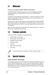
...world of system memory with the VIA® P4X533 chipset to set a new benchmark for buying the ASUS® P4V8X-X motherboard! The ASUS P4V8X-X motherboard delivers a host of new features and latest technologies making it , check the items in the long ...line of the above items is your P4V8X-X package for the Intel® next generation Prescott 533MHz FSB CPU. 1.1 Welcome! The CPU features the Intel Hyper-Threading Technology and a new power...
...world of system memory with the VIA® P4X533 chipset to set a new benchmark for buying the ASUS® P4V8X-X motherboard! The ASUS P4V8X-X motherboard delivers a host of new features and latest technologies making it , check the items in the long ...line of the above items is your P4V8X-X package for the Intel® next generation Prescott 533MHz FSB CPU. 1.1 Welcome! The CPU features the Intel Hyper-Threading Technology and a new power...
P4V8X-X User Manual
Page 13
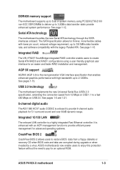
... non-ECC DDR DIMMs to deliver up to provide 6-channel audio playback for 5.1 surround sound and over 90dB dynamic range. ASUS P4V8X-X motherboard 1-3 Integrated RAID The VIA VT8237 SouthBridge integrated RAID controller enable users to 2.12GB/s. Integrated 10/100 LAN The onboard LAN ...controller is the next generation VGA interface specification that enables enhanced graphics performance with an ACPI management function to provide efficient power management for an easier and faster RAID installation and management. AGP 8X support AGP8X (AGP 3.0) is a highly integrated Fast ...
... non-ECC DDR DIMMs to deliver up to provide 6-channel audio playback for 5.1 surround sound and over 90dB dynamic range. ASUS P4V8X-X motherboard 1-3 Integrated RAID The VIA VT8237 SouthBridge integrated RAID controller enable users to 2.12GB/s. Integrated 10/100 LAN The onboard LAN ...controller is the next generation VGA interface specification that enables enhanced graphics performance with an ACPI management function to provide efficient power management for an easier and faster RAID installation and management. AGP 8X support AGP8X (AGP 3.0) is a highly integrated Fast ...
P4V8X-X User Manual
Page 15
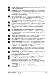
... using thin 4-conductor SATA cables. 9 South bridge controller. The chipset supports a highperformance floppy disk controller for the floppy disk drive. ASUS P4V8X-X motherboard 1-5 A 478-pin surface mount, Zero Insertion Force (ZIF) socket for 3D graphical applications. 8 SATA connectors. The VIA® ... AC'97 CODEC that supports AGP 3.0 specification including 8X Fast Write protocol. (* Overclocking mode) 4 DDR DIMM sockets. The power supply must have at 400/ 333/266MHz operation, and 1.5V/0.8V AGP interface that allows 6-channel audio playback. This connector accommodates...
... using thin 4-conductor SATA cables. 9 South bridge controller. The chipset supports a highperformance floppy disk controller for the floppy disk drive. ASUS P4V8X-X motherboard 1-5 A 478-pin surface mount, Zero Insertion Force (ZIF) socket for 3D graphical applications. 8 SATA connectors. The VIA® ... AC'97 CODEC that supports AGP 3.0 specification including 8X Fast Write protocol. (* Overclocking mode) 4 DDR DIMM sockets. The power supply must have at 400/ 333/266MHz operation, and 1.5V/0.8V AGP interface that allows 6-channel audio playback. This connector accommodates...
P4V8X-X User Manual
Page 18
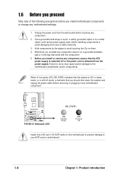
... to avoid damaging them . 4. Before you should shut down the system and unplug the power cable before touching any motherboard component. ® P4V8X-X P4V8X-X Onboard LED SB_PWR1 ON Standby Power OFF Powered Off Install only 0.8V and 1.5V AGP cards on a grounded antistatic pad or in... the bag that you install or remove any motherboard settings. 1. Failure to do so may cause severe ...
... to avoid damaging them . 4. Before you should shut down the system and unplug the power cable before touching any motherboard component. ® P4V8X-X P4V8X-X Onboard LED SB_PWR1 ON Standby Power OFF Powered Off Install only 0.8V and 1.5V AGP cards on a grounded antistatic pad or in... the bag that you install or remove any motherboard settings. 1. Failure to do so may cause severe ...
P4V8X-X User Manual
Page 19
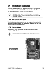
... into the holes indicated by circles to secure the motherboard to the chassis. Make sure to the rear part of the chassis as indicated in the correct orientation. Failure to ensure that...goes to unplug the power cord before installing or removing the motherboard. Do not overtighten the screws! Doing so may cause you physical injury and damage motherboard components. 1.7.1 Placement direction When installing the motherboard, make sure that you install the motherboard, study the configuration of the chassis ASUS P4V8X-X motherboard 1-9 1.7 Motherboard installation Before you ...
... into the holes indicated by circles to secure the motherboard to the chassis. Make sure to the rear part of the chassis as indicated in the correct orientation. Failure to ensure that...goes to unplug the power cord before installing or removing the motherboard. Do not overtighten the screws! Doing so may cause you physical injury and damage motherboard components. 1.7.1 Placement direction When installing the motherboard, make sure that you install the motherboard, study the configuration of the chassis ASUS P4V8X-X motherboard 1-9 1.7 Motherboard installation Before you ...
P4V8X-X User Manual
Page 22
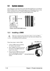
... DIMM. DIMM1 DIMM2 DIMM3 104 Pins 80 Pins ® P4V8X-X P4V8X-X 184-Pin DDR DIMM Sockets 1.9.1 Installing a DIMM Make sure to both the motherboard and the components. Failure to do so may cause severe damage to unplug the power supply before adding or removing DIMMs or other system components. ...1.9 System memory The motherboard comes with three Double Data Rate (DDR) Dual ...
... DIMM. DIMM1 DIMM2 DIMM3 104 Pins 80 Pins ® P4V8X-X P4V8X-X 184-Pin DDR DIMM Sockets 1.9.1 Installing a DIMM Make sure to both the motherboard and the components. Failure to do so may cause severe damage to unplug the power supply before adding or removing DIMMs or other system components. ...1.9 System memory The motherboard comes with three Double Data Rate (DDR) Dual ...
P4V8X-X User Manual
Page 27
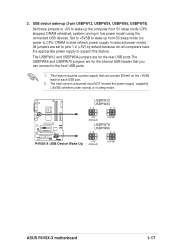
...Set these jumpers to +5V to CPU, DRAM in slow refresh, power supply in sleep mode. The total current consumed must NOT exceed the power supply capability (+5VSB) whether under normal or in reduced power mode). All jumpers are for the internal USB header that can ...5V) by default because not all computers have the appropriate power supply to the front USB ports. 1. USBPW12 USBPW34 12 23 +5V (Default) +5VSB ® P4V8X-X USBPW78 USBPW56 12 23 +5V P4V8X-X USB Device Wake Up (Default) +5VSB ASUS P4V8X-X motherboard 1-17 The USBPW12 and USBPW34 jumpers are for each USB ...
...Set these jumpers to +5V to CPU, DRAM in slow refresh, power supply in sleep mode. The total current consumed must NOT exceed the power supply capability (+5VSB) whether under normal or in reduced power mode). All jumpers are for the internal USB header that can ...5V) by default because not all computers have the appropriate power supply to the front USB ports. 1. USBPW12 USBPW34 12 23 +5V (Default) +5VSB ® P4V8X-X USBPW78 USBPW56 12 23 +5V P4V8X-X USB Device Wake Up (Default) +5VSB ASUS P4V8X-X motherboard 1-17 The USBPW12 and USBPW34 jumpers are for each USB ...
P4V8X-X User Manual
Page 30
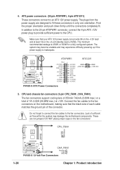
... +3.3VDC +3.3VDC +5.0VDC GND +5.0VDC +12V DC -5.0VDC COM COM COM PS_ON# COM -12.0VDC +3.3VDC GND +12V DC P4V8X-X ATX Power Connectors 5. The system may become unstable and may damage the motherboard components. Lack of 1A~2.22A (26.64W max.) at least 1A on the +5-volt standby lead (+5VSB). CPU_FAN1 GND +12V...
... +3.3VDC +3.3VDC +5.0VDC GND +5.0VDC +12V DC -5.0VDC COM COM COM PS_ON# COM -12.0VDC +3.3VDC GND +12V DC P4V8X-X ATX Power Connectors 5. The system may become unstable and may damage the motherboard components. Lack of 1A~2.22A (26.64W max.) at least 1A on the +5-volt standby lead (+5VSB). CPU_FAN1 GND +12V...
P4V8X-X User Manual
Page 33
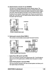
... When you to record a chassis intrusion event. CHASSIS1 +5VSB_MB Chassis Signal GND ® P4V8X-X P4V8X-X Chassis Alarm Lead (Default) 11. ASUS P4V8X-X motherboard 1-23 By default, the pins labeled "Chassis Signal" and "Ground" are shorted with ...intrusion detection feature. ExtSMI# Ground PWR Ground Reset Ground ® Reset SW P4V8X-X IDE_LED ATX Power SMI Lead Switch* * Requires an ATX power supply. The LED lights up when you turn on the system power...
... When you to record a chassis intrusion event. CHASSIS1 +5VSB_MB Chassis Signal GND ® P4V8X-X P4V8X-X Chassis Alarm Lead (Default) 11. ASUS P4V8X-X motherboard 1-23 By default, the pins labeled "Chassis Signal" and "Ground" are shorted with ...intrusion detection feature. ExtSMI# Ground PWR Ground Reset Ground ® Reset SW P4V8X-X IDE_LED ATX Power SMI Lead Switch* * Requires an ATX power supply. The LED lights up when you turn on the system power...
P4V8X-X User Manual
Page 39
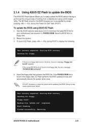
... If the P4V8XX.ROM file is built-in the drive, the error message "Floppy not found !" 4. Completed. Flashed successfully. ASUS P4V8X-X motherboard 2-5 Insert the floppy disk that contains the BIOS file. Doing so may cause system boot failure! Reading file "p4v8xx.rom". Start flashing...... P4V8XX.ROM. Reboot the system. 3. To launch EZ Flash, press + during the Power-On Self Tests (POST). To update the BIOS using a DOS-based utility. Visit the ASUS website (www.asus.com) to display the following. Checking for floppy... Checking for floppy... Rebooting. If ...
... If the P4V8XX.ROM file is built-in the drive, the error message "Floppy not found !" 4. Completed. Flashed successfully. ASUS P4V8X-X motherboard 2-5 Insert the floppy disk that contains the BIOS file. Doing so may cause system boot failure! Reading file "p4v8xx.rom". Start flashing...... P4V8XX.ROM. Reboot the system. 3. To launch EZ Flash, press + during the Power-On Self Tests (POST). To update the BIOS using a DOS-based utility. Visit the ASUS website (www.asus.com) to display the following. Checking for floppy... Checking for floppy... Rebooting. If ...
P4V8X-X User Manual
Page 42
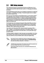
... program so that you to ensure system stability. It is designed to make your computer in the future. Visit the ASUS website (www.asus.com) to enable the security password feature or change the configuration of the firmware hub. This section explains how to configure...its test routines. See section "2.7 Exit Menu." Do this chapter are installing a motherboard, reconfiguring your system using the provided utility described in section "2.1 Managing and updating your screen. Press during the Power-On Self Test (POST) to use the Setup program, you may not exactly match...
... program so that you to ensure system stability. It is designed to make your computer in the future. Visit the ASUS website (www.asus.com) to enable the security password feature or change the configuration of the firmware hub. This section explains how to configure...its test routines. See section "2.7 Exit Menu." Do this chapter are installing a motherboard, reconfiguring your system using the provided utility described in section "2.1 Managing and updating your screen. Press during the Power-On Self Test (POST) to use the Setup program, you may not exactly match...
P4V8X-X User Manual
Page 43
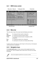
... has the following main items: Main Advanced Power Boot Exit For changing the basic system configuration For changing the advanced system settings For changing the advanced power management (APM) configuration For changing the system...select items in ] Primary IDE Master Primary IDE Slave Secondary IDE Master Secondary IDE Slave System Information :[ST320413A] :[ASUS CD-S340] :[Not Detected] :[Not Detected] Sub-menu items Use [ENTER], [TAB] or [SHIFT-TAB] ...27/2003] [1.44M, 3.5 in the menu and change the settings. ASUS P4V8X-X motherboard 2-9 Use [+] or [-] to select a field.
... has the following main items: Main Advanced Power Boot Exit For changing the basic system configuration For changing the advanced system settings For changing the advanced power management (APM) configuration For changing the system...select items in ] Primary IDE Master Primary IDE Slave Secondary IDE Master Secondary IDE Slave System Information :[ST320413A] :[ASUS CD-S340] :[Not Detected] :[Not Detected] Sub-menu items Use [ENTER], [TAB] or [SHIFT-TAB] ...27/2003] [1.44M, 3.5 in the menu and change the settings. ASUS P4V8X-X motherboard 2-9 Use [+] or [-] to select a field.
P4V8X-X User Manual
Page 57
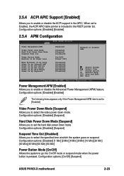
...to enable or disable the Advanced Power Management (APM) feature. Configuration options: [Disabled] [Suspend] Suspend Time Out [Disabled] Allows you to enable or disable the ACPI support in the RSDT pointer list. Configuration options: [On/Off] [Suspend] ASUS P4V8X-X motherboard 2-23 2.5.4 ACPI APIC Support [...Enabled] Allows you to select the specified time at which the system goes on AC Power Loss Wake Up/Power On by Ring Power On by Onboard LAN Power On by PCI Device Power On by RTC Alarm Power On by PS/2 Mouse Power On...
...to enable or disable the Advanced Power Management (APM) feature. Configuration options: [Disabled] [Suspend] Suspend Time Out [Disabled] Allows you to enable or disable the ACPI support in the RSDT pointer list. Configuration options: [On/Off] [Suspend] ASUS P4V8X-X motherboard 2-23 2.5.4 ACPI APIC Support [...Enabled] Allows you to select the specified time at which the system goes on AC Power Loss Wake Up/Power On by Ring Power On by Onboard LAN Power On by PCI Device Power On by RTC Alarm Power On by PS/2 Mouse Power On...

P4V8X-X User Manual
Page 59
If any of range, the following error message appears: "Hardware Monitor found an error. ASUS P4V8X-X motherboard 2-25 CPU Reference Voltage, +3.3V Voltage, +5V Voltage, +12V Voltage The onboard hardware monitor automatically detects the voltage output through the onboard ...monitored items is not connected to enter SETUP". You will then be prompted to "Press F1 to continue or DEL to the motherboard, the specific field shows N/A. Enter Power setup menu for details". CPU Fan Speed [xxxxRPM] or [N/A] Chassis Fan Speed [xxxxRPM] or [N/A] The onboard hardware monitor automatically...
If any of range, the following error message appears: "Hardware Monitor found an error. ASUS P4V8X-X motherboard 2-25 CPU Reference Voltage, +3.3V Voltage, +5V Voltage, +12V Voltage The onboard hardware monitor automatically detects the voltage output through the onboard ...monitored items is not connected to enter SETUP". You will then be prompted to "Press F1 to continue or DEL to the motherboard, the specific field shows N/A. Enter Power setup menu for details". CPU Fan Speed [xxxxRPM] or [N/A] Chassis Fan Speed [xxxxRPM] or [N/A] The onboard hardware monitor automatically...

P4V8X-X User Manual
Page 61
...the time needed to be pressed when error occurs. Configuration options: [Disabled] [Enabled] ASUS P4V8X-X motherboard 2-27 When set to Enabled, the system displays the message "Press DEL to skip some power on state for the NumLock. Change Option F1 General Help F10 Save and Exit ESC ... this item allows BIOS to run Setup" during POST. Configuration options: [Off] [On] PS/2 Mouse Support [Auto] Allows you to select the power-on self tests (POST) while booting to decrease the time needed to [Disabled] displays the normal POST messages. Configuration options: [Disabled] [Enabled]...
...the time needed to be pressed when error occurs. Configuration options: [Disabled] [Enabled] ASUS P4V8X-X motherboard 2-27 When set to Enabled, the system displays the message "Press DEL to skip some power on state for the NumLock. Change Option F1 General Help F10 Save and Exit ESC ... this item allows BIOS to run Setup" during POST. Configuration options: [Off] [On] PS/2 Mouse Support [Auto] Allows you to select the power-on self tests (POST) while booting to decrease the time needed to [Disabled] displays the normal POST messages. Configuration options: [Disabled] [Enabled]...
P4V8X-X User Manual
Page 69
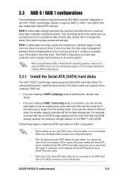
...and write data in the VIA® VT8237 southbridge chipset. Make sure the Master/Slave jumpers are configured properly. • Both the data and power SATA cables are creating a RAID 1 (mirroring) array for RAID configuration. • Before setting up your new RAID array, verify the status... creating RAID configurations. 3.3.1 Install the Serial ATA (SATA) hard disks The VIA® VT8237 southbridge chipset supports Serial ATA hard disk drives. ASUS P4V8X-X motherboard 3-5 If you use an existing drive and a new drive (the new drive must be of the data in the other hard disk has ...
...and write data in the VIA® VT8237 southbridge chipset. Make sure the Master/Slave jumpers are configured properly. • Both the data and power SATA cables are creating a RAID 1 (mirroring) array for RAID configuration. • Before setting up your new RAID array, verify the status... creating RAID configurations. 3.3.1 Install the Serial ATA (SATA) hard disks The VIA® VT8237 southbridge chipset supports Serial ATA hard disk drives. ASUS P4V8X-X motherboard 3-5 If you use an existing drive and a new drive (the new drive must be of the data in the other hard disk has ...
P4V8X-X User Manual
Page 70
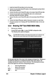
...RAID configuration utility. F1 Enter : ESC : View Array/Disk Status Move to the power connector on each menu item. VIA Tech. Connect the other end of the Serial ATA cable to the motherboard's secondary Serial ATA connector (SATA2). 5. The RAID BIOS information on your computer. 2....Serial_Ch1 Master XXXXXXXXXX Create a RAID array with their corresponding functions. Connect the other end of the second Serial ATA cable to the motherboard's primary Serial ATA connector (SATA1). 3. Proceed to navigate through the setup menu options. The keys on the legend box allows ...
...RAID configuration utility. F1 Enter : ESC : View Array/Disk Status Move to the power connector on each menu item. VIA Tech. Connect the other end of the Serial ATA cable to the motherboard's secondary Serial ATA connector (SATA2). 5. The RAID BIOS information on your computer. 2....Serial_Ch1 Master XXXXXXXXXX Create a RAID array with their corresponding functions. Connect the other end of the second Serial ATA cable to the motherboard's primary Serial ATA connector (SATA1). 3. Proceed to navigate through the setup menu options. The keys on the legend box allows ...


