Motherboard DIY Troubleshooting Guide
Page 46
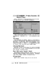
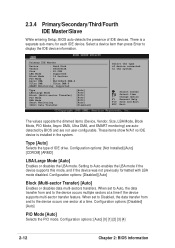
Change Option F1 General Help F10 Save and Exit ESC Exit 2-12 Primary IDE Master Device : Hard Disk Vendor : ST320413A Size : 20.0GB LBA Mode : Supported Block Mode : 16 Sectors PIO Mode : 4 Async DMA : MultiWord DMA-2 Ultra DMA : Ultra DMA-5 SMART Monitoring: Supported Type LBA/Large Mode Block (Multi-sector Transfer) PIO Mode DMA Mode Smart Monitoring 32Bit Data Transfer [Auto] [Auto] [Auto] [Auto] [Auto] [Auto] [Disabled] Select the type of device connected to the system. Select Screen Select Item +-
Change Option F1 General Help F10 Save and Exit ESC Exit 2-12 Primary IDE Master Device : Hard Disk Vendor : ST320413A Size : 20.0GB LBA Mode : Supported Block Mode : 16 Sectors PIO Mode : 4 Async DMA : MultiWord DMA-2 Ultra DMA : Ultra DMA-5 SMART Monitoring: Supported Type LBA/Large Mode Block (Multi-sector Transfer) PIO Mode DMA Mode Smart Monitoring 32Bit Data Transfer [Auto] [Auto] [Auto] [Auto] [Auto] [Auto] [Disabled] Select the type of device connected to the system. Select Screen Select Item +-
Motherboard DIY Troubleshooting Guide
Page 49
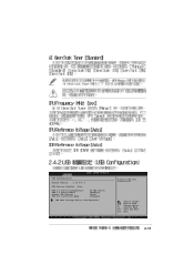
Change Option F1 General Help F10 Save and Exit ESC Exit 2-15 Select Screen Select Item +- USB Configuration Module Version : 2.22.4-5.3 USB Devices Enabled : None USB 1.1 Ports Configuration USB 2.0 Ports Enable Legacy USB Support USB 2.0 Controller Mode [8 USB Ports] [Enabled] [Auto] [HiSpeed] USB Mass Storage Device Configuration Enables USB host controllers.
Change Option F1 General Help F10 Save and Exit ESC Exit 2-15 Select Screen Select Item +- USB Configuration Module Version : 2.22.4-5.3 USB Devices Enabled : None USB 1.1 Ports Configuration USB 2.0 Ports Enable Legacy USB Support USB 2.0 Controller Mode [8 USB Ports] [Enabled] [Auto] [HiSpeed] USB Mass Storage Device Configuration Enables USB host controllers.
P4V8X-X User Manual
Page 12
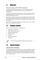
... list below. 1.2 Package contents Check your P4V8X-X package for the following items. ASUS P4V8X-X motherboard ASUS P4V8X-X series support CD UltraDMA 133/100/66 cable Floppy disk cable I/O shield Bag of extra jumper caps User Guide If any of the above items is damaged or missing, contact your affordable vehicle to 3GB of system memory with PC3200/2700/2100 DDR SDRAM, high-resolution graphics via an AGP 8X slot, Serial ATA support, USB...
... list below. 1.2 Package contents Check your P4V8X-X package for the following items. ASUS P4V8X-X motherboard ASUS P4V8X-X series support CD UltraDMA 133/100/66 cable Floppy disk cable I/O shield Bag of extra jumper caps User Guide If any of the above items is damaged or missing, contact your affordable vehicle to 3GB of system memory with PC3200/2700/2100 DDR SDRAM, high-resolution graphics via an AGP 8X slot, Serial ATA support, USB...
P4V8X-X User Manual
Page 13
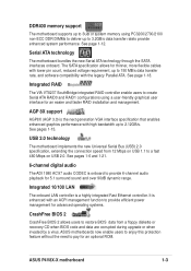
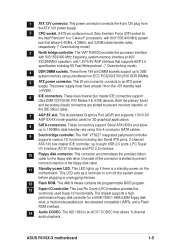
... 2.12GB/s. USB 2.0 technology The motherboard implements the new Universal Serial Bus (USB) 2.0 specification, extending the connection speed from a floppy diskette or recovery CD when BIOS code and data are corrupted during upgrade or when invaded by a virus. ASUS P4V8X-X motherboard 1-3 AGP 8X support AGP8X (AGP 3.0) is enhanced with the legacy Parallel ATA. See page 1-12. Integrated RAID The VIA VT8237 SouthBridge integrated RAID controller enable users to create Serial ATA RAID0 and RAID1 configurations using PC3200/2700...
... 2.12GB/s. USB 2.0 technology The motherboard implements the new Universal Serial Bus (USB) 2.0 specification, extending the connection speed from a floppy diskette or recovery CD when BIOS code and data are corrupted during upgrade or when invaded by a virus. ASUS P4V8X-X motherboard 1-3 AGP 8X support AGP8X (AGP 3.0) is enhanced with the legacy Parallel ATA. See page 1-12. Integrated RAID The VIA VT8237 SouthBridge integrated RAID controller enable users to create Serial ATA RAID0 and RAID1 configurations using PC3200/2700...
P4V8X-X User Manual
Page 15
... drive. These connectors support Serial ATA HDDs and allow up if there is slotted to an ATX power supply. This power connector connects the 4-pin 12V plug from the ATX 12V power supply. 2 CPU socket. This LED lights up to turn off the system power before plugging or unplugging devices. 12 Flash ROM. 1 ATX 12V connector. A 478-pin surface mount, Zero Insertion Force (ZIF) socket for a 360K/720K/1.44M/2.88M floppy disk drive, a multi-mode parallel port, two standard compatible UARTs, and a Flash ROM interface. 14 Audio CODEC. These dual-channel bus master IDE connectors support...
... drive. These connectors support Serial ATA HDDs and allow up if there is slotted to an ATX power supply. This power connector connects the 4-pin 12V plug from the ATX 12V power supply. 2 CPU socket. This LED lights up to turn off the system power before plugging or unplugging devices. 12 Flash ROM. 1 ATX 12V connector. A 478-pin surface mount, Zero Insertion Force (ZIF) socket for a 360K/720K/1.44M/2.88M floppy disk drive, a multi-mode parallel port, two standard compatible UARTs, and a Flash ROM interface. 14 Audio CODEC. These dual-channel bus master IDE connectors support...
P4V8X-X User Manual
Page 24
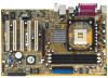
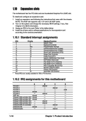
...) 5* 13 Sound card (sometimes LPT2) 6 14 Floppy Disk Controller 7* 15 Printer Port (LPT1) 8 3 System CMOS/Real Time Clock 9* 4 ACPI Mode when used PCI slot 4 shared - - - Onboard USB controller HC0 shared - - - Onboard USB controller HC3 - PCI slot 2 - - 1.10 Expansion slots The motherboard has five PCI slots and one Accelerated Graphics Port (AGP) slot. PCI slot 5 - Turn on the system and change the necessary BIOS settings, if any. Onboard audio - - NOTE: The AGP slot supports only 1.5V and 0.8V AGP cards. 2. Onboard USB 2.0 controller...
...) 5* 13 Sound card (sometimes LPT2) 6 14 Floppy Disk Controller 7* 15 Printer Port (LPT1) 8 3 System CMOS/Real Time Clock 9* 4 ACPI Mode when used PCI slot 4 shared - - - Onboard USB controller HC0 shared - - - Onboard USB controller HC3 - PCI slot 2 - - 1.10 Expansion slots The motherboard has five PCI slots and one Accelerated Graphics Port (AGP) slot. PCI slot 5 - Turn on the system and change the necessary BIOS settings, if any. Onboard audio - - NOTE: The AGP slot supports only 1.5V and 0.8V AGP cards. 2. Onboard USB 2.0 controller...
P4V8X-X User Manual
Page 29
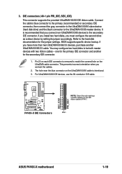
... IDE ribbon cable. If you install two hard disks, you connect non-UltraDMA100/66 devices to match the covered hole on the UltraDMA cable connector. The hole near the blue connector on the UltraDMA100/66 cable is removed to the secondary IDE connector. BIOS supports specific device bootup. You may configure two hard disks to the UltraDMA100/66 master device. 3. Pin 20 on the IDE ribbon cable to the hard disk documentation for the jumper settings. PIN 1 ASUS P4V8X-X motherboard 1-19 Connect the cable's blue connector...
... IDE ribbon cable. If you install two hard disks, you connect non-UltraDMA100/66 devices to match the covered hole on the UltraDMA cable connector. The hole near the blue connector on the UltraDMA100/66 cable is removed to the secondary IDE connector. BIOS supports specific device bootup. You may configure two hard disks to the UltraDMA100/66 master device. 3. Pin 20 on the IDE ribbon cable to the hard disk documentation for the jumper settings. PIN 1 ASUS P4V8X-X motherboard 1-19 Connect the cable's blue connector...
P4V8X-X User Manual
Page 33
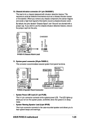
... ® P4V8X-X P4V8X-X Chassis Alarm Lead (Default) 11. ASUS P4V8X-X motherboard 1-23 By default, the pins labeled "Chassis Signal" and "Ground" are shorted with intrusion detection feature. ExtSMI# Ground PWR Ground Reset Ground ® Reset SW P4V8X-X IDE_LED ATX Power SMI Lead Switch* * Requires an ATX power supply. System panel connector (20-pin PANEL1) This connector accommodates several system front panel functions. When you to record a chassis intrusion event. If you wish to the system power LED. 10.
... ® P4V8X-X P4V8X-X Chassis Alarm Lead (Default) 11. ASUS P4V8X-X motherboard 1-23 By default, the pins labeled "Chassis Signal" and "Ground" are shorted with intrusion detection feature. ExtSMI# Ground PWR Ground Reset Ground ® Reset SW P4V8X-X IDE_LED ATX Power SMI Lead Switch* * Requires an ATX power supply. System panel connector (20-pin PANEL1) This connector accommodates several system front panel functions. When you to record a chassis intrusion event. If you wish to the system power LED. 10.
P4V8X-X User Manual
Page 36
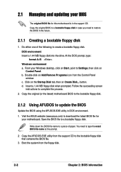
... MB floppy disk when prompted. Visit the ASUS website (www.asus.com) to download the latest BIOS file for this motherboard is in case you need to type the exact BIOS file name at the prompt. 2. Boot the system from the floppy disk. 2-2 Chapter 2: BIOS information From your motherboard. Save the BIOS file to a bootable floppy disk. 2.1 Managing and updating your BIOS The original BIOS file for your Windows desktop, click on Start, point to Settings, then click on Control Panel...
... MB floppy disk when prompted. Visit the ASUS website (www.asus.com) to download the latest BIOS file for this motherboard is in case you need to type the exact BIOS file name at the prompt. 2. Boot the system from the floppy disk. 2-2 Chapter 2: BIOS information From your motherboard. Save the BIOS file to a bootable floppy disk. 2.1 Managing and updating your BIOS The original BIOS file for your Windows desktop, click on Start, point to Settings, then click on Control Panel...
P4V8X-X User Manual
Page 44
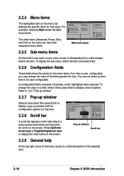
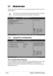
... screen. A configurable field is enclosed in brackets, and is user- Advanced PCI/PnP settings WARNING: Setting wrong values in the sections below may change the value of a field, select it then press Enter to configure system time. Press Up/Down arrow keys or PageUp/PageDown keys to display the other items (Advanced, Power, Boot, and Exit) on the menu bar have their respective menu items. Main menu items Use [ENTER...
... screen. A configurable field is enclosed in brackets, and is user- Advanced PCI/PnP settings WARNING: Setting wrong values in the sections below may change the value of a field, select it then press Enter to configure system time. Press Up/Down arrow keys or PageUp/PageDown keys to display the other items (Advanced, Power, Boot, and Exit) on the menu bar have their respective menu items. Main menu items Use [ENTER...
P4V8X-X User Manual
Page 46
... a device item then press Enter to Auto enables the LBA mode if the device supports this mode, and if the device was not previously formatted with LBA mode disabled. Change Option F1 General Help F10 Save and Exit ESC Exit The values opposite the dimmed items (Device, Vendor, Size, LBA Mode, Block Mode, PIO Mode, Async DMA, Ultra DMA, and SMART monitoring) are autodetected by BIOS and are not user-configurable. When set to Disabled...
... a device item then press Enter to Auto enables the LBA mode if the device supports this mode, and if the device was not previously formatted with LBA mode disabled. Change Option F1 General Help F10 Save and Exit ESC Exit The values opposite the dimmed items (Device, Vendor, Size, LBA Mode, Block Mode, PIO Mode, Async DMA, Ultra DMA, and SMART monitoring) are autodetected by BIOS and are not user-configurable. When set to Disabled...
P4V8X-X User Manual
Page 48
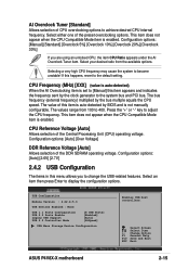
... Configure System Frequency/Voltage CPU Compatible Mode AI Overclock Tuner CPU Reference Voltage DDR Reference Voltage [Disabled] [Standard] [Auto] [Auto] If your system becomes unstable when overclocking with an 800MHz Front Side Bus CPU, enable this item to lower the FSB frequency by lowering the FSB frequency. If your system becomes unstable when using an 800MHz FSB CPU, enable this item for the CPU and other system devices. Select Screen Select Item +- JumperFree Configuration USB Configuration CPU Configuration Chipset Onboard Devices Configuration PCI PnP Configure...
... Configure System Frequency/Voltage CPU Compatible Mode AI Overclock Tuner CPU Reference Voltage DDR Reference Voltage [Disabled] [Standard] [Auto] [Auto] If your system becomes unstable when overclocking with an 800MHz Front Side Bus CPU, enable this item to lower the FSB frequency by lowering the FSB frequency. If your system becomes unstable when using an 800MHz FSB CPU, enable this item for the CPU and other system devices. Select Screen Select Item +- JumperFree Configuration USB Configuration CPU Configuration Chipset Onboard Devices Configuration PCI PnP Configure...
P4V8X-X User Manual
Page 49
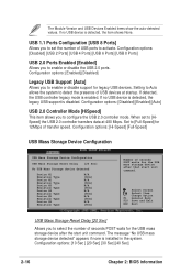
... Devices Enabled : None USB 1.1 Ports Configuration USB 2.0 Ports Enable Legacy USB Support USB 2.0 Controller Mode [8 USB Ports] [Enabled] [Auto] [HiSpeed] USB Mass Storage Device Configuration Enables USB host controllers. Select either one of the DDR SDRAM operating voltage. The bus frequency (external frequency) multiplied by the clock generator to change the USB-related features. Selecting a very high CPU frequency may cause the system to adjust the CPU frequency. Select Screen Select Item +- Change Option F1 General Help F10 Save and Exit ESC Exit ASUS P4V8X-X motherboard...
... Devices Enabled : None USB 1.1 Ports Configuration USB 2.0 Ports Enable Legacy USB Support USB 2.0 Controller Mode [8 USB Ports] [Enabled] [Auto] [HiSpeed] USB Mass Storage Device Configuration Enables USB host controllers. Select either one of the DDR SDRAM operating voltage. The bus frequency (external frequency) multiplied by the clock generator to change the USB-related features. Selecting a very high CPU frequency may cause the system to adjust the CPU frequency. Select Screen Select Item +- Change Option F1 General Help F10 Save and Exit ESC Exit ASUS P4V8X-X motherboard...
P4V8X-X User Manual
Page 50
... "No USB mass storage device detected" appears if none is enabled. Change Option F1 General Help F10 Save and Exit ESC Exit USB Mass Storage Reset Delay [20 Sec] Allows you to select the number of seconds POST waits for the USB mass storage device after that start unit command. Configuration options: [Disabled] [Enabled] [Auto] USB 2.0 Controller Mode [HiSpeed] This item allows you to configure the USB 2.0 controller mode. If no USB device is detected, the legacy USB support is detected...
... "No USB mass storage device detected" appears if none is enabled. Change Option F1 General Help F10 Save and Exit ESC Exit USB Mass Storage Reset Delay [20 Sec] Allows you to select the number of seconds POST waits for the USB mass storage device after that start unit command. Configuration options: [Disabled] [Enabled] [Auto] USB 2.0 Controller Mode [HiSpeed] This item allows you to configure the USB 2.0 controller mode. If no USB device is detected, the legacy USB support is detected...
P4V8X-X User Manual
Page 53
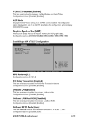
...the PCI Delay Transaction feature. Graphics Aperture Size [64MB] Allows you to auto-detect the onboard AC'97 audio CODEC. Configuration options: [Disabled] [Enabled] OnBoard LAN Boot ROM [Disabled] This item enables or disables the onboard LAN Boot ROM. Configuration options: [Disabled] [Auto] ASUS P4V8X-X motherboard 2-19 If an AGP8X card is installed, the configuration options display [4X] [2X] [1X] modes. Configuration options: [Disabled] [Enabled] OnBoard AC'97 Audio [Auto] This item disables or set to select the size of mapped memory for AGP graphic data. V-Link 8X Supported...
...the PCI Delay Transaction feature. Graphics Aperture Size [64MB] Allows you to auto-detect the onboard AC'97 audio CODEC. Configuration options: [Disabled] [Enabled] OnBoard LAN Boot ROM [Disabled] This item enables or disables the onboard LAN Boot ROM. Configuration options: [Disabled] [Auto] ASUS P4V8X-X motherboard 2-19 If an AGP8X card is installed, the configuration options display [4X] [2X] [1X] modes. Configuration options: [Disabled] [Enabled] OnBoard AC'97 Audio [Auto] This item disables or set to select the size of mapped memory for AGP graphic data. V-Link 8X Supported...
P4V8X-X User Manual
Page 56
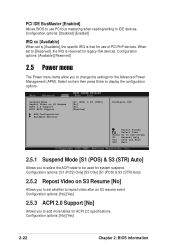
... resume event. Suspend Mode Repost Video on S3 Resume [No] Allows you to select the ACPI state to be used for use PCI bus mastering when reading/writing to IDE devices. Configuration options: [No] [Yes] 2-22 Chapter 2: BIOS information PCI IDE BusMaster [Enabled] Allows BIOS to use of PCI/PnP devices. Configuration options: [S1 (POS) Only] [S3 Only] [S1 (POS) & S3 (STR) Auto] 2.5.2 Repost Video on S3 Resume ACPI 2.0 Support ACPI APIC Support APM Configuration Hardware Monitor [S1 (POS...
... resume event. Suspend Mode Repost Video on S3 Resume [No] Allows you to select the ACPI state to be used for use PCI bus mastering when reading/writing to IDE devices. Configuration options: [No] [Yes] 2-22 Chapter 2: BIOS information PCI IDE BusMaster [Enabled] Allows BIOS to use of PCI/PnP devices. Configuration options: [S1 (POS) Only] [S3 Only] [S1 (POS) & S3 (STR) Auto] 2.5.2 Repost Video on S3 Resume ACPI 2.0 Support ACPI APIC Support APM Configuration Hardware Monitor [S1 (POS...
P4V8X-X User Manual
Page 66
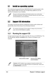
... version and corresponding updates so you can maximize the features of the support CD are subject to run the CD. 3-2 Chapter 3: Software support 3.1 Install an operating system This motherboard supports Windows 98SE/ME/2000/XP operating system (OS). Because motherboard settings and hardware options vary, use the setup procedures presented in your hardware. The CD automatically displays the Drivers menu if Autorun is NOT enabled in your CD-ROM drive...
... version and corresponding updates so you can maximize the features of the support CD are subject to run the CD. 3-2 Chapter 3: Software support 3.1 Install an operating system This motherboard supports Windows 98SE/ME/2000/XP operating system (OS). Because motherboard settings and hardware options vary, use the setup procedures presented in your hardware. The CD automatically displays the Drivers menu if Autorun is NOT enabled in your CD-ROM drive...
P4V8X-X User Manual
Page 67
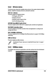
... Windows XP users, make sure to install WinXP Service Pack 1 to configure and manage disk drives. VIA PCI IRQ Miniport driver AD1980 SoundMAX Audio Driver This item installs the ADI 1980 AC'97 compliant audio controller and application. VIA 4 in 1 drivers This item installs the following drivers: - USB 2.0 Driver This item installs the USB 2.0 driver. VIA RAID Controller driver This item installs the VIA RAID controller driver and application to support USB 2.0. 3.2.3 Utilities menu The Utilities menu shows the applications and other software that the motherboard supports. ASUS P4V8X...
... Windows XP users, make sure to install WinXP Service Pack 1 to configure and manage disk drives. VIA PCI IRQ Miniport driver AD1980 SoundMAX Audio Driver This item installs the ADI 1980 AC'97 compliant audio controller and application. VIA 4 in 1 drivers This item installs the following drivers: - USB 2.0 Driver This item installs the USB 2.0 driver. VIA RAID Controller driver This item installs the VIA RAID controller driver and application to support USB 2.0. 3.2.3 Utilities menu The Utilities menu shows the applications and other software that the motherboard supports. ASUS P4V8X...
P4V8X-X User Manual
Page 68
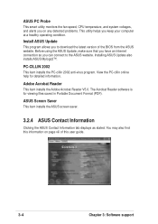
... Acrobat Reader V5.0. The Acrobat Reader software is for detailed information. ASUS PC Probe This smart utility monitors the fan speed, CPU temperature, and system voltages, and alerts you on page viii of the BIOS from the ASUS website. Installing ASUS Update also installs ASUS Mylogo2™. ASUS Screen Saver This item installs the ASUS screen saver. 3.2.4 ASUS Contact Information Clicking the ASUS Contact Information tab displays as stated. Install ASUS Update This program allows you keep your...
... Acrobat Reader V5.0. The Acrobat Reader software is for detailed information. ASUS PC Probe This smart utility monitors the fan speed, CPU temperature, and system voltages, and alerts you on page viii of the BIOS from the ASUS website. Installing ASUS Update also installs ASUS Mylogo2™. ASUS Screen Saver This item installs the ASUS screen saver. 3.2.4 ASUS Contact Information Clicking the ASUS Contact Information tab displays as stated. Install ASUS Update This program allows you keep your...
P4V8X-X User Manual
Page 70
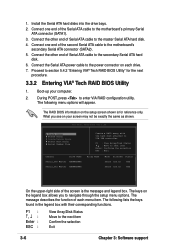
... the power connector on each menu item. What you to section 5.4.2 "Entering VIA® Tech RAID BIOS Utility" for reference only. The RAID BIOS information on your computer. 2. Connect the Serial ATA power cable to enter VIA RAID configuration utility. The following lists the keys found in the legend box with the hard disk attached to VIA IDE controller F1 : View Array/Disk Status , : Move to the next item Confirm the selection Exit 3-6 Chapter 3: Software support RAID BIOS...
... the power connector on each menu item. What you to section 5.4.2 "Entering VIA® Tech RAID BIOS Utility" for reference only. The RAID BIOS information on your computer. 2. Connect the Serial ATA power cable to enter VIA RAID configuration utility. The following lists the keys found in the legend box with the hard disk attached to VIA IDE controller F1 : View Array/Disk Status , : Move to the next item Confirm the selection Exit 3-6 Chapter 3: Software support RAID BIOS...


