User Manual
Page 1
® P4T-F Intel® 850 ATX Motherboard USER'S MANUAL
® P4T-F Intel® 850 ATX Motherboard USER'S MANUAL
User Manual
Page 2
... are represented by the third digit in any form or by any language in the manual revision number. Product Name: ASUS P4T-F Manual Revision: 1.01 E868 Release Date: September 2001 2 ASUS P4T-F User's Manual or (2) the serial number of the means indicated on the product itself. Manual revisions are registered trademarks of Microsoft Corporation. For previous or updated...
... are represented by the third digit in any form or by any language in the manual revision number. Product Name: ASUS P4T-F Manual Revision: 1.01 E868 Release Date: September 2001 2 ASUS P4T-F User's Manual or (2) the serial number of the means indicated on the product itself. Manual revisions are registered trademarks of Microsoft Corporation. For previous or updated...
User Manual
Page 3
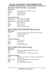
...) Notebook (Tel): +886-2-2890-7122 (English) Desktop/Server (Tel):+886-2-2890-7123 (English) Fax: +886-2-2890-7698 Email: tsd@asus.com.tw WWW: www.asus.com.tw FTP: ftp.asus.com.tw/pub/ASUS ASUS COMPUTER INTERNATIONAL (America) Marketing Address: 6737 Mowry Avenue, Mowry Business Center, Building 2 Newark, CA 94560, USA Fax: +1-510-608-4555... Fax: +49-2102-9599-11 Support (Email): www.asuscom.de/de/support (for online support) WWW: www.asuscom.de FTP: ftp.asuscom.de/pub/ASUSCOM ASUS P4T-F User's Manual 3
...) Notebook (Tel): +886-2-2890-7122 (English) Desktop/Server (Tel):+886-2-2890-7123 (English) Fax: +886-2-2890-7698 Email: tsd@asus.com.tw WWW: www.asus.com.tw FTP: ftp.asus.com.tw/pub/ASUS ASUS COMPUTER INTERNATIONAL (America) Marketing Address: 6737 Mowry Avenue, Mowry Business Center, Building 2 Newark, CA 94560, USA Fax: +1-510-608-4555... Fax: +49-2102-9599-11 Support (Email): www.asuscom.de/de/support (for online support) WWW: www.asuscom.de FTP: ftp.asuscom.de/pub/ASUSCOM ASUS P4T-F User's Manual 3
User Manual
Page 4
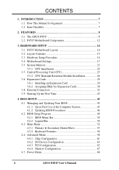
... Expansion Card 29 3.6.2 Assigning IRQs for Expansion Cards 30 3.8 External Connectors 32 3.9 Starting Up the First Time 43 4. INTRODUCTION 7 1.1 How This Manual Is Organized 7 1.2 Item Checklist 7 2. BIOS SETUP 45 4.1 Managing and Updating Your BIOS 45 4.1.1 Upon First Use of the Computer System 45 ... 4.4 Advanced Menu 58 4.4.1 Chip Configuration 61 4.4.2 I/O Device Configuration 63 4.4.3 PCI Configuration 65 4.4.4 Shadow Configuration 67 4.5 Power Menu 68 4 ASUS P4T-F User's Manual FEATURES 8 2.1 The ASUS P4T-F 8 2.2 P4T-F Motherboard Components 12 3. CONTENTS 1.
... Expansion Card 29 3.6.2 Assigning IRQs for Expansion Cards 30 3.8 External Connectors 32 3.9 Starting Up the First Time 43 4. INTRODUCTION 7 1.1 How This Manual Is Organized 7 1.2 Item Checklist 7 2. BIOS SETUP 45 4.1 Managing and Updating Your BIOS 45 4.1.1 Upon First Use of the Computer System 45 ... 4.4 Advanced Menu 58 4.4.1 Chip Configuration 61 4.4.2 I/O Device Configuration 63 4.4.3 PCI Configuration 65 4.4.4 Shadow Configuration 67 4.5 Power Menu 68 4 ASUS P4T-F User's Manual FEATURES 8 2.1 The ASUS P4T-F 8 2.2 P4T-F Motherboard Components 12 3. CONTENTS 1.
User Manual
Page 5
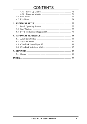
SOFTWARE SETUP 77 5.1 Install Operating System 77 5.2 Start Windows 77 5.3 P4T-F Motherboard Support CD 78 6. SOFTWARE REFERENCE 80 6.1 ASUS Live Update 80 6.2 ASUS PC Probe 81 6.3 CyberLink PowerPlayer SE 86 6.4 CyberLink VideoLive Mail 87 7. CONTENTS 4.5.1 Power Up Control 70 4.5.2 Hardware Monitor 71 4.6 Boot Menu 72 4.7 Exit Menu 74 5. APPENDIX 89 7.1 Glossary 89 INDEX 95 ASUS P4T-F User's Manual 5
SOFTWARE SETUP 77 5.1 Install Operating System 77 5.2 Start Windows 77 5.3 P4T-F Motherboard Support CD 78 6. SOFTWARE REFERENCE 80 6.1 ASUS Live Update 80 6.2 ASUS PC Probe 81 6.3 CyberLink PowerPlayer SE 86 6.4 CyberLink VideoLive Mail 87 7. CONTENTS 4.5.1 Power Up Control 70 4.5.2 Hardware Monitor 71 4.6 Boot Menu 72 4.7 Exit Menu 74 5. APPENDIX 89 7.1 Glossary 89 INDEX 95 ASUS P4T-F User's Manual 5
User Manual
Page 6
... Federal Regulations #47, part 15.193, 1993. Cet appareil numérique de la classe B est conforme à la norme NMB-003 du Canada. 6 ASUS P4T-F User's Manual Operation is subject to the following measures: • Re-orient or relocate the receiving antenna. • Increase the separation between the equipment and receiver. •...
... Federal Regulations #47, part 15.193, 1993. Cet appareil numérique de la classe B est conforme à la norme NMB-003 du Canada. 6 ASUS P4T-F User's Manual Operation is subject to the following measures: • Re-orient or relocate the receiving antenna. • Increase the separation between the equipment and receiver. •...
User Manual
Page 7
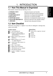
...damaged or missing items, contact your package is divided into the following sections: 1. INTRODUCTION Manual / Checklist 1. FEATURES 3. Package Contents (1) ASUS Motherboard (1) 40-pin 80-conductor ribbon cable for internal UltraDMA33/ 66/100 IDE drives (1)... drives (1) ASUS 2-port USB connector set with bracket (1) Bag of spare jumpers (1) Support drivers and utilities (1) This Motherboard User's Manual (1) CPU Retention Module (2) ASUS C-RIMM Continuity RIMM Optional Items ASUS IrDA-compliant infrared module Rambus LAN Card 1394 Card ASUS P4T-F User's Manual 7 SOFTWARE SETUP...
...damaged or missing items, contact your package is divided into the following sections: 1. INTRODUCTION Manual / Checklist 1. FEATURES 3. Package Contents (1) ASUS Motherboard (1) 40-pin 80-conductor ribbon cable for internal UltraDMA33/ 66/100 IDE drives (1)... drives (1) ASUS 2-port USB connector set with bracket (1) Bag of spare jumpers (1) Support drivers and utilities (1) This Motherboard User's Manual (1) CPU Retention Module (2) ASUS C-RIMM Continuity RIMM Optional Items ASUS IrDA-compliant infrared module Rambus LAN Card 1394 Card ASUS P4T-F User's Manual 7 SOFTWARE SETUP...

User Manual
Page 8
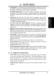
... Hub 2 (82801 ICH2) features support for UltraDMA/100, which allows burst mode data transfer rates of up to allow manual adjustment of 266MB/sec - twice the maximum bandwidth of 4 USB ports for the demanding PC user who wants advanced features... performance and multimedia and 3D functions, especially where high bandwidth is carefully designed for exceptiona peripheral connectivity options. 8 ASUS P4T-F User's Manual FEATURES 2.1 The ASUS P4T-F The ASUS P4T-F motherboard is required. • Intel® Accelerated Hub Architecture: Features a dedicated high speed hub link between the...
... Hub 2 (82801 ICH2) features support for UltraDMA/100, which allows burst mode data transfer rates of up to allow manual adjustment of 266MB/sec - twice the maximum bandwidth of 4 USB ports for the demanding PC user who wants advanced features... performance and multimedia and 3D functions, especially where high bandwidth is carefully designed for exceptiona peripheral connectivity options. 8 ASUS P4T-F User's Manual FEATURES 2.1 The ASUS P4T-F The ASUS P4T-F motherboard is required. • Intel® Accelerated Hub Architecture: Features a dedicated high speed hub link between the...
User Manual
Page 9
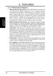
... memory and processor. • Onboard LED: Signals AC power is okay. • Desktop Management Interface (DMI): Supports DMI through the onboard hardware and the bundled ASUS PC Probe or Intel LDCM software. • Legacy Free: Provides five 32-bit PCI (PCI 2.2 compliant) with EPP and ECP capabilities. Supports Vcore and CPU....) 2.1.2 Optional Components • AC'97 Codec: The latest high-performance mini-chipset supports hi-fidelity 18-bit stereo, full duplex audio performance. FEATURES Optional Components 2. ASUS P4T-F User's Manual 9
... memory and processor. • Onboard LED: Signals AC power is okay. • Desktop Management Interface (DMI): Supports DMI through the onboard hardware and the bundled ASUS PC Probe or Intel LDCM software. • Legacy Free: Provides five 32-bit PCI (PCI 2.2 compliant) with EPP and ECP capabilities. Supports Vcore and CPU....) 2.1.2 Optional Components • AC'97 Codec: The latest high-performance mini-chipset supports hi-fidelity 18-bit stereo, full duplex audio performance. FEATURES Optional Components 2. ASUS P4T-F User's Manual 9
User Manual
Page 10
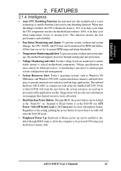
...Features for Windows 95/NT and later. To realize the benefits of the motherboard meet the stringent requirements for configuring and managing all ASUS smart series motherboards. UltraDMA/100 is backward compatible with DMA/66, DMA/33, and DMA and with two connectors that you do...UltraDMA/100/66, UltraDMA/33 (IDE DMA Mode 2), PIO Modes 3 & 4, and supports Enhanced IDE devices, such as required by PC 99. 10 ASUS P4T-F User's Manual While PC100 SDRAM modules operate at 100MHz with a peak bandwidth of 3.2GB/s. • ACPI Ready: ACPI (Advanced Configuration and Power Interface) is no...
...Features for Windows 95/NT and later. To realize the benefits of the motherboard meet the stringent requirements for configuring and managing all ASUS smart series motherboards. UltraDMA/100 is backward compatible with DMA/66, DMA/33, and DMA and with two connectors that you do...UltraDMA/100/66, UltraDMA/33 (IDE DMA Mode 2), PIO Modes 3 & 4, and supports Enhanced IDE devices, such as required by PC 99. 10 ASUS P4T-F User's Manual While PC100 SDRAM modules operate at 100MHz with a peak bandwidth of 3.2GB/s. • ACPI Ready: ACPI (Advanced Configuration and Power Interface) is no...
User Manual
Page 11
...can be enabled or disabled through BIOS setup to allow the computer to be powered ON using your keyboard or mouse click. ASUS P4T-F User's Manual 11 Suggestions will warn the user before the system resources are more critical for more memory and hard drive space to ensure ... are monitored to ensure stable current to prevent possible application crashes. The onboard hardware ASUS ASIC in 3.8 Connectors for future processors, so monitoring is enabled, the CPU with either the bundled ASUS PC Probe or Intel LDCM will give the user information on managing their limited resources...
...can be enabled or disabled through BIOS setup to allow the computer to be powered ON using your keyboard or mouse click. ASUS P4T-F User's Manual 11 Suggestions will warn the user before the system resources are more critical for more memory and hard drive space to ensure ... are monitored to ensure stable current to prevent possible application crashes. The onboard hardware ASUS ASIC in 3.8 Connectors for future processors, so monitoring is enabled, the CPU with either the bundled ASUS PC Probe or Intel LDCM will give the user information on managing their limited resources...
User Manual
Page 12
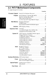
Location Processor Support Socket 423 for locations. FEATURES 2.2 P4T-F Motherboard Components See opposite page for Pentium 4 Processors 2 Chipsets Intel 850 Memory Controller Hub (MCH 4 Intel I/O Controller Hub 2 (ICH2 11 2Mbit Firmware Hub... 21 1 Game/MIDI Connector Top) 22 1 Line Out Connector Bottom) 22 1 Line In Connector Bottom) 22 1 Line Microphone Connector Bottom) 22 Hardware Monitoring ASUS onboard chipset 10 Power ATX Power Supply Connector 1 ATX 12V Power Supply Connector 3 Special Feature Auxillary Power Connector 6 Onboard LED 14 Form Factor ATX 12...
Location Processor Support Socket 423 for locations. FEATURES 2.2 P4T-F Motherboard Components See opposite page for Pentium 4 Processors 2 Chipsets Intel 850 Memory Controller Hub (MCH 4 Intel I/O Controller Hub 2 (ICH2 11 2Mbit Firmware Hub... 21 1 Game/MIDI Connector Top) 22 1 Line Out Connector Bottom) 22 1 Line In Connector Bottom) 22 1 Line Microphone Connector Bottom) 22 Hardware Monitoring ASUS onboard chipset 10 Power ATX Power Supply Connector 1 ATX 12V Power Supply Connector 3 Special Feature Auxillary Power Connector 6 Onboard LED 14 Form Factor ATX 12...
User Manual
Page 14
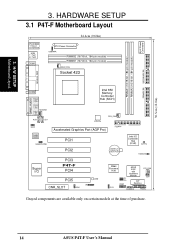
3. H/W SETUP Motherboard Layout 30.5cm (12.0in) AUX Power Connector 3. HARDWARE SETUP 3.1 P4T-F Motherboard Layout PS/2KBMS T: Mouse B: Keyboard USB T: Port1 B: Port2 COM1 24.4cm (9.60in) ATX Power Connector USBPWR RIMMB2 (16/18 bit, 184-pin module) ... Codec HEADPHONE PCI1 PCI2 CR2032 3V Lithium Cell CMOS Power Intel I/O Controller Hub (ICH2) CLRTC HDDLED Super I/O PCI3 P4T-F PCI4 PCI5 LED CNR_SLOT IR ADN 2Mbit Firmware Hub J3J3+ USB2 ASUS ASIC with Hardware Monitor PCI_FAN JEN DIP Switches OC3 CHASSIS PANEL Grayed components are available only on certain models at...
3. H/W SETUP Motherboard Layout 30.5cm (12.0in) AUX Power Connector 3. HARDWARE SETUP 3.1 P4T-F Motherboard Layout PS/2KBMS T: Mouse B: Keyboard USB T: Port1 B: Port2 COM1 24.4cm (9.60in) ATX Power Connector USBPWR RIMMB2 (16/18 bit, 184-pin module) ... Codec HEADPHONE PCI1 PCI2 CR2032 3V Lithium Cell CMOS Power Intel I/O Controller Hub (ICH2) CLRTC HDDLED Super I/O PCI3 P4T-F PCI4 PCI5 LED CNR_SLOT IR ADN 2Mbit Firmware Hub J3J3+ USB2 ASUS ASIC with Hardware Monitor PCI_FAN JEN DIP Switches OC3 CHASSIS PANEL Grayed components are available only on certain models at...
User Manual
Page 15
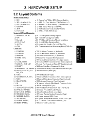
H/W SETUP Layout Contents 3. Selection (SW1 Switches 1-5) 3) SW1 (Switches 1-4) p. 20 Manual CPU Ratio Settings (SW1 Switches 7-10) 4) USBPWR p. 21 USB Device Wake-up (USBPWR) 5) ADN p. 22 Onboard Audio Codec (Enable/Disable) 6) J3-J3-/OC3 p. ... Switch Lead (2 pin) 23) PWRSW (PANEL) p.41 ATX Power / Soft-Off Switch Lead (2 pin) 24) RESET (PANEL) p.41 Reset Switch Lead (2 pin) ASUS P4T-F User's Manual 15 HARDWARE SETUP 3.2 Layout Contents Motherboard Settings 1) JEN p. 18 JumperFree™ Mode (JEN) (Disable / Enable) 2) SW1 (Switches 6-10) p. 19 CPU Ext. Freq. 3.
H/W SETUP Layout Contents 3. Selection (SW1 Switches 1-5) 3) SW1 (Switches 1-4) p. 20 Manual CPU Ratio Settings (SW1 Switches 7-10) 4) USBPWR p. 21 USB Device Wake-up (USBPWR) 5) ADN p. 22 Onboard Audio Codec (Enable/Disable) 6) J3-J3-/OC3 p. ... Switch Lead (2 pin) 23) PWRSW (PANEL) p.41 ATX Power / Soft-Off Switch Lead (2 pin) 24) RESET (PANEL) p.41 Reset Switch Lead (2 pin) ASUS P4T-F User's Manual 15 HARDWARE SETUP 3.2 Layout Contents Motherboard Settings 1) JEN p. 18 JumperFree™ Mode (JEN) (Disable / Enable) 2) SW1 (Switches 6-10) p. 19 CPU Ext. Freq. 3.
User Manual
Page 16
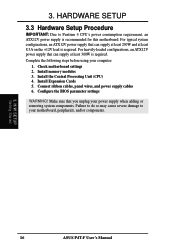
... adding or removing system components. Check motherboard settings 2. HARDWARE SETUP 3.3 Hardware Setup Procedure IMPORTANT: Due to your computer: 1. Install memory modules 3. H/W SETUP Getting Started 16 ASUS P4T-F User's Manual 3. Connect ribbon cables, panel wires, and power supply cables 6.
... adding or removing system components. Check motherboard settings 2. HARDWARE SETUP 3.3 Hardware Setup Procedure IMPORTANT: Due to your computer: 1. Install memory modules 3. H/W SETUP Getting Started 16 ASUS P4T-F User's Manual 3. Connect ribbon cables, panel wires, and power supply cables 6.

User Manual
Page 17
... components are separated from static electricity, you should follow some precautions whenever you how to touch the IC chips, leads or connectors, or other components. 4. P4T-F P4T-F Onboard LED ON Standby Power OFF Powered Off 3. HARDWARE SETUP 3.4 Motherboard Settings This section tells you work on the bag that the ATX power supply...
... components are separated from static electricity, you should follow some precautions whenever you how to touch the IC chips, leads or connectors, or other components. 4. P4T-F P4T-F Onboard LED ON Standby Power OFF Powered Off 3. HARDWARE SETUP 3.4 Motherboard Settings This section tells you work on the bag that the ATX power supply...
User Manual
Page 18
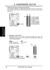
... Selection 9. 3. Frequency Multiple 4. Frequency Selection 8. Frequency Multiple 5. The JumperFree™ mode allows processor settings to enable or disable the JumperFree™ mode. P4T-F P4T-F DIP Switches ON 1 2 3 4 5 6 7 8 9 10 ON OFF SW1 1. Frequency Selection 7. Frequency Selection 3. Frequency Multiple 2. HARDWARE SETUP Motherboard... Setting JEN Enable (JumperFree) [2-3] (default) Disable (Jumper Mode) [1-2] JEN OFF SW1 ON 1 2 3 4 5 6 7 8 9 10 P4T-F 12 Jumper Mode P4T-F JumperFree™ Mode Setting 23 Jumper Free (Default) 18 ASUS P4T-F User's Manual
... Selection 9. 3. Frequency Multiple 4. Frequency Selection 8. Frequency Multiple 5. The JumperFree™ mode allows processor settings to enable or disable the JumperFree™ mode. P4T-F P4T-F DIP Switches ON 1 2 3 4 5 6 7 8 9 10 ON OFF SW1 1. Frequency Selection 7. Frequency Selection 3. Frequency Multiple 2. HARDWARE SETUP Motherboard... Setting JEN Enable (JumperFree) [2-3] (default) Disable (Jumper Mode) [1-2] JEN OFF SW1 ON 1 2 3 4 5 6 7 8 9 10 P4T-F 12 Jumper Mode P4T-F JumperFree™ Mode Setting 23 Jumper Free (Default) 18 ASUS P4T-F User's Manual
User Manual
Page 19
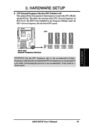
...Internal frequency (the advertised CPU speed). Set the CPU frequency only to the CPU, DRAM, and the PCI bus. H/W SETUP Motherboard Settings 3. ASUS P4T-F User's Manual 19 HARDWARE SETUP 2) CPU External Frequency Selection (SW1 Switches 6-10) This option tells the clock generator what frequency to send to the recommended ...). Frequencies other than the recommended CPU bus frequencies are not guaranteed to be stable. It may result in a slower speed. SW1 P4T-F P4T-F CPU External Frequency Selection CPU 100.0MHz 103.0MHz 105.0MHz 110.0MHz AGP 66.0MHz 68.0MHz 70.0MHz 73.0MHz PCI 33...
...Internal frequency (the advertised CPU speed). Set the CPU frequency only to the CPU, DRAM, and the PCI bus. H/W SETUP Motherboard Settings 3. ASUS P4T-F User's Manual 19 HARDWARE SETUP 2) CPU External Frequency Selection (SW1 Switches 6-10) This option tells the clock generator what frequency to send to the recommended ...). Frequencies other than the recommended CPU bus frequencies are not guaranteed to be stable. It may result in a slower speed. SW1 P4T-F P4T-F CPU External Frequency Selection CPU 100.0MHz 103.0MHz 105.0MHz 110.0MHz AGP 66.0MHz 68.0MHz 70.0MHz 73.0MHz PCI 33...
User Manual
Page 20
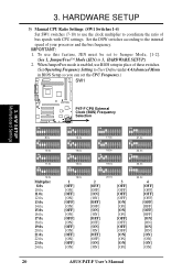
... 4.4 Advanced Menu in 3, HARDWARE SETUP.) 2. Set the DSW switches according to coordinate the ratio of your processor and the bus frequency. HARDWARE SETUP 3) Manual CPU Ratio Settings (SW1 Switches 1-4) Set SW1 switches (7-10) to use this feature, JEN must be set the CPU Frequency.) SW1 3. H/W SETUP Motherboard Settings...] [OFF] [OFF] [OFF] [ON] [ON] [ON] [ON] 4 [OFF] [OFF] [OFF] [OFF] [OFF] [OFF] [OFF] [OFF] [ON] [ON] [ON] [ON] [ON] [ON] [ON] [ON] 20 ASUS P4T-F User's Manual 3. To use the clock multiplier to the internal speed of bus speeds with CPU settings. IMPORTANT: 1.
... 4.4 Advanced Menu in 3, HARDWARE SETUP.) 2. Set the DSW switches according to coordinate the ratio of your processor and the bus frequency. HARDWARE SETUP 3) Manual CPU Ratio Settings (SW1 Switches 1-4) Set SW1 switches (7-10) to use this feature, JEN must be set the CPU Frequency.) SW1 3. H/W SETUP Motherboard Settings...] [OFF] [OFF] [OFF] [ON] [ON] [ON] [ON] 4 [OFF] [OFF] [OFF] [OFF] [OFF] [OFF] [OFF] [OFF] [ON] [ON] [ON] [ON] [ON] [ON] [ON] [ON] 20 ASUS P4T-F User's Manual 3. To use the clock multiplier to the internal speed of bus speeds with CPU settings. IMPORTANT: 1.
User Manual
Page 21
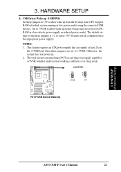
... power supply that can supply at least 2A on the +5VSB lead when these jumpers to +5V to +5VSB. RAM refreshed; H/W SETUP Motherboard Settings ASUS P4T-F User's Manual 21 The total current consumed must NOT exceed the power supply capability (+5VSB) whether under normal working conditions or in slow refresh; power supply in... 4) USB Device Wake-up (USBPWR) Set these jumpers are set to allow wake up from the S1 sleep state (CPU stopped; NOTES: 1. USBPWR 2 1 +5VSB 3 2 +5V P4T-F P4T-F USB Device Wake Up 3.
... power supply that can supply at least 2A on the +5VSB lead when these jumpers to +5V to +5VSB. RAM refreshed; H/W SETUP Motherboard Settings ASUS P4T-F User's Manual 21 The total current consumed must NOT exceed the power supply capability (+5VSB) whether under normal working conditions or in slow refresh; power supply in... 4) USB Device Wake-up (USBPWR) Set these jumpers are set to allow wake up from the S1 sleep state (CPU stopped; NOTES: 1. USBPWR 2 1 +5VSB 3 2 +5V P4T-F P4T-F USB Device Wake Up 3.


