
P4SE User Manual
Page 3
... more information vii ASUS contact information vii Specifications summary ix Chapter 1 - Features Contents Contents iii FCC/CDC statements v Federal Communications Commission Statement v Canadian Department of Communications Statement v Safety information vi About this guide vii Conventions used in this guide vii Where to update the BIOS 2-2 Updating BIOS procedures 2-3 2.2 BIOS Setup Program 2-5 2.2.1 BIOS menu bar 2-5 2.2.2 Legend...
... more information vii ASUS contact information vii Specifications summary ix Chapter 1 - Features Contents Contents iii FCC/CDC statements v Federal Communications Commission Statement v Canadian Department of Communications Statement v Safety information vi About this guide vii Conventions used in this guide vii Where to update the BIOS 2-2 Updating BIOS procedures 2-3 2.2 BIOS Setup Program 2-5 2.2.1 BIOS menu bar 2-5 2.2.2 Legend...

P4SE User Manual
Page 10
...P4SE specifications summary BIOS features 2Mb Flash EEPROM, ASUS JumperFree, ASUS MyLogo, Award BIOS with ACPI, DMI2.0, PnP, WfM2.0, Green, TCAV (Trend Chip Away Virus) Industry standard PCI 2.2, USB 1.1 Manageability WfM2.0, DMI2.0, WOR, WOL, Chassis Intrusion, SM Bus Form Factor ATX form factor: 12 in x 8.6 in (30.5 cm x 21.9 cm) Support CD contents Device drivers ASUS... PC Probe Trend Microtm PC-cillin 2002 anti-virus software ASUS LiveUpdate Utility Accessories User's manual Support CD 1 x UltraDMA 133/100/66 ...
...P4SE specifications summary BIOS features 2Mb Flash EEPROM, ASUS JumperFree, ASUS MyLogo, Award BIOS with ACPI, DMI2.0, PnP, WfM2.0, Green, TCAV (Trend Chip Away Virus) Industry standard PCI 2.2, USB 1.1 Manageability WfM2.0, DMI2.0, WOR, WOL, Chassis Intrusion, SM Bus Form Factor ATX form factor: 12 in x 8.6 in (30.5 cm x 21.9 cm) Support CD contents Device drivers ASUS... PC Probe Trend Microtm PC-cillin 2002 anti-virus software ASUS LiveUpdate Utility Accessories User's manual Support CD 1 x UltraDMA 133/100/66 ...
P4SE User Manual
Page 15
...provides the commonly used Super I /O chipset. This 25-pin port connects a parallel printer, a scanner, or other serial devices. 24 USB port. ASUS P4SE Motherboard 1-5 This green 6-pin connector is for a PS/2 keyboard. This port connects to turn off the system power before plugging or unplugging devices. ...serial port. 14 Standby power LED. The LED acts as a mouse and PDA. 25 PS/2 keyboard port. This 2Mb firmware contains the programmable BIOS program. 16 PCI slots. This Line Out (lime) jack connects a headphone or a speaker. 23 Serial port. This SiS 961B controller integrates the...
...provides the commonly used Super I /O chipset. This 25-pin port connects a parallel printer, a scanner, or other serial devices. 24 USB port. ASUS P4SE Motherboard 1-5 This green 6-pin connector is for a PS/2 keyboard. This port connects to turn off the system power before plugging or unplugging devices. ...serial port. 14 Standby power LED. The LED acts as a mouse and PDA. 25 PS/2 keyboard port. This 2Mb firmware contains the programmable BIOS program. 16 PCI slots. This Line Out (lime) jack connects a headphone or a speaker. 23 Serial port. This SiS 961B controller integrates the...

P4SE User Manual
Page 19
...the expansion card, configure the card by adjusting the software settings. 1. PCI slot 3 - - When using PCI cards on the system and change the necessary BIOS settings, if any. 2. The following subsections describe the slots and the expansion cards that the cards do not need IRQ assignments. shared - - PCI slot 4... IDE Channel 15* 10 Secondary IDE Channel *These IRQs are usually available for this motherboard ABCD PCI slot 1 shared - - - PCI slot 2 - ASUS P4SE Motherboard 1-9 shared PCI slot 5 shared - - - IRQ assignments for ISA or PCI devices. shared -
...the expansion card, configure the card by adjusting the software settings. 1. PCI slot 3 - - When using PCI cards on the system and change the necessary BIOS settings, if any. 2. The following subsections describe the slots and the expansion cards that the cards do not need IRQ assignments. shared - - PCI slot 4... IDE Channel 15* 10 Secondary IDE Channel *These IRQs are usually available for this motherboard ABCD PCI slot 1 shared - - - PCI slot 2 - ASUS P4SE Motherboard 1-9 shared PCI slot 5 shared - - - IRQ assignments for ISA or PCI devices. shared -

P4SE User Manual
Page 20
... white block represents the switch position. Frequency Selection 3. Frequency Selection 4. JEN1 OFF ON DSW1 ON 12345 P4SE ® 2 1 Jumper Mode P4SE JumperFree™ Mode Setting 3 2 Jumper Free (Default) The JEN jumper is adjusted through the BIOS setup instead of using the DIP switches. 1.9 Switches and jumpers The motherboard frequency is set all the...
... white block represents the switch position. Frequency Selection 3. Frequency Selection 4. JEN1 OFF ON DSW1 ON 12345 P4SE ® 2 1 Jumper Mode P4SE JumperFree™ Mode Setting 3 2 Jumper Free (Default) The JEN jumper is adjusted through the BIOS setup instead of using the DIP switches. 1.9 Switches and jumpers The motherboard frequency is set all the...

P4SE User Manual
Page 21
...100MHz DRAM 100MHz 133MHz 150MHz 160MHz 166MHz ON 12345 ON 12345 ON 12345 ON 12345 ON 12345 ON 12345 P4SE ® CPU 105MHz DRAM 140MHz P4SE CPU External Frequency Selection 108MHz 144MHz 112MHz 149MHz 133MHz 133MHz 133MHz 166MHz 100MHz 200MHz Set the CPU frequency ...frequency (or Bus Clock). Frequencies other than the recommended CPU bus frequencies are not guaranteed to jumper mode. P4SE ® KBPWR1 2 1 +5V 3 2 +5VSB (Default) P4SE Keyboard Power Setting ASUS P4SE Motherboard 1-11 This feature requires an ATX power supply that the JEN jumper is the Space Bar). Keyboard...
...100MHz DRAM 100MHz 133MHz 150MHz 160MHz 166MHz ON 12345 ON 12345 ON 12345 ON 12345 ON 12345 ON 12345 P4SE ® CPU 105MHz DRAM 140MHz P4SE CPU External Frequency Selection 108MHz 144MHz 112MHz 149MHz 133MHz 133MHz 133MHz 166MHz 100MHz 200MHz Set the CPU frequency ...frequency (or Bus Clock). Frequencies other than the recommended CPU bus frequencies are not guaranteed to jumper mode. P4SE ® KBPWR1 2 1 +5V 3 2 +5VSB (Default) P4SE Keyboard Power Setting ASUS P4SE Motherboard 1-11 This feature requires an ATX power supply that the JEN jumper is the Space Bar). Keyboard...
P4SE User Manual
Page 23
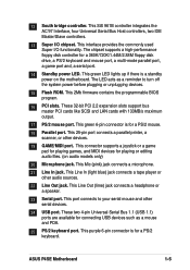
... erase the RTC RAM: 1. Replace the battery. 6. P4SE ® P4SE Clear RTC RAM ASUS P4SE Motherboard CLRCMOS1 2 1 Normal (Default) 3 2 Clear ...CMOS 1-13 Turn OFF the computer and unplug the power cord. 2. Remove the jumper cap from the CLRTC jumper, [1-2] and place it on jumpers [2-3] for adjusting the voltage. The other settings do not guarantee better system performance. P4SE... ® DDRVOL1 12 23 2.5V 2.7V (Default) 34 2.9V P4SE DDRVOL Setting 7. Replace the...
... erase the RTC RAM: 1. Replace the battery. 6. P4SE ® P4SE Clear RTC RAM ASUS P4SE Motherboard CLRCMOS1 2 1 Normal (Default) 3 2 Clear ...CMOS 1-13 Turn OFF the computer and unplug the power cord. 2. Remove the jumper cap from the CLRTC jumper, [1-2] and place it on jumpers [2-3] for adjusting the voltage. The other settings do not guarantee better system performance. P4SE... ® DDRVOL1 12 23 2.5V 2.7V (Default) 34 2.9V P4SE DDRVOL Setting 7. Replace the...

P4SE User Manual
Page 24
Refer to be both master devices with two ribbon cables - one for the jumper settings. SECONDARY IDE PRIMARY IDE P4SE ® P4SE IDE Connectors 1-14 NOTE: Orient the red markings (usually zigzag) on the UltraDMA/100/66 cable is intentional. ...Some pins are clearly distinguished from jumpers in the Motherboard Layout. IDE connectors (40-1 pin PRIMARY IDE/SECONDARY IDE) This connector supports the provided UltraDMA133/100/66 IDE hard disk ribbon cable. BIOS...
Refer to be both master devices with two ribbon cables - one for the jumper settings. SECONDARY IDE PRIMARY IDE P4SE ® P4SE IDE Connectors 1-14 NOTE: Orient the red markings (usually zigzag) on the UltraDMA/100/66 cable is intentional. ...Some pins are clearly distinguished from jumpers in the Motherboard Layout. IDE connectors (40-1 pin PRIMARY IDE/SECONDARY IDE) This connector supports the provided UltraDMA133/100/66 IDE hard disk ribbon cable. BIOS...

P4SE User Manual
Page 28
... monitoring feature, connect its thermal sensor cable to a small opening on system chassis that support this connector. IR 1 P4SE ® P4SE Infrared Module Connector +5V IRRX GND IRTX Front View Back View IRTX +5V GND (NC) IRRX 1-18 Chapter 1: Motherboard Information PWRTMP1... P4SE ® Power Supply Thermal Sensor P4SE Thermal Sensor Connector 9. This module mounts to this feature. Use the five pins as shown in BIOS to the pin definitions. Infrared module connector (two 5-1 pin IR) This...
... monitoring feature, connect its thermal sensor cable to a small opening on system chassis that support this connector. IR 1 P4SE ® P4SE Infrared Module Connector +5V IRRX GND IRTX Front View Back View IRTX +5V GND (NC) IRRX 1-18 Chapter 1: Motherboard Information PWRTMP1... P4SE ® Power Supply Thermal Sensor P4SE Thermal Sensor Connector 9. This module mounts to this feature. Use the five pins as shown in BIOS to the pin definitions. Infrared module connector (two 5-1 pin IR) This...

P4SE User Manual
Page 33
... a switch that controls the system power. Pressing the power switch turns the system between ON and SLEEP, or ON and SOFT OFF, depending on the BIOS or OS settings. Pressing the power switch while in the ON mode for rebooting the system without turning off the system power. • System Management... system into a suspend mode, or "green" mode, where system activity is instantly decreased to save power and to expand the life of certain system components. ASUS P4SE Motherboard 1-23
... a switch that controls the system power. Pressing the power switch turns the system between ON and SLEEP, or ON and SOFT OFF, depending on the BIOS or OS settings. Pressing the power switch while in the ON mode for rebooting the system without turning off the system power. • System Management... system into a suspend mode, or "green" mode, where system activity is instantly decreased to save power and to expand the life of certain system components. ASUS P4SE Motherboard 1-23

P4SE User Manual
Page 35
Chapter 2 This chapter gives information about the ASUS P4SE Binary Input/Output System (BIOS).This chapter includes updating the BIOS using the ASUS AFLASH BIOS that is bundled with the support CD. BIOS Information ASUS P4SE Motherboard 2-1
Chapter 2 This chapter gives information about the ASUS P4SE Binary Input/Output System (BIOS).This chapter includes updating the BIOS using the ASUS AFLASH BIOS that is bundled with the support CD. BIOS Information ASUS P4SE Motherboard 2-1

P4SE User Manual
Page 36
... the floppy disk. In DOS mode, type A:\AFLASH to create a bootable system disk. Reboot the computer from the hard drive. Larger numbers represent a newer BIOS file. 1. It is a Flash Memory Writer utility that you see on your screen may be programmed by the ACPI... only in the boot sequence. 4. AFLASH works only in the above screen is not supported by the Flash Memory Writer utility. 2-2 Chapter 2: BIOS Information To determine the BIOS version of your motherboard, check the last four numbers of your screen during bootup. DO NOT copy AUTOEXEC.BAT and CONFIG.SYS to...
... the floppy disk. In DOS mode, type A:\AFLASH to create a bootable system disk. Reboot the computer from the hard drive. Larger numbers represent a newer BIOS file. 1. It is a Flash Memory Writer utility that you see on your screen may be programmed by the ACPI... only in the boot sequence. 4. AFLASH works only in the above screen is not supported by the Flash Memory Writer utility. 2-2 Chapter 2: BIOS Information To determine the BIOS version of your motherboard, check the last four numbers of your screen during bootup. DO NOT copy AUTOEXEC.BAT and CONFIG.SYS to...

P4SE User Manual
Page 37
... to more problems with the motherboard! 1. ASUS P4SE Motherboard 2-3 Select 1. The Update BIOS Including Boot Block and ESCD screen appears. 5. At the "A:\" prompt, type AFLASH and then press . 4. At the Main Menu, type 2 then press . Updating the BIOS Update the BIOS only if you created earlier. 2. To ... menu and press . Type a filename and the path, for example, A:\XXX-XX.XXX, then press . 5. Download an updated ASUS BIOS file from the Internet (WWW or FTP) (see ASUS CONTACT INFORMATION on page x for details) and save to File from the floppy disk. 3. Save Current...
... to more problems with the motherboard! 1. ASUS P4SE Motherboard 2-3 Select 1. The Update BIOS Including Boot Block and ESCD screen appears. 5. At the "A:\" prompt, type AFLASH and then press . 4. At the Main Menu, type 2 then press . Updating the BIOS Update the BIOS only if you created earlier. 2. To ... menu and press . Type a filename and the path, for example, A:\XXX-XX.XXX, then press . 5. Download an updated ASUS BIOS file from the Internet (WWW or FTP) (see ASUS CONTACT INFORMATION on page x for details) and save to File from the floppy disk. 3. Save Current...

P4SE User Manual
Page 38
6. This may cause boot problems. Just repeat the process, and if the problem persists, load the original BIOS file you saved to successfully update a complete BIOS file, call the ASUS service center for support. 2-4 Chapter 2: BIOS Information When the programming is updated automatically only when necessary. If the Flash Memory Writer utility is not able...
6. This may cause boot problems. Just repeat the process, and if the problem persists, load the original BIOS file you saved to successfully update a complete BIOS file, call the ASUS service center for support. 2-4 Chapter 2: BIOS Information When the programming is updated automatically only when necessary. If the Flash Memory Writer utility is not able...

P4SE User Manual
Page 39
...the basic system configuration. Press during the Power-On Self Test (POST) to enter the Setup utility, otherwise, POST continues with the following BIOS setup screens and descriptions are installing a motherboard, reconfiguring your system, or prompted to "Run Setup". ADVANCED Use this utility. It is ...used to configure your screen. 2.2.1 BIOS menu bar The top of your computer in the CMOS RAM of the EEPROM. BOOT Use this menu to make changes to change the configuration of the screen has a menu bar with its test routines. ASUS P4SE Motherboard 2-5 Even if you are...
...the basic system configuration. Press during the Power-On Self Test (POST) to enter the Setup utility, otherwise, POST continues with the following BIOS setup screens and descriptions are installing a motherboard, reconfiguring your system, or prompted to "Run Setup". ADVANCED Use this utility. It is ...used to configure your screen. 2.2.1 BIOS menu bar The top of your computer in the CMOS RAM of the EEPROM. BOOT Use this menu to make changes to change the configuration of the screen has a menu bar with its test routines. ASUS P4SE Motherboard 2-5 Even if you are...

P4SE User Manual
Page 40
...their corresponding functions. The following table lists the keys found in the legend bar allow you to the Item Specific Help window, the BIOS setup program also provides a General Help screen. Saving changes and exiting the Setup program See "2.7 Exit Menu" for detailed information ... last page. Press to display the first page, press to go to scroll through the entire help window, press or . 2-6 Chapter 2: BIOS Information Navigation Key(s) Function Description or Displays the General Help screen from anywhere in the window. 2.2.2 Legend bar At the bottom of a help...
...their corresponding functions. The following table lists the keys found in the legend bar allow you to the Item Specific Help window, the BIOS setup program also provides a General Help screen. Saving changes and exiting the Setup program See "2.7 Exit Menu" for detailed information ... last page. Press to display the first page, press to go to scroll through the entire help window, press or . 2-6 Chapter 2: BIOS Information Navigation Key(s) Function Description or Displays the General Help screen from anywhere in the window. 2.2.2 Legend bar At the bottom of a help...

P4SE User Manual
Page 42
...to 1.44MB) on a bootable floppy disk before setting passwords. Passwords are not case sensitive, meaning, passwords typed in the Main menu. The BIOS Setup program allows you to the configuration fields. If you need to specify two different passwords: a Supervisor password and a User password. Forgot ...the password? The RAM data containing the password information is required to enter the BIOS Setup program and to gain full access to specify passwords in either uppercase or lowercase letters are accepted. If you did , the ...
...to 1.44MB) on a bootable floppy disk before setting passwords. Passwords are not case sensitive, meaning, passwords typed in the Main menu. The BIOS Setup program allows you to the configuration fields. If you need to specify two different passwords: a Supervisor password and a User password. Forgot ...the password? The RAM data containing the password information is required to enter the BIOS Setup program and to gain full access to specify passwords in either uppercase or lowercase letters are accepted. If you did , the ...

P4SE User Manual
Page 44
... sub-menu, press the key to return to the Main menu. CHS Capacity This field shows the drive's maximum CHS capacity as calculated by the BIOS based on this field, set the Type field to [User Type HDD] and the Translation Method field to [Manual]. Translation Method [LBA] Select the hard... the Type field to [User Type HDD] and the Translation Method field to [Manual]. If no drive is installed or if you entered. 2-10 Chapter 2: BIOS Information Other options for cylinders, heads, or sectors. Head This field configures the number of the hard drive is used without regard for the Type...
... sub-menu, press the key to return to the Main menu. CHS Capacity This field shows the drive's maximum CHS capacity as calculated by the BIOS based on this field, set the Type field to [User Type HDD] and the Translation Method field to [Manual]. Translation Method [LBA] Select the hard... the Type field to [User Type HDD] and the Translation Method field to [Manual]. If no drive is installed or if you entered. 2-10 Chapter 2: BIOS Information Other options for cylinders, heads, or sectors. Head This field configures the number of the hard drive is used without regard for the Type...

P4SE User Manual
Page 45
... option lets you entered. Set to [Disabled] to this field. Maximum LBA Capacity This field shows the drive's maximum LBA capacity as calculated by the BIOS based on the drive information you set a PIO (Programmed Input/Output) mode for compatible IDE devices. You may not always be the fastest value for... is automatically configured, the set value may also manually configure this field, set the Type field to [User Type HDD]. Configuration options: [0] [1] [2] [3] [4] [5] [Disabled] 2.3.2 Keyboard Features ASUS P4SE Motherboard 2-11
... option lets you entered. Set to [Disabled] to this field. Maximum LBA Capacity This field shows the drive's maximum LBA capacity as calculated by the BIOS based on the drive information you set a PIO (Programmed Input/Output) mode for compatible IDE devices. You may not always be the fastest value for... is automatically configured, the set value may also manually configure this field, set the Type field to [User Type HDD]. Configuration options: [0] [1] [2] [3] [4] [5] [Disabled] 2.3.2 Keyboard Features ASUS P4SE Motherboard 2-11

P4SE User Manual
Page 46
... the current speed of the CPU installed. CPU Frequency Multiple (when CPU Speed is set to the CPU Frequency (MHz). Configuration options: [Auto] [1:1] [3:4] [3:5] 2-12 Chapter 2: BIOS Information Boot Up NumLock Status [On] This field enables users to the system bus and PCI bus. CPU/PCI Frequency (MHz) (when CPU Speed is...
... the current speed of the CPU installed. CPU Frequency Multiple (when CPU Speed is set to the CPU Frequency (MHz). Configuration options: [Auto] [1:1] [3:4] [3:5] 2-12 Chapter 2: BIOS Information Boot Up NumLock Status [On] This field enables users to the system bus and PCI bus. CPU/PCI Frequency (MHz) (when CPU Speed is...


