
P4SE User Manual
Page 11
Motherboard Info ASUS P4SE Motherboard 1-1 Chapter 1 This chapter gives information about the ASUS P4SE motherboard that came with the system.This chapter includes the motherboard layout, jumper settings, and connector locations.
Motherboard Info ASUS P4SE Motherboard 1-1 Chapter 1 This chapter gives information about the ASUS P4SE motherboard that came with the system.This chapter includes the motherboard layout, jumper settings, and connector locations.

P4SE User Manual
Page 12
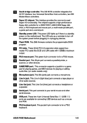
... for 3D sound ~ Two USB ports plus headers for four more 1.2 Package contents Check your ASUS P4SE package for the following items. ASUS P4SE motherboard ATX form factor: 12 in x 8.6 in the long line of ASUS quality motherboards! Thank you for a 3.5-inch floppy drive Bag of PC 2700 / 2100 / ...: PC2700 max. to 3GB of system memory of extra jumper caps User Guide 1-2 1.1 Welcome! The ASUS P4SE motherboard delivers a host of new features and latest technology making it another standout in ASUS P4SE support CD 1 pc. 80-conductor ribbon cable for UltraDMA/66/100/133 IDE drives 1 pc. 40...
... for 3D sound ~ Two USB ports plus headers for four more 1.2 Package contents Check your ASUS P4SE package for the following items. ASUS P4SE motherboard ATX form factor: 12 in x 8.6 in the long line of ASUS quality motherboards! Thank you for a 3.5-inch floppy drive Bag of PC 2700 / 2100 / ...: PC2700 max. to 3GB of system memory of extra jumper caps User Guide 1-2 1.1 Welcome! The ASUS P4SE motherboard delivers a host of new features and latest technology making it another standout in ASUS P4SE support CD 1 pc. 80-conductor ribbon cable for UltraDMA/66/100/133 IDE drives 1 pc. 40...

P4SE User Manual
Page 13
1.3 Motherboard components 1 2 3 45 6 7 8 9 10 16 15 17 14 13 12 11 18 19 25 24 23 ASUS P4SE Motherboard 22 21 20 1-3
1.3 Motherboard components 1 2 3 45 6 7 8 9 10 16 15 17 14 13 12 11 18 19 25 24 23 ASUS P4SE Motherboard 22 21 20 1-3
P4SE User Manual
Page 15
... (light blue) jack connects a tape player or other devices. 19 GAME/MIDI port. This Line Out (lime) jack connects a headphone or a speaker. 23 Serial port. ASUS P4SE Motherboard 1-5 These 32-bit PCI 2.2 expansion slots support bus master PCI cards like SCSI and LAN cards with 133MB/s maximum output. 17 PS/2 mouse port...
... (light blue) jack connects a tape player or other devices. 19 GAME/MIDI port. This Line Out (lime) jack connects a headphone or a speaker. 23 Serial port. ASUS P4SE Motherboard 1-5 These 32-bit PCI 2.2 expansion slots support bus master PCI cards like SCSI and LAN cards with 133MB/s maximum output. 17 PS/2 mouse port...

P4SE User Manual
Page 17
.... When lit, the onboard LED (LED1) indicates that the system is ON, in sleep mode, or in any motherboard component P4SE ® P4SE Onboard LED LED1 ON Standby Power OFF Powered Off ASUS P4SE Motherboard 1-7 Use a grounded wrist strap or touch a safely grounded object or to the motherboard, peripherals, and/or components. Failure to...
.... When lit, the onboard LED (LED1) indicates that the system is ON, in sleep mode, or in any motherboard component P4SE ® P4SE Onboard LED LED1 ON Standby Power OFF Powered Off ASUS P4SE Motherboard 1-7 Use a grounded wrist strap or touch a safely grounded object or to the motherboard, peripherals, and/or components. Failure to...

P4SE User Manual
Page 19
PCI slot 3 - - PCI slot 4 - - - shared AGP shared - - - ASUS P4SE Motherboard 1-9 Install the software drivers for the expansion card. 1.8.2 Standard Interrupt Assignments IRQ Priority Standard Function 0 1 System Timer 1 2 Keyboard Controller 2 N/A Programmable Interrupt Controller 3* 11 Communications ..." or that they support. 1.8.1 Configuring an expansion card After physically installing the expansion card, configure the card by adjusting the software settings. 1. 1.8 Expansion slots The P4SE motherboard has six (6) expansion slots. PCI slot 6 -
PCI slot 3 - - PCI slot 4 - - - shared AGP shared - - - ASUS P4SE Motherboard 1-9 Install the software drivers for the expansion card. 1.8.2 Standard Interrupt Assignments IRQ Priority Standard Function 0 1 System Timer 1 2 Keyboard Controller 2 N/A Programmable Interrupt Controller 3* 11 Communications ..." or that they support. 1.8.1 Configuring an expansion card After physically installing the expansion card, configure the card by adjusting the software settings. 1. 1.8 Expansion slots The P4SE motherboard has six (6) expansion slots. PCI slot 6 -

P4SE User Manual
Page 21
... 100MHz DRAM 100MHz 133MHz 150MHz 160MHz 166MHz ON 12345 ON 12345 ON 12345 ON 12345 ON 12345 ON 12345 P4SE ® CPU 105MHz DRAM 140MHz P4SE CPU External Frequency Selection 108MHz 144MHz 112MHz 149MHz 133MHz 133MHz 133MHz 166MHz 100MHz 200MHz Set the CPU frequency only ... send the CPU. Frequencies other than the recommended CPU bus frequencies are not guaranteed to wake up feature. P4SE ® KBPWR1 2 1 +5V 3 2 +5VSB (Default) P4SE Keyboard Power Setting ASUS P4SE Motherboard 1-11 This permits selection of the CPU's external frequency (or Bus Clock). To select the CPU ...
... 100MHz DRAM 100MHz 133MHz 150MHz 160MHz 166MHz ON 12345 ON 12345 ON 12345 ON 12345 ON 12345 ON 12345 P4SE ® CPU 105MHz DRAM 140MHz P4SE CPU External Frequency Selection 108MHz 144MHz 112MHz 149MHz 133MHz 133MHz 133MHz 166MHz 100MHz 200MHz Set the CPU frequency only ... send the CPU. Frequencies other than the recommended CPU bus frequencies are not guaranteed to wake up feature. P4SE ® KBPWR1 2 1 +5V 3 2 +5VSB (Default) P4SE Keyboard Power Setting ASUS P4SE Motherboard 1-11 This permits selection of the CPU's external frequency (or Bus Clock). To select the CPU ...
P4SE User Manual
Page 23
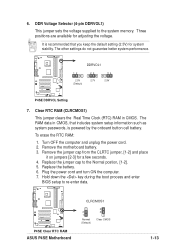
... the power cord and turn ON the computer. 7. P4SE ® P4SE Clear RTC RAM ASUS P4SE Motherboard CLRCMOS1 2 1 Normal (Default) 3 2 Clear CMOS 1-13 DDR Voltage Selector (4-pin DDRVOL1) This jumper sets the voltage supplied to the Normal postion, [1-2]. 5. It is powered by the onboard button cell battery. P4SE ® DDRVOL1 12 23 2.5V 2.7V (Default...
... the power cord and turn ON the computer. 7. P4SE ® P4SE Clear RTC RAM ASUS P4SE Motherboard CLRCMOS1 2 1 Normal (Default) 3 2 Clear CMOS 1-13 DDR Voltage Selector (4-pin DDRVOL1) This jumper sets the voltage supplied to the Normal postion, [1-2]. 5. It is powered by the onboard button cell battery. P4SE ® DDRVOL1 12 23 2.5V 2.7V (Default...

P4SE User Manual
Page 25
After connecting one end to the motherboard, connect the other end to the floppy drive. (Pin 5 is removed to PIN 1. 2. P4SE ® TIP: If the case-mounted LED does not light, try reversing the 2-pin plug. Floppy disk drive connector (34-1 pin FLOPPY)... red markings on the floppy ribbon cable to prevent incorrect insertion when using ribbon cables with pin 5 plug). IDELED1 P4SE IDE Activity LED 3. P4SE ® PIN 1 P4SE Floppy Disk Drive Connector ASUS P4SE Motherboard 1-15 Hard disk activity LED (2-pin IDELED1) This connector supplies power to light up. The read and write...
After connecting one end to the motherboard, connect the other end to the floppy drive. (Pin 5 is removed to PIN 1. 2. P4SE ® TIP: If the case-mounted LED does not light, try reversing the 2-pin plug. Floppy disk drive connector (34-1 pin FLOPPY)... red markings on the floppy ribbon cable to prevent incorrect insertion when using ribbon cables with pin 5 plug). IDELED1 P4SE IDE Activity LED 3. P4SE ® PIN 1 P4SE Floppy Disk Drive Connector ASUS P4SE Motherboard 1-15 Hard disk activity LED (2-pin IDELED1) This connector supplies power to light up. The read and write...

P4SE User Manual
Page 27
...Orient the fans so that allows multiple chips to connect to the same bus and enable each one to the fan connectors. P4SE ® P4SE SMBus Connector ASUS P4SE Motherboard SMB 1 FLOATING SMBCLK Ground SMBDATA +3V 1-17 Connect the fan cable to the connector matching the black wire to ...the ground pin. Lack of 1A (12W) at +12V. These are not jumpers! PWRFAN1 GND +12V Rotation P4SE ® P4SE 12-Volt Fan Connectors CPUFAN1...
...Orient the fans so that allows multiple chips to connect to the same bus and enable each one to the fan connectors. P4SE ® P4SE SMBus Connector ASUS P4SE Motherboard SMB 1 FLOATING SMBCLK Ground SMBDATA +3V 1-17 Connect the fan cable to the connector matching the black wire to ...the ground pin. Lack of 1A (12W) at +12V. These are not jumpers! PWRFAN1 GND +12V Rotation P4SE ® P4SE 12-Volt Fan Connectors CPUFAN1...

P4SE User Manual
Page 29
..., this motherboard requires that you are designed to fit these connectors in only one of the 4-pin device power plugs into the ASUS EZ Plug™ connector labeled AUX12V. The system may become unstable and may experience difficulty powering up if the power supply is 230W...12V GND GND +5V AUX12V1 +12.0VDC +5VSB PWR_OK COM +5.0VDC COM +5.0VDC COM +3.3VDC +3.3VDC P4SE ® +12V DC ATX12V1 P4SE ATX & Auxiliary Power Connectors +12V DC COM Pin 1 COM ASUS P4SE Motherboard 1-19 10. Find the proper orientation and push down firmly until the connectors completely fit. If you...
..., this motherboard requires that you are designed to fit these connectors in only one of the 4-pin device power plugs into the ASUS EZ Plug™ connector labeled AUX12V. The system may become unstable and may experience difficulty powering up if the power supply is 230W...12V GND GND +5V AUX12V1 +12.0VDC +5VSB PWR_OK COM +5.0VDC COM +5.0VDC COM +3.3VDC +3.3VDC P4SE ® +12V DC ATX12V1 P4SE ATX & Auxiliary Power Connectors +12V DC COM Pin 1 COM ASUS P4SE Motherboard 1-19 10. Find the proper orientation and push down firmly until the connectors completely fit. If you...

P4SE User Manual
Page 31
SPDIF_OUT1 P4SE ® P4SE Digital Audio Connector 14. ALOUT1 1 P4SE ® P4SE ALOUT Connector ALOUT1_LOUT_R BLOUT1_LOUT_L ALOUT1_LOUT_R BLOUT1_LOUT_L ASUS P4SE Motherboard 1-21 +5V SPDIFOUT GND 13. The S/PDIF Out module is not included in the motherboard package. Line out connector (5-pin ALOUT1) (on the motherboard, ...
SPDIF_OUT1 P4SE ® P4SE Digital Audio Connector 14. ALOUT1 1 P4SE ® P4SE ALOUT Connector ALOUT1_LOUT_R BLOUT1_LOUT_L ALOUT1_LOUT_R BLOUT1_LOUT_L ASUS P4SE Motherboard 1-21 +5V SPDIFOUT GND 13. The S/PDIF Out module is not included in the motherboard package. Line out connector (5-pin ALOUT1) (on the motherboard, ...

P4SE User Manual
Page 33
... system power. Pressing the power switch turns the system between ON and SLEEP, or ON and SOFT OFF, depending on the BIOS or OS settings. ASUS P4SE Motherboard 1-23
... system power. Pressing the power switch turns the system between ON and SLEEP, or ON and SOFT OFF, depending on the BIOS or OS settings. ASUS P4SE Motherboard 1-23

P4SE User Manual
Page 35
BIOS Information ASUS P4SE Motherboard 2-1 Chapter 2 This chapter gives information about the ASUS P4SE Binary Input/Output System (BIOS).This chapter includes updating the BIOS using the ASUS AFLASH BIOS that is bundled with the support CD.
BIOS Information ASUS P4SE Motherboard 2-1 Chapter 2 This chapter gives information about the ASUS P4SE Binary Input/Output System (BIOS).This chapter includes updating the BIOS using the ASUS AFLASH BIOS that is bundled with the support CD.

P4SE User Manual
Page 37
... type AFLASH and then press . 4. Type the filename of your problems. Careless updating may result to File from the Main menu and press . Select 1. ASUS P4SE Motherboard 2-3 Type a filename and the path, for example, A:\XXX-XX.XXX, then press . The Save Current BIOS To File screen appears. 6. At the...created earlier. 2. The Update BIOS Including Boot Block and ESCD screen appears. 5. Download an updated ASUS BIOS file from the floppy disk. 3. Boot from the Internet (WWW or FTP) (see ASUS CONTACT INFORMATION on page x for details) and save to the boot floppy disk you are sure ...
... type AFLASH and then press . 4. Type the filename of your problems. Careless updating may result to File from the Main menu and press . Select 1. ASUS P4SE Motherboard 2-3 Type a filename and the path, for example, A:\XXX-XX.XXX, then press . The Save Current BIOS To File screen appears. 6. At the...created earlier. 2. The Update BIOS Including Boot Block and ESCD screen appears. 5. Download an updated ASUS BIOS file from the floppy disk. 3. Boot from the Internet (WWW or FTP) (see ASUS CONTACT INFORMATION on page x for details) and save to the boot floppy disk you are sure ...

P4SE User Manual
Page 39
... menu or to locate and load the Operating System. EXIT Use this menu to configure the default system device used to exit the Setup program. ASUS P4SE Motherboard 2-5
... menu or to locate and load the Operating System. EXIT Use this menu to configure the default system device used to exit the Setup program. ASUS P4SE Motherboard 2-5

P4SE User Manual
Page 41
...: (00 to 23), Minute: (00 to 59), Second: (00 to 59). The sub-menu appears. While moving around through the various menus and sub-menus. ASUS P4SE Motherboard 2-7 Sub-menu Note that a right pointer symbol (as you specify (usually the current time). Use the legend keys to enter values and move between...
...: (00 to 23), Minute: (00 to 59), Second: (00 to 59). The sub-menu appears. While moving around through the various menus and sub-menus. ASUS P4SE Motherboard 2-7 Sub-menu Note that a right pointer symbol (as you specify (usually the current time). Use the legend keys to enter values and move between...

P4SE User Manual
Page 43
... Type HDD] Manually enter the number of cylinders, heads and sectors per track for the drive. Refer to automatically detect an IDE hard disk drive. ASUS P4SE Motherboard 2-9 Refer to halt. If automatic detection is successful, Setup automatically fills in the correct values for the remaining fields on this information. Halt On...
... Type HDD] Manually enter the number of cylinders, heads and sectors per track for the drive. Refer to automatically detect an IDE hard disk drive. ASUS P4SE Motherboard 2-9 Refer to halt. If automatic detection is successful, Setup automatically fills in the correct values for the remaining fields on this information. Halt On...

P4SE User Manual
Page 45
... field, set it manually. To make changes to this field, set a PIO (Programmed Input/Output) mode for compatible IDE devices. Configuration options: [0] [1] [2] [3] [4] [5] [Disabled] 2.3.2 Keyboard Features ASUS P4SE Motherboard 2-11 Configuration options: [Disabled] [Enabled] PIO Mode [4] This option lets you set the Type field to [User Type HDD]. Configuration options: [0] [1] [2] [3] [4] Ultra DMA Mode...
... field, set it manually. To make changes to this field, set a PIO (Programmed Input/Output) mode for compatible IDE devices. Configuration options: [0] [1] [2] [3] [4] [5] [Disabled] 2.3.2 Keyboard Features ASUS P4SE Motherboard 2-11 Configuration options: [Disabled] [Enabled] PIO Mode [4] This option lets you set the Type field to [User Type HDD]. Configuration options: [0] [1] [2] [3] [4] Ultra DMA Mode...

P4SE User Manual
Page 47
... select the core voltage supplied to the CPU(see next item). If not detected, the USB controller legacy mode is enabled. Configuration options: [Disabled] [Enabled] ASUS P4SE Motherboard 2-13 CPU VCore Setting [Auto] The [Manual] setting allows you to select a specific CPU core voltage. If detected, the USB controller legacy mode is...
... select the core voltage supplied to the CPU(see next item). If not detected, the USB controller legacy mode is enabled. Configuration options: [Disabled] [Enabled] ASUS P4SE Motherboard 2-13 CPU VCore Setting [Auto] The [Manual] setting allows you to select a specific CPU core voltage. If detected, the USB controller legacy mode is...


