
Motherboard DIY Troubleshooting Guide
Page 3
Features Contents Notices v Safety information vi About this guide vii P4S800D-E Deluxe specifications summary ix Chapter 1: Product introduction 1.1 Welcome 1-1 1.2 Package contents 1-1 1.3 Special features 1-2 1.3.1 Product Highlights 1-2 1.3.2 Unique ASUS features 1-4 Chapter 2: Hardware information 2.1 Before you proceed 1-1 2.2 Motherboard overview 1-2 2.2.1 Placement direction 1-2 2.2.2 Screw holes 1-2 2.2.3 Motherboard layout 1-3 2.2.4 Layout Contents 1-4 2.3 Central Processing Unit (CPU 1-6 2.3.1 Overview 1-6 2.3.2 Installing the CPU 1-7 2.3.3 Installing the heatsink...
Features Contents Notices v Safety information vi About this guide vii P4S800D-E Deluxe specifications summary ix Chapter 1: Product introduction 1.1 Welcome 1-1 1.2 Package contents 1-1 1.3 Special features 1-2 1.3.1 Product Highlights 1-2 1.3.2 Unique ASUS features 1-4 Chapter 2: Hardware information 2.1 Before you proceed 1-1 2.2 Motherboard overview 1-2 2.2.1 Placement direction 1-2 2.2.2 Screw holes 1-2 2.2.3 Motherboard layout 1-3 2.2.4 Layout Contents 1-4 2.3 Central Processing Unit (CPU 1-6 2.3.1 Overview 1-6 2.3.2 Installing the CPU 1-7 2.3.3 Installing the heatsink...

Motherboard DIY Troubleshooting Guide
Page 8
..., disconnect all power cables from the existing system before using an adpater or extension cord. viii Operation safety • Before installing the motherboard and adding devices on a stable surface. • If you are connected. Do not place the product in your area. Contact a...in any damage, contact your dealer immediately. • To avoid short circuits, keep paper clips, screws, and staples away from the motherboard, ensure that all cables are correctly connected and the power cables are unplugged. • Seek professional assistance before you detect any area ...
..., disconnect all power cables from the existing system before using an adpater or extension cord. viii Operation safety • Before installing the motherboard and adding devices on a stable surface. • If you are connected. Do not place the product in your area. Contact a...in any damage, contact your dealer immediately. • To avoid short circuits, keep paper clips, screws, and staples away from the motherboard, ensure that all cables are correctly connected and the power cables are unplugged. • Seek professional assistance before you detect any area ...

Motherboard DIY Troubleshooting Guide
Page 9
...8226; Chapter 4: BIOS setup This chapter tells how to perform when installing system components. It includes description of the jumpers and connectors on the motherboard. • Chapter 3: Powering up This chapter describes the power up sequence, the vocal POST messages, and ways of the and the new ...technologies it supports. • Chapter 2: Hardware information This chapter lists the hardware setup procedures that comes with the motherboard package. How this guide This user guide contains the information you have to change system settings through the BIOS Setup menus.
...8226; Chapter 4: BIOS setup This chapter tells how to perform when installing system components. It includes description of the jumpers and connectors on the motherboard. • Chapter 3: Powering up This chapter describes the power up sequence, the vocal POST messages, and ways of the and the new ...technologies it supports. • Chapter 2: Hardware information This chapter lists the hardware setup procedures that comes with the motherboard package. How this guide This user guide contains the information you have to change system settings through the BIOS Setup menus.

Motherboard DIY Troubleshooting Guide
Page 13
Product introduction Chapter 1 This chapter describes the motherboard features and the new technologies it supports.
Product introduction Chapter 1 This chapter describes the motherboard features and the new technologies it supports.

Motherboard DIY Troubleshooting Guide
Page 15
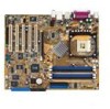
Supporting up to set a new benchmark for an effective desktop platform solution. ASUS P4S800D-E Deluxe motherboard 1-1 The motherboard delivers a host of new features and latest technologies making it , check the items in the world of ... the Intel® Pentium® 4 processor in the long line of system memory with the list below. 1.2 Package contents Check your motherboard package for the following items. ASUS P4S800D-E Deluxe motherboard ASUS motherboard support CD 2 x SATA cable 1 x SATA power cable 1 x 2-port USB+GAME module w/ cable 1 x 1394 module 1 x 80-conductor ribbon cable...
Supporting up to set a new benchmark for an effective desktop platform solution. ASUS P4S800D-E Deluxe motherboard 1-1 The motherboard delivers a host of new features and latest technologies making it , check the items in the world of ... the Intel® Pentium® 4 processor in the long line of system memory with the list below. 1.2 Package contents Check your motherboard package for the following items. ASUS P4S800D-E Deluxe motherboard ASUS motherboard support CD 2 x SATA cable 1 x SATA power cable 1 x 2-port USB+GAME module w/ cable 1 x 1394 module 1 x 80-conductor ribbon cable...
Motherboard DIY Troubleshooting Guide
Page 16
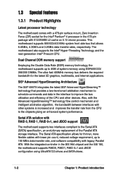
... next-generation Intel® Prescott CPU. Dual Channel DDR memory support Employing the Double Data Rate (DDR) memory technology, the motherboard supports up to 4GB of the Parallel ATA storage interface. With the integrated controller in the 478-pin package with 512/256KB L2...memory bus delivers the required bandwidth for the Intel® Pentium® 4 processor in the SIS 964 chipset and the SiS 180, the motherboard supports RAID0, RAID1, RAID 0+1 and JBOD configuration using UltraATA133 drives and SATA drives. 1-2 Chapter 1: Product introduction Also, with the Advanced ...
... next-generation Intel® Prescott CPU. Dual Channel DDR memory support Employing the Double Data Rate (DDR) memory technology, the motherboard supports up to 4GB of the Parallel ATA storage interface. With the integrated controller in the 478-pin package with 512/256KB L2...memory bus delivers the required bandwidth for the Intel® Pentium® 4 processor in the SIS 964 chipset and the SiS 180, the motherboard supports RAID0, RAID1, RAID 0+1 and JBOD configuration using UltraATA133 drives and SATA drives. 1-2 Chapter 1: Product introduction Also, with the Advanced ...

Motherboard DIY Troubleshooting Guide
Page 17
... of USB 2.0 allows connection of peripherals and devices compliant to IEEE 1394a standards. supporting up to 2.12 GB/s. ASUS P4S800D-E Deluxe motherboard 1-3 AGP 8X support AGP 8X (AGP 3.0) is the next generation VGA interface specification that enables enhanced graphics performance with... devices such as high resolution video conferencing cameras, next generation scanners and printers, and fast storage units. S/PDIF out The motherboard supports S/PDIF out function turns your computer into a high-end entertainment system with USB 1.1. 6-channel digital audio The ADI AD1888...
... of USB 2.0 allows connection of peripherals and devices compliant to IEEE 1394a standards. supporting up to 2.12 GB/s. ASUS P4S800D-E Deluxe motherboard 1-3 AGP 8X support AGP 8X (AGP 3.0) is the next generation VGA interface specification that enables enhanced graphics performance with... devices such as high resolution video conferencing cameras, next generation scanners and printers, and fast storage units. S/PDIF out The motherboard supports S/PDIF out function turns your computer into a high-end entertainment system with USB 1.1. 6-channel digital audio The ADI AD1888...

Motherboard DIY Troubleshooting Guide
Page 18
... alerts during the PowerOn Self-Tests (POST). See page 2-18. Se page 5-24. See page 4-30. ASUS POST Reporter The motherboard offers a new exciting feature called the ASUS POST Reporter to save the extra cost of three ASUS intelligent solutions: Q-Fan, POST Reporter, and CrashFree BIOS2. In addition, the card comes with the net...
... alerts during the PowerOn Self-Tests (POST). See page 2-18. Se page 5-24. See page 4-30. ASUS POST Reporter The motherboard offers a new exciting feature called the ASUS POST Reporter to save the extra cost of three ASUS intelligent solutions: Q-Fan, POST Reporter, and CrashFree BIOS2. In addition, the card comes with the net...

Motherboard DIY Troubleshooting Guide
Page 19
...a floppy disk. Instant Music This unique feature allows you can easily update the system BIOS even before loading the operating system. ASUS P4S800D-E Deluxe motherboard 1-5 ASUS EZ Flash BIOS With the ASUS EZ Flash, you to playback audio files even without booting the system to Windows™. See page 4-12. See pages ...information on the supported languages. CrashFree BIOS 2 This feature allows you to restore the original BIOS data from the ASUS support CD in the motherboard allows you to personalize and add style to your choice from the available options. Just press the...
...a floppy disk. Instant Music This unique feature allows you can easily update the system BIOS even before loading the operating system. ASUS P4S800D-E Deluxe motherboard 1-5 ASUS EZ Flash BIOS With the ASUS EZ Flash, you to playback audio files even without booting the system to Windows™. See page 4-12. See pages ...information on the supported languages. CrashFree BIOS 2 This feature allows you to restore the original BIOS data from the ASUS support CD in the motherboard allows you to personalize and add style to your choice from the available options. Just press the...

Motherboard DIY Troubleshooting Guide
Page 21
It includes description of the jumpers and connectors on the motherboard. Chapter 2 This chapter lists the hardware setup procedures that you have to perform when installing system components. Hardware information
It includes description of the jumpers and connectors on the motherboard. Chapter 2 This chapter lists the hardware setup procedures that you have to perform when installing system components. Hardware information

Motherboard DIY Troubleshooting Guide
Page 22
Chapter summary 2.1 Before you proceed 2-1 2.2 Motherboard overview 2-2 2.3 Central Processing Unit (CPU 2-6 2.4 System memory 2-12 2.5 Expansion slots 2-15 2.6 Jumpers 2-19 2.7 Connectors 2-21 ASUS P4S800D-E Deluxe motherboard
Chapter summary 2.1 Before you proceed 2-1 2.2 Motherboard overview 2-2 2.3 Central Processing Unit (CPU 2-6 2.4 System memory 2-12 2.5 Expansion slots 2-15 2.6 Jumpers 2-19 2.7 Connectors 2-21 ASUS P4S800D-E Deluxe motherboard

Motherboard DIY Troubleshooting Guide
Page 23
..., before handling components to avoid touching the ICs on a grounded antistatic pad or in any component. 2. Onboard LED The motherboard comes with the component. 5. Whenever you install or remove any component, ensure that the ATX power supply is detached from ...any component, place it on them due to the motherboard, peripherals, and/or components. 2.1 Before you proceed Take note of the onboard LED. ® P4S800D-E P4S800D-E Onboard LED SB_PWR1 ON Standby Power OFF Powered Off ASUS P4S800D-E Deluxe motherboard 2-1 The illustration below shows the location of the...
..., before handling components to avoid touching the ICs on a grounded antistatic pad or in any component. 2. Onboard LED The motherboard comes with the component. 5. Whenever you install or remove any component, ensure that the ATX power supply is detached from ...any component, place it on them due to the motherboard, peripherals, and/or components. 2.1 Before you proceed Take note of the onboard LED. ® P4S800D-E P4S800D-E Onboard LED SB_PWR1 ON Standby Power OFF Powered Off ASUS P4S800D-E Deluxe motherboard 2-1 The illustration below shows the location of the...

Motherboard DIY Troubleshooting Guide
Page 24
... the chassis in the image below. 2.2.2 Screw holes Place nine (9) screws into the holes indicated by circles to secure the motherboard to ensure that you install the motherboard, study the configuration of the chassis 2-2 Chapter 2: Hardware information Place this side towards the rear of your chassis to the ...chassis. Make sure to do so may damage the motherboard. Failure to unplug the power cord before installing or removing the motherboard. The edge with external ports goes to the rear part of the chassis as indicated in the ...
... the chassis in the image below. 2.2.2 Screw holes Place nine (9) screws into the holes indicated by circles to secure the motherboard to ensure that you install the motherboard, study the configuration of the chassis 2-2 Chapter 2: Hardware information Place this side towards the rear of your chassis to the ...chassis. Make sure to do so may damage the motherboard. Failure to unplug the power cord before installing or removing the motherboard. The edge with external ports goes to the rear part of the chassis as indicated in the ...

Motherboard DIY Troubleshooting Guide
Page 25
30.5cm (12.0in) 2.2.3 Motherboard layout 24.5cm (9.6in) PS/2KBMS T: Mouse B: Keyboard Socket 478 PWR_FAN1 CPU_FAN1 SPDIF_O ATX Power Connector SEC_IDE1 PRI_IDE1 DDR DIMM_A1 (64 bit,184-pin module) ... CD1 AUX1 Audio Codec SPDIF_OUT FP_AUDIO Accelerated Graphics Port (AGP1) PCI1 PCI2 ® PCI3 P4S800D-E PCI4 USB56 USBPW56 USBPW78 USB78 VIA VT6307 SiS 180 SiS 964 CR2032 3V Lithium Cell CMOS Power SATA2 SATA1 CLRTC1 SATA4 PRI_RAID1 4Mbit Firmware Hub Super I/O PCI5 SB_PWR1 WIFI IE1394_2 SATA3 COM2 GAME1 CHASSIS1 CHA_FAN1 PANEL1 ASUS P4S800D-E Deluxe motherboard 2-3
30.5cm (12.0in) 2.2.3 Motherboard layout 24.5cm (9.6in) PS/2KBMS T: Mouse B: Keyboard Socket 478 PWR_FAN1 CPU_FAN1 SPDIF_O ATX Power Connector SEC_IDE1 PRI_IDE1 DDR DIMM_A1 (64 bit,184-pin module) ... CD1 AUX1 Audio Codec SPDIF_OUT FP_AUDIO Accelerated Graphics Port (AGP1) PCI1 PCI2 ® PCI3 P4S800D-E PCI4 USB56 USBPW56 USBPW78 USB78 VIA VT6307 SiS 180 SiS 964 CR2032 3V Lithium Cell CMOS Power SATA2 SATA1 CLRTC1 SATA4 PRI_RAID1 4Mbit Firmware Hub Super I/O PCI5 SB_PWR1 WIFI IE1394_2 SATA3 COM2 GAME1 CHASSIS1 CHA_FAN1 PANEL1 ASUS P4S800D-E Deluxe motherboard 2-3

Motherboard DIY Troubleshooting Guide
Page 27
... (4-pin CD1) p. 2-28 14. Digital audio connector (6-1 pin SPDIF_OUT1) p. 2-29 18. System Power LED Lead (Green 3-1 pin PLED) - Hard Disk Activity LED (Red 2-pin IDE_LED) ASUS P4S800D-E Deluxe motherboard 2-5 Chassis fan connector (3-pin CHA_FAN1) p. 2-25 9. AUX connector (4-pin AUX1) p. 2-28 15. RAID ATA connector (40-1 pin PRI_RAID1) p. 2-23 5. Secondary IDE connector (40-1 pin SEC_IDE1...
... (4-pin CD1) p. 2-28 14. Digital audio connector (6-1 pin SPDIF_OUT1) p. 2-29 18. System Power LED Lead (Green 3-1 pin PLED) - Hard Disk Activity LED (Red 2-pin IDE_LED) ASUS P4S800D-E Deluxe motherboard 2-5 Chassis fan connector (3-pin CHA_FAN1) p. 2-25 9. AUX connector (4-pin AUX1) p. 2-28 15. RAID ATA connector (40-1 pin PRI_RAID1) p. 2-23 5. Secondary IDE connector (40-1 pin SEC_IDE1...

Motherboard DIY Troubleshooting Guide
Page 28
...Force (ZIF) socket designed for the Intel® Pentium® 4 processor. Under Linux, use the Hyper-Threading Technology on this motherboard: 1. If you are using any other operating systems, disable the Hyper-Threading Techonology item in BIOS before installing a supported operating system... installation. Under the Boot Menu, make sure that supports Hyper-Threading Technology. 2.3 Central Processing Unit (CPU) 2.3.1 Overview The motherboard comes with HyperThreading Technology. 2. Take note of the marked corner (with Gold Mark gold triangle) on the socket to ensure system ...
...Force (ZIF) socket designed for the Intel® Pentium® 4 processor. Under Linux, use the Hyper-Threading Technology on this motherboard: 1. If you are using any other operating systems, disable the Hyper-Threading Techonology item in BIOS before installing a supported operating system... installation. Under the Boot Menu, make sure that supports Hyper-Threading Technology. 2.3 Central Processing Unit (CPU) 2.3.1 Overview The motherboard comes with HyperThreading Technology. 2. Take note of the marked corner (with Gold Mark gold triangle) on the socket to ensure system ...

Motherboard DIY Troubleshooting Guide
Page 29
ASUS P4S800D-E Deluxe motherboard 2-7 2.3.2 Installing the CPU Follow these steps to 90°-100° angle, otherwise the CPU does not fit in completely. Socket Lever 90 - 100 Make sure that the socket lever is lifted up to a 90°-100° angle. Locate the 478-pin ZIF socket on the motherboard. 2. Unlock the socket by pressing the lever sideways, then lift it up to install a CPU. 1.
ASUS P4S800D-E Deluxe motherboard 2-7 2.3.2 Installing the CPU Follow these steps to 90°-100° angle, otherwise the CPU does not fit in completely. Socket Lever 90 - 100 Make sure that the socket lever is lifted up to a 90°-100° angle. Locate the 478-pin ZIF socket on the motherboard. 2. Unlock the socket by pressing the lever sideways, then lift it up to install a CPU. 1.

Motherboard DIY Troubleshooting Guide
Page 31
... and fan The Intel® Pentium® 4 Processor requires a specially designed heatsink and fan assembly to install the CPU heatsink and fan. 1. ASUS P4S800D-E Deluxe motherboard 2-9 If the instructions in this section do not have to remove the retention module base when installing the CPU or installing other... motherboard components. The retention module base is already installed on top of the installed CPU, making sure that you buy a boxed Intel Pentium ...
... and fan The Intel® Pentium® 4 Processor requires a specially designed heatsink and fan assembly to install the CPU heatsink and fan. 1. ASUS P4S800D-E Deluxe motherboard 2-9 If the instructions in this section do not have to remove the retention module base when installing the CPU or installing other... motherboard components. The retention module base is already installed on top of the installed CPU, making sure that you buy a boxed Intel Pentium ...

Motherboard DIY Troubleshooting Guide
Page 33
ASUS P4S800D-E Deluxe motherboard 2-11 3. Hardware monitoring errors may occur if you fail to connect the CPU fan connector! When secure, the retention locks should point to opposite directions. 2.3.4 Connecting the CPU fan cable When the fan, heatsink, and the retention mechanism are in place, connect the CPU fan cable to the connector on the retention mechanism to secure the heatsink and fan to the module base. Push down the locks on the motherboard labeled CPU_FAN1. CPU Fan Connector (CPU_FAN1) Don't forget to plug this connector.
ASUS P4S800D-E Deluxe motherboard 2-11 3. Hardware monitoring errors may occur if you fail to connect the CPU fan connector! When secure, the retention locks should point to opposite directions. 2.3.4 Connecting the CPU fan cable When the fan, heatsink, and the retention mechanism are in place, connect the CPU fan cable to the connector on the retention mechanism to secure the heatsink and fan to the module base. Push down the locks on the motherboard labeled CPU_FAN1. CPU Fan Connector (CPU_FAN1) Don't forget to plug this connector.

Motherboard DIY Troubleshooting Guide
Page 34
... first. 2-12 Chapter 2: Hardware information See list of the sockets. DIMM_A1 DIMM_A2 DIMM_B1 DIMM_B2 80 Pins 104 Pins ® P4S800D-E P4S800D-E 184-Pin DDR DIMM Sockets 2.4.2 Memory configurations You may cause memory sizing error or system boot failure. When all four sockets...with the same CAS latency. For optimum compatibility, it is recommended to the Southbridge resource allocation. 5. 2.4 System memory 2.4.1 Overview The motherboard comes with four Double Data Rate (DDR) Dual Inline Memory Module (DIMM) sockets. In Dual-channel configurations, install only identical (the...
... first. 2-12 Chapter 2: Hardware information See list of the sockets. DIMM_A1 DIMM_A2 DIMM_B1 DIMM_B2 80 Pins 104 Pins ® P4S800D-E P4S800D-E 184-Pin DDR DIMM Sockets 2.4.2 Memory configurations You may cause memory sizing error or system boot failure. When all four sockets...with the same CAS latency. For optimum compatibility, it is recommended to the Southbridge resource allocation. 5. 2.4 System memory 2.4.1 Overview The motherboard comes with four Double Data Rate (DDR) Dual Inline Memory Module (DIMM) sockets. In Dual-channel configurations, install only identical (the...


