
Motherboard DIY Troubleshooting Guide
Page 1
P4PE-X/TE Motherboard
P4PE-X/TE Motherboard

P4PE-X/TE User Manual
Page 1
Motherboard P4PE-X/TE User Guide
Motherboard P4PE-X/TE User Guide
P4PE-X/TE User Manual
Page 3
... more information vii ASUS contact information viii P4PE-X/TE specifications summary ix Chapter 1: Product introduction 1-1 1.1 Welcome 1-2 1.2 Package contents 1-2 1.3 Special features 1-2 1.4 Motherboard components 1-4 1.5 Motherboard layout 1-7 1.6 Before you proceed 1-8 1.7.1 Placement direction 1-9 1.7.2 Screw holes 1-9 1.7 Motherboard installation 1-9 1.8 ... slots 1-14 1.10.1 Standard interrupt assignments 1-14 1.10.2 IRQ assignments for this motherboard 1-14 1.11 Jumpers 1-15 1.12 Connectors 1-16 Chapter 2: BIOS information 2-1 2.1 Managing and updating your BIOS 2-2 ...
... more information vii ASUS contact information viii P4PE-X/TE specifications summary ix Chapter 1: Product introduction 1-1 1.1 Welcome 1-2 1.2 Package contents 1-2 1.3 Special features 1-2 1.4 Motherboard components 1-4 1.5 Motherboard layout 1-7 1.6 Before you proceed 1-8 1.7.1 Placement direction 1-9 1.7.2 Screw holes 1-9 1.7 Motherboard installation 1-9 1.8 ... slots 1-14 1.10.1 Standard interrupt assignments 1-14 1.10.2 IRQ assignments for this motherboard 1-14 1.11 Jumpers 1-15 1.12 Connectors 1-16 Chapter 2: BIOS information 2-1 2.1 Managing and updating your BIOS 2-2 ...
P4PE-X/TE User Manual
Page 6
... damage, contact your dealer immediately. • To avoid short circuits, keep paper clips, screws, and staples away from the motherboard, ensure that all the manuals that your retailer. Contact a qualified service technician or your area. If possible, disconnect all power...unplugged. • Seek professional assistance before the signal cables are using an adpater or extension cord. Operation safety • Before installing the motherboard and adding devices on a stable surface. • If you add a device. • Before connecting or removing signal cables from connectors...
... damage, contact your dealer immediately. • To avoid short circuits, keep paper clips, screws, and staples away from the motherboard, ensure that all the manuals that your retailer. Contact a qualified service technician or your area. If possible, disconnect all power...unplugged. • Seek professional assistance before the signal cables are using an adpater or extension cord. Operation safety • Before installing the motherboard and adding devices on a stable surface. • If you add a device. • Before connecting or removing signal cables from connectors...

P4PE-X/TE User Manual
Page 11
It includes brief descriptions of the motherboard components, and illustrations of the P4PE-X/TE motherboard. Product introduction Chapter 1 This chapter describes the features of the layout, jumper settings, and connectors.
It includes brief descriptions of the motherboard components, and illustrations of the P4PE-X/TE motherboard. Product introduction Chapter 1 This chapter describes the features of the layout, jumper settings, and connectors.

P4PE-X/TE User Manual
Page 12
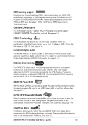
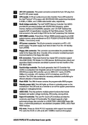
... Mbps LAN and 6-channel audio features, the P4PE-X/TE is damaged or missing, contact your affordable vehicle to set a new benchmark for buying the ASUS® P4PE-X/TE motherboard! Before you for a cost-effective desktop platform solution. The ASUS P4PE-X/TE motherboard delivers a host of new features and latest technologies... it , check the items in your package with the list below. *Overclocking mode 1.2 Package contents Check your P4PE-X/TE package for the following items. ASUS P4PE-X/TE motherboard ATX form factor: 12 in x 9 in the long line of the above items is your retailer. 1.3...
... Mbps LAN and 6-channel audio features, the P4PE-X/TE is damaged or missing, contact your affordable vehicle to set a new benchmark for buying the ASUS® P4PE-X/TE motherboard! Before you for a cost-effective desktop platform solution. The ASUS P4PE-X/TE motherboard delivers a host of new features and latest technologies... it , check the items in your package with the list below. *Overclocking mode 1.2 Package contents Check your P4PE-X/TE package for the following items. ASUS P4PE-X/TE motherboard ATX form factor: 12 in x 9 in the long line of the above items is your retailer. 1.3...
P4PE-X/TE User Manual
Page 13
... Recall) When the system hangs due to overclocking failure, there is no need to open the case to maximize your system performance. ASUS P4PE-X/TE motherboard user guide 1-3 ASUS EZ Flash BIOS With the ASUS EZ Flash, you to restore the original BIOS data from 12 Mbps on USB 1.1 to a fast 480 Mbps on the CPU...
... Recall) When the system hangs due to overclocking failure, there is no need to open the case to maximize your system performance. ASUS P4PE-X/TE motherboard user guide 1-3 ASUS EZ Flash BIOS With the ASUS EZ Flash, you to restore the original BIOS data from 12 Mbps on USB 1.1 to a fast 480 Mbps on the CPU...

P4PE-X/TE User Manual
Page 14
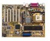
Refer to facilitate the installation and future upgrades. 1.4 Motherboard components Before you install the motherboard, learn about its major components and available features to the succeeding pages for the component descriptions. 1 23 4 5 6 7 16 15 8 14 13 17 26 25 1-4 12 11 10 9 18 19 20 21 22 24 23 Chapter 1: Product introduction
Refer to facilitate the installation and future upgrades. 1.4 Motherboard components Before you install the motherboard, learn about its major components and available features to the succeeding pages for the component descriptions. 1 23 4 5 6 7 16 15 8 14 13 17 26 25 1-4 12 11 10 9 18 19 20 21 22 24 23 Chapter 1: Product introduction
P4PE-X/TE User Manual
Page 15
...174; 845PE Memory Controller Hub (MCH) provides the processor interface with 533/400 MHz frequency, system memory interface at least 1A on the motherboard. The power supply must have at 333/266MHz operation, and 1.5V AGP interface that allows 6.4GB/s, 4.3GB/s, and 3.2GB/s data transfer... incorrect insertion of the floppy disk cable. 7 IDE connectors. This 2Mb firmware contains the programmable BIOS program. 10 Standby power LED. ASUS P4PE-X/TE motherboard user guide 1-5 This LED acts as a reminder to 2GB system memory using unbuffered non-ECC PC3200*/2700/2100/1600 DDR DIMMs. (*...
...174; 845PE Memory Controller Hub (MCH) provides the processor interface with 533/400 MHz frequency, system memory interface at least 1A on the motherboard. The power supply must have at 333/266MHz operation, and 1.5V AGP interface that allows 6.4GB/s, 4.3GB/s, and 3.2GB/s data transfer... incorrect insertion of the floppy disk cable. 7 IDE connectors. This 2Mb firmware contains the programmable BIOS program. 10 Standby power LED. ASUS P4PE-X/TE motherboard user guide 1-5 This LED acts as a reminder to 2GB system memory using unbuffered non-ECC PC3200*/2700/2100/1600 DDR DIMMs. (*...

P4PE-X/TE User Manual
Page 17
SEC_IDE PRI_IDE ATX Power Connector FLOPPY1 1.5 Motherboard layout PS/2KBMS T: Mouse B: Keyboard USB2.0 T: USB2 B: USB1 KBPWR1 USBPW12 COM1 22.86cm (9.0in) Socket 478 CPU_FAN1 CHA_FAN1 DDR DIMM1 (64/72 bit, 184-pin ... Graphics Port (AGP) RTL8100C PCI1 P4PE-X/TE PCI2 AD1888 SPDIF1 CD1 AUX1 PCI3 PCI4 PCI5 PCI6 01 23 45 Intel I/O Controller Hub (ICH4) ® CR2032 3V Lithium Cell CMOS Power CLRTC ASUS ASIC with Hardware Monitor SB_PWR1 CHASSIS1 2Mbit Firmware Hub Super I/O IDE_LED1 FP_AUDIO1 USB_56 GAME1 PANEL1 30.5cm (12.0in) ASUS P4PE-X/TE motherboard user guide 1-7
SEC_IDE PRI_IDE ATX Power Connector FLOPPY1 1.5 Motherboard layout PS/2KBMS T: Mouse B: Keyboard USB2.0 T: USB2 B: USB1 KBPWR1 USBPW12 COM1 22.86cm (9.0in) Socket 478 CPU_FAN1 CHA_FAN1 DDR DIMM1 (64/72 bit, 184-pin ... Graphics Port (AGP) RTL8100C PCI1 P4PE-X/TE PCI2 AD1888 SPDIF1 CD1 AUX1 PCI3 PCI4 PCI5 PCI6 01 23 45 Intel I/O Controller Hub (ICH4) ® CR2032 3V Lithium Cell CMOS Power CLRTC ASUS ASIC with Hardware Monitor SB_PWR1 CHASSIS1 2Mbit Firmware Hub Super I/O IDE_LED1 FP_AUDIO1 USB_56 GAME1 PANEL1 30.5cm (12.0in) ASUS P4PE-X/TE motherboard user guide 1-7
P4PE-X/TE User Manual
Page 18
... a grounded antistatic pad or in the bag that came with the component. 5. Before you install or remove any component, ensure that you uninstall any motherboard component. ® P4PE-X/TE P4PE-X/TE Onboard LED SB_PWR1 ON Standby Power OFF Powered Off 1-8 Chapter 1: Product introduction When lit, the standby LED (SB_PWR1) indicates that the system is switched...
... a grounded antistatic pad or in the bag that came with the component. 5. Before you install or remove any component, ensure that you uninstall any motherboard component. ® P4PE-X/TE P4PE-X/TE Onboard LED SB_PWR1 ON Standby Power OFF Powered Off 1-8 Chapter 1: Product introduction When lit, the standby LED (SB_PWR1) indicates that the system is switched...

P4PE-X/TE User Manual
Page 19
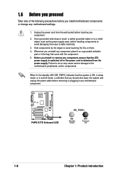
... goes to the rear part of the chassis ASUS P4PE-X/TE motherboard user guide 1-9 Doing so may cause you place it . Make sure to unplug the power cord before installing or removing the motherboard. 1.7 Motherboard installation Before you install the motherboard, study the configuration of your chassis to ensure... the chassis in the image below. 1.7.2 Screw holes Place seven (7) screws into the holes indicated by circles to secure the motherboard to the chassis. The motherboard uses the ATX form factor that measures 12 inches x 9 inches (30.5 cm x 22.9 cm). Place this side towards...
... goes to the rear part of the chassis ASUS P4PE-X/TE motherboard user guide 1-9 Doing so may cause you place it . Make sure to unplug the power cord before installing or removing the motherboard. 1.7 Motherboard installation Before you install the motherboard, study the configuration of your chassis to ensure... the chassis in the image below. 1.7.2 Screw holes Place seven (7) screws into the holes indicated by circles to secure the motherboard to the chassis. The motherboard uses the ATX form factor that measures 12 inches x 9 inches (30.5 cm x 22.9 cm). Place this side towards...
P4PE-X/TE User Manual
Page 20
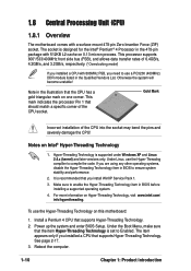
... the CPU! This mark indicates the processor Pin 1 that supports Hyper-Threading Technology. Under Linux, use the Hyper-Threading Technology on this motherboard: 1. 1.8 Central Processing Unit (CPU) 1.8.1 Overview The motherboard comes with 512KB L2 cache on 0.13 micron process. Hyper-Threading Technology is set to enable the Hyper-Threading Technology item in...
... the CPU! This mark indicates the processor Pin 1 that supports Hyper-Threading Technology. Under Linux, use the Hyper-Threading Technology on this motherboard: 1. 1.8 Central Processing Unit (CPU) 1.8.1 Overview The motherboard comes with 512KB L2 cache on 0.13 micron process. Hyper-Threading Technology is set to enable the Hyper-Threading Technology item in...

P4PE-X/TE User Manual
Page 21
... lever. 4. 1.8.2 Installing the CPU Follow these steps to indicate that it is locked. 6. When the CPU is lifted up to the CPU_FAN1 connector on the motherboard. 2. Position the CPU above the socket such that came with the heatsink package. 7. Connect the CPU fan cable to a 90°- 100° angle. DO... does not fit in one correct orientation. Gold Mark The CPU fits only in completely. 90 - 100 3. Locate the 478-pin ZIF socket on the motherboard. ASUS P4PE-X/TE motherboard user guide 1-11 The lever clicks on the side tab to install a CPU. 1.
... lever. 4. 1.8.2 Installing the CPU Follow these steps to indicate that it is locked. 6. When the CPU is lifted up to the CPU_FAN1 connector on the motherboard. 2. Position the CPU above the socket such that came with the heatsink package. 7. Connect the CPU fan cable to a 90°- 100° angle. DO... does not fit in one correct orientation. Gold Mark The CPU fits only in completely. 90 - 100 3. Locate the 478-pin ZIF socket on the motherboard. ASUS P4PE-X/TE motherboard user guide 1-11 The lever clicks on the side tab to install a CPU. 1.

P4PE-X/TE User Manual
Page 22
...sockets. (*Overclocking mode) If you must leave DIMM3 socket empty. 2. x16 Double-sided DDR DIMMs (16-bit memory chips) are not supported on this motherboard. 3. Without an 800MHz FSB CPU, the DDR module can only run at the same time but neither one can be x16 DDR module. 1-12 Chapter...and 3 share the same rows, so if you install a double-sided DIMM into DIMM2 and DIMM3 sockets at 333MHz or lower frequency. ® P4PE-X/TE 80 Pins 104 Pins P4PE-X/TE 184-Pin DDR DIMM Sockets 1.9.1 Memory configurations You may not boot up to 2GB system memory using 184-pin unbuffered non-ECC PC3200...
...sockets. (*Overclocking mode) If you must leave DIMM3 socket empty. 2. x16 Double-sided DDR DIMMs (16-bit memory chips) are not supported on this motherboard. 3. Without an 800MHz FSB CPU, the DDR module can only run at the same time but neither one can be x16 DDR module. 1-12 Chapter...and 3 share the same rows, so if you install a double-sided DIMM into DIMM2 and DIMM3 sockets at 333MHz or lower frequency. ® P4PE-X/TE 80 Pins 104 Pins P4PE-X/TE 184-Pin DDR DIMM Sockets 1.9.1 Memory configurations You may not boot up to 2GB system memory using 184-pin unbuffered non-ECC PC3200...

P4PE-X/TE User Manual
Page 23
... (www.asus.com) for the latest qualified vendors list (QVL). 1.9.2 Installing a DIMM Make sure to unplug the power supply before installing PC3200 DDR memory modules. Follow these steps to both the motherboard and the components. This motherboard supports different memory frequencies depending on the socket. 3. ...on the DIMM matches the break on the CPU FSB (Front Side Bus) and the type of DDR DIMM. Unlocked Retaining Clip ASUS P4PE-X/TE motherboard user guide 1-13 CPU FSB DDR DIMM Type Memory Frequency *800 MHz *PC3200 *400 MHz 533 MHz PC2700/PC2100 333/266 ...
... (www.asus.com) for the latest qualified vendors list (QVL). 1.9.2 Installing a DIMM Make sure to unplug the power supply before installing PC3200 DDR memory modules. Follow these steps to both the motherboard and the components. This motherboard supports different memory frequencies depending on the socket. 3. ...on the DIMM matches the break on the CPU FSB (Front Side Bus) and the type of DDR DIMM. Unlocked Retaining Clip ASUS P4PE-X/TE motherboard user guide 1-13 CPU FSB DDR DIMM Type Memory Frequency *800 MHz *PC3200 *400 MHz 533 MHz PC2700/PC2100 333/266 ...

P4PE-X/TE User Manual
Page 24
... on the system and change the necessary BIOS settings, if any. 1.10 Expansion slots The motherboard has six PCI slots and one Accelerated Graphics Port (AGP) slot. Turn on shared slots,...PCI slot 5 -- shared - - - - - - - - - - shared - - C D E F GH - - - shared - - - - - - - - - -- - - - - -- - NOTE: The AGP slot supports only 1.5V AGP cards. 2. See Chapter 2 for this motherboard AB PCI slot 1 -- PCI slot 4 -- PCI slot 6 -- shared - - Otherwise, conflicts arise between the two PCI groups making the system unstable and the card inoperable. 1-14...
... on the system and change the necessary BIOS settings, if any. 1.10 Expansion slots The motherboard has six PCI slots and one Accelerated Graphics Port (AGP) slot. Turn on shared slots,...PCI slot 5 -- shared - - - - - - - - - - shared - - C D E F GH - - - shared - - - - - - - - - -- - - - - -- - NOTE: The AGP slot supports only 1.5V AGP cards. 2. See Chapter 2 for this motherboard AB PCI slot 1 -- PCI slot 4 -- PCI slot 6 -- shared - - Otherwise, conflicts arise between the two PCI groups making the system unstable and the card inoperable. 1-14...

P4PE-X/TE User Manual
Page 25
...default values. Move the jumper cap from pins 1-2 (default) to overclocking. Removing the cap will cause system boot failure! ® P4PE-X/TE CLRTC 12 23 P4PE-X/TE Clear RTC RAM Normal (Default) Clear CMOS You do not need to clear the RTC when the system hangs due to pins 2-3. ...computer and unplug the power cord. 2. Keep the cap on CLRTC1 jumper default position. Plug the power cord and turn ON the computer. 4. ASUS P4PE-X/TE motherboard user guide 1-15 Clear RTC RAM (CLRTC1) This jumper allows clearing the Real Time Clock (RTC) RAM in the BIOS (see section 2.5.1 ...
...default values. Move the jumper cap from pins 1-2 (default) to overclocking. Removing the cap will cause system boot failure! ® P4PE-X/TE CLRTC 12 23 P4PE-X/TE Clear RTC RAM Normal (Default) Clear CMOS You do not need to clear the RTC when the system hangs due to pins 2-3. ...computer and unplug the power cord. 2. Keep the cap on CLRTC1 jumper default position. Plug the power cord and turn ON the computer. 4. ASUS P4PE-X/TE motherboard user guide 1-15 Clear RTC RAM (CLRTC1) This jumper allows clearing the Real Time Clock (RTC) RAM in the BIOS (see section 2.5.1 ...

P4PE-X/TE User Manual
Page 26
...5VSB to CPU, DRAM in slow refresh, power supply in reduced power mode). USBPW12 12 23 ® P4PE-X/TE +5V (Default) +5VSB USBPW34 USBPW56 12 23 +5V P4PE-X/TE USB Device Wake Up (Default) +5VSB 1.12 Connectors This section describes and illustrates the internal connectors on ...) This connector supplies power to +5VSB. 3. This feature requires a power supply that you can provide at least 1A on the motherboard. 1. IDE_LED1 P4PE-X/TE HD Activity LED 1-16 Chapter 1: Product introduction USB device wake-up from S1 sleep mode (CPU stopped, DRAM refreshed, system running...
...5VSB to CPU, DRAM in slow refresh, power supply in reduced power mode). USBPW12 12 23 ® P4PE-X/TE +5V (Default) +5VSB USBPW34 USBPW56 12 23 +5V P4PE-X/TE USB Device Wake Up (Default) +5VSB 1.12 Connectors This section describes and illustrates the internal connectors on ...) This connector supplies power to +5VSB. 3. This feature requires a power supply that you can provide at least 1A on the motherboard. 1. IDE_LED1 P4PE-X/TE HD Activity LED 1-16 Chapter 1: Product introduction USB device wake-up from S1 sleep mode (CPU stopped, DRAM refreshed, system running...
P4PE-X/TE User Manual
Page 27
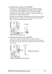
... 5 is for a chassis designed with a jumper cap. By default, the pins labeled "Chassis Signal" and "Ground" are shorted with intrusion detection feature. PIN 1 P4PE-X/TE Floppy Disk Drive Connector ASUS P4PE-X/TE motherboard user guide 1-17 This requires an external detection mechanism such as a chassis intrusion sensor or microswitch. +5VSB_MB Chassis Signal GND 2. If you remove...
... 5 is for a chassis designed with a jumper cap. By default, the pins labeled "Chassis Signal" and "Ground" are shorted with intrusion detection feature. PIN 1 P4PE-X/TE Floppy Disk Drive Connector ASUS P4PE-X/TE motherboard user guide 1-17 This requires an external detection mechanism such as a chassis intrusion sensor or microswitch. +5VSB_MB Chassis Signal GND 2. If you remove...


