Asus P4P800S SE
Related Manual Pages


Related Videos

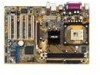
ASUS P4P800S SE
Duration: :52
Total Views: 147
Duration: :52
Total Views: 147
Similar Questions

I Need A Support Cd. Were Can I Download Latest Version?
(Posted by perjerker 9 years ago)

Graphics Is No Good
My ASUS P4S8X-MX works okay but, it can't play youtube and other video clips smoothly, and doesn't o...
My ASUS P4S8X-MX works okay but, it can't play youtube and other video clips smoothly, and doesn't o...
(Posted by kuslevbm 10 years ago)