
P4P800-X user's manual English version E1718
Page 12
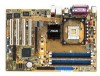
... frequencies for the latest 3D graphics, multimedia, and Internet applications. 1-2 Chapter 1: Product introduction The ASUS P4P800-X motherboard, based on it another standout in your package with the list below. 1.2 Package contents Check your P4P800-X package for the following items. ASUS P4P800-X motherboard ASUS motherboard support CD 2 x Serial ATA cable 1 x UltraDMA 100/66 cable 1 x Floppy disk cable...
... frequencies for the latest 3D graphics, multimedia, and Internet applications. 1-2 Chapter 1: Product introduction The ASUS P4P800-X motherboard, based on it another standout in your package with the list below. 1.2 Package contents Check your P4P800-X package for the following items. ASUS P4P800-X motherboard ASUS motherboard support CD 2 x Serial ATA cable 1 x UltraDMA 100/66 cable 1 x Floppy disk cable...

P4P800-X user's manual English version E1718
Page 13
...100 Mbps LAN support Easy connectivity to your network or broadband connection with high bandwidth speeds up to 30% (depending on USB 2.0. ASUS Hyper-Path Technology This unique technology from 12 Mbps on USB 1.1 to a fast 480 Mbps on the installed CPU and DRAM) ...MB/s data transfer rate, and software compatibility with legacy Parallel ATA. CrashFree BIOS 2 This feature allows you to buy a replacement ROM chip. ASUS P4P800-X motherboard 1-3 The Serial ATA specification allows for 5.1 surround sound using digital audio devices via a Sony/Philips Digital Interface (S/PDIF) jack located...
...100 Mbps LAN support Easy connectivity to your network or broadband connection with high bandwidth speeds up to 30% (depending on USB 2.0. ASUS Hyper-Path Technology This unique technology from 12 Mbps on USB 1.1 to a fast 480 Mbps on the installed CPU and DRAM) ...MB/s data transfer rate, and software compatibility with legacy Parallel ATA. CrashFree BIOS 2 This feature allows you to buy a replacement ROM chip. ASUS P4P800-X motherboard 1-3 The Serial ATA specification allows for 5.1 surround sound using digital audio devices via a Sony/Philips Digital Interface (S/PDIF) jack located...

P4P800-X user's manual English version E1718
Page 15
... Out Below:Mic In CD AUX FP_AUDIO SPDIF_OUT AD1888 RTL8101L Super I/O 3Mb FWH Intel 865PE MCH SEC_IDE Accelerated Graphics Port (AGP) CLRTC CHASSIS PCI1 PCI2 P4P800-X PCI3 ® PCI4 COM2 GAME Intel ICH5 FLOPPY CR2032 3V Lithium Cell CMOS Power SATA2 SATA1 SB_PWR CHA_FAN USBPW56 USBPW78 USB56 USB78 PANEL 30.5cm...
... Out Below:Mic In CD AUX FP_AUDIO SPDIF_OUT AD1888 RTL8101L Super I/O 3Mb FWH Intel 865PE MCH SEC_IDE Accelerated Graphics Port (AGP) CLRTC CHASSIS PCI1 PCI2 P4P800-X PCI3 ® PCI4 COM2 GAME Intel ICH5 FLOPPY CR2032 3V Lithium Cell CMOS Power SATA2 SATA1 SB_PWR CHA_FAN USBPW56 USBPW78 USB56 USB78 PANEL 30.5cm...

P4P800-X user's manual English version E1718
Page 17
...the item Hyper-Threading Technology is supported under Windows® XP/2003 Server and Linux 2.4.x (kernel) and later versions only. P4P800-X ® P4P800-X CPU Socket 478 Gold Arrow Incorrect installation of the CPU socket. If you installed a CPU that supports Hyper-Threading Technology....and enter BIOS Setup (see Chapter 2). Reboot the computer. Notes on Hyper-Threading Technology, visit www.intel.com/ info/hyperthreading. ASUS P4P800-X motherboard 1-7 Install the CPU. 2. Under the Advanced Menu, make sure that should match a specific corner of the CPU into ...
...the item Hyper-Threading Technology is supported under Windows® XP/2003 Server and Linux 2.4.x (kernel) and later versions only. P4P800-X ® P4P800-X CPU Socket 478 Gold Arrow Incorrect installation of the CPU socket. If you installed a CPU that supports Hyper-Threading Technology....and enter BIOS Setup (see Chapter 2). Reboot the computer. Notes on Hyper-Threading Technology, visit www.intel.com/ info/hyperthreading. ASUS P4P800-X motherboard 1-7 Install the CPU. 2. Under the Advanced Menu, make sure that should match a specific corner of the CPU into ...

P4P800-X user's manual English version E1718
Page 19
... or system boot failure. 1.7 System memory 1.7.1 DIMM sockets location The following figure illustrates the location of the DDR DIMM sockets. 80 Pins 104 Pins P4P800-X ® P4P800-X 184-Pin DDR DIMM sockets DIMM_A1 DIMM_A2 DIMM_B1 DIMM_B2 Make sure to unplug the power supply before adding or removing DIMMs or other than 4 GB... may detect only 3+ GB (a little less than the recommended configurations may run in a lower frequency. Use any three memory sockets will function in this section. ASUS P4P800-X motherboard 1-9
... or system boot failure. 1.7 System memory 1.7.1 DIMM sockets location The following figure illustrates the location of the DDR DIMM sockets. 80 Pins 104 Pins P4P800-X ® P4P800-X 184-Pin DDR DIMM sockets DIMM_A1 DIMM_A2 DIMM_B1 DIMM_B2 Make sure to unplug the power supply before adding or removing DIMMs or other than 4 GB... may detect only 3+ GB (a little less than the recommended configurations may run in a lower frequency. Use any three memory sockets will function in this section. ASUS P4P800-X motherboard 1-9
P4P800-X user's manual English version E1718
Page 21
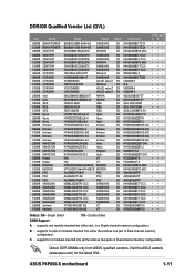
Double Sided DIMM Support: A - C - ASUS P4P800-X motherboard 1-11 supports on pair of modules inserted into either slot, in a Single-channel memory configuration. B - support for the latest QVL. Visit the ASUS website (www.asus.com) for 4 modules inserted into either the slots as one module inserted ...into all the slots as two pairs of Dual-channel memory configuration. Obtain DDR DIMMs only from ASUS qualified vendors. supports one pair of Dual-channel memory configuration. DDR400 Qualified Vendor List (QVL) Size Vendor 256MB BRAIN ...
Double Sided DIMM Support: A - C - ASUS P4P800-X motherboard 1-11 supports on pair of modules inserted into either slot, in a Single-channel memory configuration. B - support for the latest QVL. Visit the ASUS website (www.asus.com) for 4 modules inserted into either the slots as one module inserted ...into all the slots as two pairs of Dual-channel memory configuration. Obtain DDR DIMMs only from ASUS qualified vendors. supports one pair of Dual-channel memory configuration. DDR400 Qualified Vendor List (QVL) Size Vendor 256MB BRAIN ...

P4P800-X user's manual English version E1718
Page 23
... card: 1. Onboard LAN -- shared shared shared shared - - - Install an expansion card following the instructions that the cards do not need IRQ assignments. shared - - - - - -- - PCI slot 3 -- ASUS P4P800-X motherboard 1-13
... card: 1. Onboard LAN -- shared shared shared shared - - - Install an expansion card following the instructions that the cards do not need IRQ assignments. shared - - - - - -- - PCI slot 3 -- ASUS P4P800-X motherboard 1-13

P4P800-X user's manual English version E1718
Page 25
... erase the RTC RAM: 1. Move the jumper cap from pins 1-2 (default) to overclocking. Plug the power cord and turn ON the computer. 4. P4P800-X ® P4P800-X Clear RTC RAM CLRTC 2 1 Normal (Default) 3 2 Clear CMOS You do not need to clear the RTC when the system hangs due to ...Time Clock (RTC) RAM in CMOS, that include system setup information such as system passwords, is powered by erasing the CMOS RTC RAM data. ASUS P4P800-X motherboard 1-15 1.9 Jumpers 1. Keep the cap on CLRTC1 jumper default position. Turn OFF the computer and unplug the power cord. 2. The RAM...
... erase the RTC RAM: 1. Move the jumper cap from pins 1-2 (default) to overclocking. Plug the power cord and turn ON the computer. 4. P4P800-X ® P4P800-X Clear RTC RAM CLRTC 2 1 Normal (Default) 3 2 Clear CMOS You do not need to clear the RTC when the system hangs due to ...Time Clock (RTC) RAM in CMOS, that include system setup information such as system passwords, is powered by erasing the CMOS RTC RAM data. ASUS P4P800-X motherboard 1-15 1.9 Jumpers 1. Keep the cap on CLRTC1 jumper default position. Turn OFF the computer and unplug the power cord. 2. The RAM...
P4P800-X user's manual English version E1718
Page 27
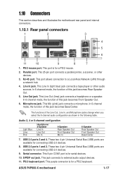
... you select the 6-channel audio configuration as shown in the following table. Microphone jack. This 9-pin COM1 port is for a PS/2 mouse. 2. S/PDIF out jack. ASUS P4P800-X motherboard 1-17 This 25-pin port connects a parallel printer, a scanner, or other audio sources. RJ-45 port. USB 2.0 ports 1 and 2. PS/2 keyboard port. This port...
... you select the 6-channel audio configuration as shown in the following table. Microphone jack. This 9-pin COM1 port is for a PS/2 mouse. 2. S/PDIF out jack. ASUS P4P800-X motherboard 1-17 This 25-pin port connects a parallel printer, a scanner, or other audio sources. RJ-45 port. USB 2.0 ports 1 and 2. PS/2 keyboard port. This port...
P4P800-X user's manual English version E1718
Page 29
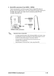
3. ASUS P4P800-X motherboard 1-19 Serial ATA connectors (7-pin SATA1, SATA2) These next generation connectors support the thin Serial ATA cables for Serial ATA drive and connections are ...). • Hot plug support for primary internal storage devices. SATA2 GND RSATA_RXP2 RSATA_RXN2 GND RSATA_TXN2 RSATA_TXP2 GND GND RSATA_RXP1 RSATA_RXN1 GND RSATA_TXN1 RSATA_TXP1 GND P4P800-X ® SATA1 P4P800-X SATA connectors Important notes on Serial ATA • In a legacy operating system (DOS, Windows 98/ME) environment, using the Serial ATA connectors will disable...
3. ASUS P4P800-X motherboard 1-19 Serial ATA connectors (7-pin SATA1, SATA2) These next generation connectors support the thin Serial ATA cables for Serial ATA drive and connections are ...). • Hot plug support for primary internal storage devices. SATA2 GND RSATA_RXP2 RSATA_RXN2 GND RSATA_TXN2 RSATA_TXP2 GND GND RSATA_RXP1 RSATA_RXN1 GND RSATA_TXN1 RSATA_TXP1 GND P4P800-X ® SATA1 P4P800-X SATA connectors Important notes on Serial ATA • In a legacy operating system (DOS, Windows 98/ME) environment, using the Serial ATA connectors will disable...
P4P800-X user's manual English version E1718
Page 31
... the power supply is 300W for a fully configured system. In addition to the CPU. ATX12V +12V DC GND +12V DC GND P4P800-X ® P4P800-X ATX power connectors ATXPWR Pin 1 +12.0VDC +5VSB PWR_OK COM +5.0VDC COM +5.0VDC COM +3.3VDC +3.3VDC +5.0VDC +5.0VDC -5....(+5VSB). 4. The minimum recommended wattage is inadequate. CD (Black) P4P800-X ® AUX (White) P4P800-X Internal audio connectors Right Audio Channel Ground Ground Left Audio Channel Right Audio Channel Ground Ground Left Audio Channel ASUS P4P800-X motherboard 1-21 Make sure that you to connect the 4-pin ATX12V...
... the power supply is 300W for a fully configured system. In addition to the CPU. ATX12V +12V DC GND +12V DC GND P4P800-X ® P4P800-X ATX power connectors ATXPWR Pin 1 +12.0VDC +5VSB PWR_OK COM +5.0VDC COM +5.0VDC COM +3.3VDC +3.3VDC +5.0VDC +5.0VDC -5....(+5VSB). 4. The minimum recommended wattage is inadequate. CD (Black) P4P800-X ® AUX (White) P4P800-X Internal audio connectors Right Audio Channel Ground Ground Left Audio Channel Right Audio Channel Ground Ground Left Audio Channel ASUS P4P800-X motherboard 1-21 Make sure that you to connect the 4-pin ATX12V...
P4P800-X user's manual English version E1718
Page 33
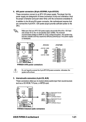
AGND +5VA BLINE_OUT_R BLINE_OUT_L MIC2 MICPWR Line out_R NC Line out_L FP_AUDIO P4P800-X ® P4P800-X Front panel audio connector 9. This requires an external detection mechanism such as a chassis intrusion sensor or microswitch. ... pin FP_AUDIO) This is for the front panel cable that allows convenient connection and control of audio devices. P4P800-X ® CHASSIS GND Chassis Signal (Default) +5VSB_MB P4P800-X Chassis intrusion connector ASUS P4P800-X motherboard 1-23 Chassis intrusion connector (4-1 pin CHASSIS) This lead is an interface for a chassis designed with...
AGND +5VA BLINE_OUT_R BLINE_OUT_L MIC2 MICPWR Line out_R NC Line out_L FP_AUDIO P4P800-X ® P4P800-X Front panel audio connector 9. This requires an external detection mechanism such as a chassis intrusion sensor or microswitch. ... pin FP_AUDIO) This is for the front panel cable that allows convenient connection and control of audio devices. P4P800-X ® CHASSIS GND Chassis Signal (Default) +5VSB_MB P4P800-X Chassis intrusion connector ASUS P4P800-X motherboard 1-23 Chassis intrusion connector (4-1 pin CHASSIS) This lead is an interface for a chassis designed with...

P4P800-X user's manual English version E1718
Page 35
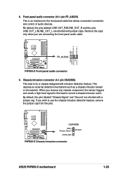
...pin PANEL) This connector accommodates several system front panel functions. ASUS P4P800-X motherboard 1-25 Serial connector (9-pin COM2 ) This 9-pin connector connects to hear system beeps and warnings. COM2 PIN 1 P4P800-X ® P4P800-X Serial port connector The COM2 bracket is in the rear ...to the system power LED. Speaker Power LED Connector +5 V PLED +5V Ground Ground Speaker PANEL HD_LED+ HD_LEDPWRBIN Ground Reset Ground P4P800-X R P4P800-X System panel connector IDELED Reset SW ATX Power Switch* * Requires an ATX power supply. • System Power LED Lead (Green...
...pin PANEL) This connector accommodates several system front panel functions. ASUS P4P800-X motherboard 1-25 Serial connector (9-pin COM2 ) This 9-pin connector connects to hear system beeps and warnings. COM2 PIN 1 P4P800-X ® P4P800-X Serial port connector The COM2 bracket is in the rear ...to the system power LED. Speaker Power LED Connector +5 V PLED +5V Ground Ground Speaker PANEL HD_LED+ HD_LEDPWRBIN Ground Reset Ground P4P800-X R P4P800-X System panel connector IDELED Reset SW ATX Power Switch* * Requires an ATX power supply. • System Power LED Lead (Green...
P4P800-X user's manual English version E1718
Page 39
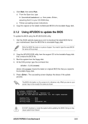
... the bootable floppy disk. 2.1.2 Using AFUDOS to a bootable floppy disk. Copy the AFUDOS.EXE utility from the floppy disk. 4. Press . ASUS P4P800-X motherboard 2-3 Follow succeeding screen instructions. 2. Visit the ASUS website (www.asus.com) to the bootable floppy disk. 5. You need to the bootable floppy disk that contains the BIOS file. 3. Write the BIOS...
... the bootable floppy disk. 2.1.2 Using AFUDOS to a bootable floppy disk. Copy the AFUDOS.EXE utility from the floppy disk. 4. Press . ASUS P4P800-X motherboard 2-3 Follow succeeding screen instructions. 2. Visit the ASUS website (www.asus.com) to the bootable floppy disk. 5. You need to the bootable floppy disk that contains the BIOS file. 3. Write the BIOS...

P4P800-X user's manual English version E1718
Page 41
... the latest BIOS file for floppy... • If there is displayed. Version 1.10 Copyright (C) 2002 American Megatrends, Inc. Visit the ASUS website (www.asus.com) to rename the downloaded BIOS file as P4P800X.ROM. Save the BIOS file to display the following. is no floppy disk in the... 3. Checking for your motherboard and rename the downloaded file as "P4P800X.ROM". 4. 3. appears. • If the correct BIOS file is not writeprotected. ASUS P4P800-X motherboard 2-5 Insert the floppy disk that the floppy disk has at least 600KB of booting from a diskette and using...
... the latest BIOS file for floppy... • If there is displayed. Version 1.10 Copyright (C) 2002 American Megatrends, Inc. Visit the ASUS website (www.asus.com) to rename the downloaded BIOS file as P4P800X.ROM. Save the BIOS file to display the following. is no floppy disk in the... 3. Checking for your motherboard and rename the downloaded file as "P4P800X.ROM". 4. 3. appears. • If the correct BIOS file is not writeprotected. ASUS P4P800-X motherboard 2-5 Insert the floppy disk that the floppy disk has at least 600KB of booting from a diskette and using...

P4P800-X user's manual English version E1718
Page 43
.... DO NOT shut down or reset the system while updating the BIOS! Starting BIOS recovery... When the BIOS update process is no floppy disk found ! ASUS P4P800-X motherboard 2-7 To recover the BIOS from the support CD: 1. Checking for floppy... If there is complete, reboot the system. Checking for CD-ROM... Start flashing...
.... DO NOT shut down or reset the system while updating the BIOS! Starting BIOS recovery... When the BIOS update process is no floppy disk found ! ASUS P4P800-X motherboard 2-7 To recover the BIOS from the support CD: 1. Checking for floppy... If there is complete, reboot the system. Checking for CD-ROM... Start flashing...

P4P800-X user's manual English version E1718
Page 45
Use [+] or [-] to another. Select Screen Select Item +- ASUS P4P800-X motherboard 2-9 Use the navigation keys to select items in ] Primary IDE Master Primary IDE Slave Secondary IDE Master Secondary IDE Slave Third IDE Master Fourth IDE Master IDE Configuration System Information :[ST320413A] :[ASUS CD-S340] :[Not Detected] :[Not Detected] :[Not Detected] :[Not Detected] Use...
Use [+] or [-] to another. Select Screen Select Item +- ASUS P4P800-X motherboard 2-9 Use the navigation keys to select items in ] Primary IDE Master Primary IDE Slave Secondary IDE Master Secondary IDE Slave Third IDE Master Fourth IDE Master IDE Configuration System Information :[ST320413A] :[ASUS CD-S340] :[Not Detected] :[Not Detected] :[Not Detected] :[Not Detected] Use...

P4P800-X user's manual English version E1718
Page 47
...information. Configuration options: [Disabled] [360K, 5.25 in.] [1.2M , 5.25 in.] [720K , 3.5 in.] [1.44M, 3.5 in.] [2.88M, 3.5 in ] : [ST320413A] :[ASUS CD-S340] :[Not Detected] :[Not Detected] :[Not Detected] :[Not Detected] Use [ENTER], [TAB] or [SHIFT-TAB] to select a field. System Time System Date Legacy Diskette...IDE Slave Third IDE Master Fourth IDE Master IDE Configuration System Information [11:51:19] [Thu 08/05/2003] [1.44M, 3.5 in .] ASUS P4P800-X motherboard 2-11 Use [+] or [-] to configure system time. 2.3.1 System Time [xx:xx:xx] This item allows you to set the system...
...information. Configuration options: [Disabled] [360K, 5.25 in.] [1.2M , 5.25 in.] [720K , 3.5 in.] [1.44M, 3.5 in.] [2.88M, 3.5 in ] : [ST320413A] :[ASUS CD-S340] :[Not Detected] :[Not Detected] :[Not Detected] :[Not Detected] Use [ENTER], [TAB] or [SHIFT-TAB] to select a field. System Time System Date Legacy Diskette...IDE Slave Third IDE Master Fourth IDE Master IDE Configuration System Information [11:51:19] [Thu 08/05/2003] [1.44M, 3.5 in .] ASUS P4P800-X motherboard 2-11 Use [+] or [-] to configure system time. 2.3.1 System Time [xx:xx:xx] This item allows you to set the system...

P4P800-X user's manual English version E1718
Page 49
... Enhanced Mode Support On IDE Detect Time Out (Sec) [Enhanced Mode] [S-ATA] [35] Set [Compatible Mode] when Legacy OS (i.e. Configuration options: [Compatible Mode] [Enhanced Mode] ASUS P4P800-X motherboard 2-13 Select an item then press Enter if you to set or change the configurations for the IDE devices installed in this menu allow...
... Enhanced Mode Support On IDE Detect Time Out (Sec) [Enhanced Mode] [S-ATA] [35] Set [Compatible Mode] when Legacy OS (i.e. Configuration options: [Compatible Mode] [Enhanced Mode] ASUS P4P800-X motherboard 2-13 Select an item then press Enter if you to set or change the configurations for the IDE devices installed in this menu allow...
P4P800-X user's manual English version E1718
Page 51
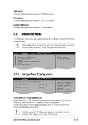
... frequency. Select either one of CPU overclocking options to malfunction. If this happens, revert to change the settings for the CPU and other system devices. ASUS P4P800-X motherboard 2-15 AMI BIOS This item displays the auto-detected BIOS information. Frequencies higher than CPU manufacturer AI Overclock Tuner [Standard] Allows selection of the...
... frequency. Select either one of CPU overclocking options to malfunction. If this happens, revert to change the settings for the CPU and other system devices. ASUS P4P800-X motherboard 2-15 AMI BIOS This item displays the auto-detected BIOS information. Frequencies higher than CPU manufacturer AI Overclock Tuner [Standard] Allows selection of the...


