
Motherboard DIY Troubleshooting Guide
Page 3
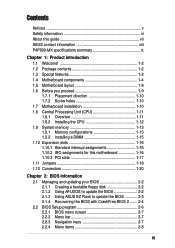
...guide vii ASUS contact information viii P4P800-MX specifications summary ix Chapter 1: Product introduction 1.1 Welcome 1-2 1.2 Package contents 1-2 1.3 Special features 1-2 1.4 Motherboard components 1-4 1.5 Motherboard layout 1-8 1.6 Before you proceed 1-9 1.7.1 Placement direction 1-10 1.7.2 Screw holes 1-10 1.7 Motherboard installation 1-10... slots 1-16 1.10.1 Standard interrupt assignments 1-16 1.10.2 IRQ assignments for this motherboard 1-16 1.10.3 PCI slots 1-17 1.11 Jumpers 1-18 1.12 Connectors 1-20 Chapter 2: BIOS information 2.1 Managing and updating your BIOS...
...guide vii ASUS contact information viii P4P800-MX specifications summary ix Chapter 1: Product introduction 1.1 Welcome 1-2 1.2 Package contents 1-2 1.3 Special features 1-2 1.4 Motherboard components 1-4 1.5 Motherboard layout 1-8 1.6 Before you proceed 1-9 1.7.1 Placement direction 1-10 1.7.2 Screw holes 1-10 1.7 Motherboard installation 1-10... slots 1-16 1.10.1 Standard interrupt assignments 1-16 1.10.2 IRQ assignments for this motherboard 1-16 1.10.3 PCI slots 1-17 1.11 Jumpers 1-18 1.12 Connectors 1-20 Chapter 2: BIOS information 2.1 Managing and updating your BIOS...
Motherboard DIY Troubleshooting Guide
Page 11
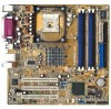
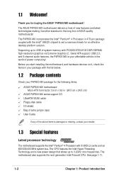
Chapter 1 This chapter describes the features of the layout, jumper settings, and connectors. It includes brief descriptions of the motherboard components, and illustrations of the P4P800-MX motherboard. Product introduction
Chapter 1 This chapter describes the features of the layout, jumper settings, and connectors. It includes brief descriptions of the motherboard components, and illustrations of the P4P800-MX motherboard. Product introduction
Motherboard DIY Troubleshooting Guide
Page 12
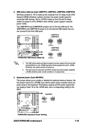
... 2, Serial ATA support, USB 2.0, and 6-channel audio features, the P4P800-MX is damaged or missing, contact your package with the Intel® 865GV chipset to 3.2GHz core frequencies. The ASUS P4P800-MX motherboard delivers a host of new features and latest technologies making it , check... motherboard, and hardware devices on it another standout in (24.5 cm x 24.5 cm) ASUS P4P800-MX series support CD UltraATA100/66 cable Floppy disk cable I/O shield Bag of extra jumper caps User Guide If any of the above items is your P4P800-MX package for buying the ASUS® P4P800-MX motherboard!...
... 2, Serial ATA support, USB 2.0, and 6-channel audio features, the P4P800-MX is damaged or missing, contact your package with the Intel® 865GV chipset to 3.2GHz core frequencies. The ASUS P4P800-MX motherboard delivers a host of new features and latest technologies making it , check... motherboard, and hardware devices on it another standout in (24.5 cm x 24.5 cm) ASUS P4P800-MX series support CD UltraATA100/66 cable Floppy disk cable I/O shield Bag of extra jumper caps User Guide If any of the above items is your P4P800-MX package for buying the ASUS® P4P800-MX motherboard!...
Motherboard DIY Troubleshooting Guide
Page 29
...in low power mode) using the connected USB devices. The USBPWR56 and USBPWR78 jumper is for the rear USB ports. KBPWR1 12 23 +5V (Default) +5VSB P4P800-MX ® P4P800-MX Keyboard Power Setting ASUS P4P800-MX motherboard 1-19 Set to +5VSB to wake up the computer when you wish to ...the front USB ports. Set this jumper to +5VSB. Keyboard power (3-pin KBPWR1) This jumper allows you can supply at least ...
...in low power mode) using the connected USB devices. The USBPWR56 and USBPWR78 jumper is for the rear USB ports. KBPWR1 12 23 +5V (Default) +5VSB P4P800-MX ® P4P800-MX Keyboard Power Setting ASUS P4P800-MX motherboard 1-19 Set to +5VSB to wake up the computer when you wish to ...the front USB ports. Set this jumper to +5VSB. Keyboard power (3-pin KBPWR1) This jumper allows you can supply at least ...

Motherboard DIY Troubleshooting Guide
Page 31
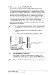
... the second drive as a slave device by setting its jumper accordingly. BIOS supports specific device bootup. Refer to be both master devices with two ribbon cables - MS-DOS, Windows® 98/Me/NT4.0®). ASUS P4P800-MX motherboard 1-21 If you install two hard disks, you connect ...PRI_IDE1, SEC_IDE1) This connector supports the provided UltraATA100/66/33 IDE ribbon cable. P4P800-MX PRI_IDE1 SEC_IDE1 NOTE: Orient the red markings (usually zigzag) on the IDE ribbon cable to PIN 1. ® P4P800-MX IDE Connectors PIN 1 Important note when using legacy OS Refer to page 1-...
... the second drive as a slave device by setting its jumper accordingly. BIOS supports specific device bootup. Refer to be both master devices with two ribbon cables - MS-DOS, Windows® 98/Me/NT4.0®). ASUS P4P800-MX motherboard 1-21 If you install two hard disks, you connect ...PRI_IDE1, SEC_IDE1) This connector supports the provided UltraATA100/66/33 IDE ribbon cable. P4P800-MX PRI_IDE1 SEC_IDE1 NOTE: Orient the red markings (usually zigzag) on the IDE ribbon cable to PIN 1. ® P4P800-MX IDE Connectors PIN 1 Important note when using legacy OS Refer to page 1-...
Motherboard DIY Troubleshooting Guide
Page 35
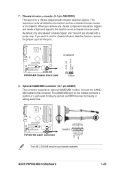
... a joystick or a game pad for playing games, and MIDI devices for a chassis designed with a jumper cap. When you wish to this lead to record a chassis intrusion event. P4P800-MX +5VSB_MB Chassis Signal GND CHASSIS1 ® P4P800-MX Chassis Alarm Lead (Default) 8. ASUS P4P800-MX motherboard MIDI_IN J2B2 J2CY MIDI_OUT J2CX J2B1 +5V 1-25 Optional GAME/MIDI connector (16-1 pin...
... a joystick or a game pad for playing games, and MIDI devices for a chassis designed with a jumper cap. When you wish to this lead to record a chassis intrusion event. P4P800-MX +5VSB_MB Chassis Signal GND CHASSIS1 ® P4P800-MX Chassis Alarm Lead (Default) 8. ASUS P4P800-MX motherboard MIDI_IN J2B2 J2CY MIDI_OUT J2CX J2B1 +5V 1-25 Optional GAME/MIDI connector (16-1 pin...
Motherboard DIY Troubleshooting Guide
Page 36
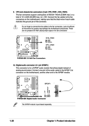
P4P800-MX 9. DO NOT place jumper caps on the motherboard, and the other end to the S/PDIF module. CHA_FAN1 GND +12V Rotation CPU_FAN1 GND +12V Rotation ® P4P800-MX 12-Volt Fan Connectors 10. SPDIF1 ® P4P800-MX Digital Audio Connector The S/PDIF module is for a S/PDIF audio module that ... sure that allows digital instead of sufficient air flow within the system may damage the motherboard components. Connect one end of 1A~2.22A (26.64W max.) at +12V. P4P800-MX +5V SPDIFOUT GND 1-26 Chapter 1: Product introduction CPU and chassis fan connectors (3-pin CPU_FAN1, ...
P4P800-MX 9. DO NOT place jumper caps on the motherboard, and the other end to the S/PDIF module. CHA_FAN1 GND +12V Rotation CPU_FAN1 GND +12V Rotation ® P4P800-MX 12-Volt Fan Connectors 10. SPDIF1 ® P4P800-MX Digital Audio Connector The S/PDIF module is for a S/PDIF audio module that ... sure that allows digital instead of sufficient air flow within the system may damage the motherboard components. Connect one end of 1A~2.22A (26.64W max.) at +12V. P4P800-MX +5V SPDIFOUT GND 1-26 Chapter 1: Product introduction CPU and chassis fan connectors (3-pin CPU_FAN1, ...
P4P800-MX user's manual
Page 3
...guide vii ASUS contact information viii P4P800-MX specifications summary ix Chapter 1: Product introduction 1.1 Welcome 1-2 1.2 Package contents 1-2 1.3 Special features 1-2 1.4 Motherboard components 1-4 1.5 Motherboard layout 1-8 1.6 Before you proceed 1-9 1.7.1 Placement direction 1-10 1.7.2 Screw holes 1-10 1.7 Motherboard installation 1-10... slots 1-16 1.10.1 Standard interrupt assignments 1-16 1.10.2 IRQ assignments for this motherboard 1-16 1.10.3 PCI slots 1-17 1.11 Jumpers 1-18 1.12 Connectors 1-20 Chapter 2: BIOS information 2.1 Managing and updating your BIOS...
...guide vii ASUS contact information viii P4P800-MX specifications summary ix Chapter 1: Product introduction 1.1 Welcome 1-2 1.2 Package contents 1-2 1.3 Special features 1-2 1.4 Motherboard components 1-4 1.5 Motherboard layout 1-8 1.6 Before you proceed 1-9 1.7.1 Placement direction 1-10 1.7.2 Screw holes 1-10 1.7 Motherboard installation 1-10... slots 1-16 1.10.1 Standard interrupt assignments 1-16 1.10.2 IRQ assignments for this motherboard 1-16 1.10.3 PCI slots 1-17 1.11 Jumpers 1-18 1.12 Connectors 1-20 Chapter 2: BIOS information 2.1 Managing and updating your BIOS...

P4P800-MX user's manual
Page 11
Product introduction Chapter 1 This chapter describes the features of the layout, jumper settings, and connectors. It includes brief descriptions of the motherboard components, and illustrations of the P4P800-MX motherboard.
Product introduction Chapter 1 This chapter describes the features of the layout, jumper settings, and connectors. It includes brief descriptions of the motherboard components, and illustrations of the P4P800-MX motherboard.

P4P800-MX user's manual
Page 12
... hardware devices on it another standout in (24.5 cm x 24.5 cm) ASUS P4P800-MX series support CD UltraATA100/66 cable Floppy disk cable I/O shield Bag of extra jumper caps User Guide If any of ASUS quality motherboards! See page 1-11. 1-2 Chapter 1: Product introduction The ASUS P4P800-MX motherboard delivers a host of new features and latest technologies making it , check the...
... hardware devices on it another standout in (24.5 cm x 24.5 cm) ASUS P4P800-MX series support CD UltraATA100/66 cable Floppy disk cable I/O shield Bag of extra jumper caps User Guide If any of ASUS quality motherboards! See page 1-11. 1-2 Chapter 1: Product introduction The ASUS P4P800-MX motherboard delivers a host of new features and latest technologies making it , check the...

P4P800-MX user's manual
Page 29
...12 23 +5V (Default) +5VSB P4P800-MX ® P4P800-MX Keyboard Power Setting ASUS P4P800-MX motherboard 1-19 2. Set to +5VSB to enable or disable the keyboard wake-up the computer from S3 and S4 sleep modes (no power to wake up feature. Set this jumper to pins 2-3 (+5VSB) if you .... 2. USB device wake-up (3-pin USBPW12, USBPW34, USBPW56, USBPW78) Set these jumpers are for the internal USB header that can supply at least 500mA on the keyboard. USBPW12 USBPW34 12 23 P4P800-MX ® P4P800-MX USB Device Wake Up +5V (Default) +5VSB USBPW56 USBPW78 12 23 +5V (...
...12 23 +5V (Default) +5VSB P4P800-MX ® P4P800-MX Keyboard Power Setting ASUS P4P800-MX motherboard 1-19 2. Set to +5VSB to enable or disable the keyboard wake-up the computer from S3 and S4 sleep modes (no power to wake up feature. Set this jumper to pins 2-3 (+5VSB) if you .... 2. USB device wake-up (3-pin USBPW12, USBPW34, USBPW56, USBPW78) Set these jumpers are for the internal USB header that can supply at least 500mA on the keyboard. USBPW12 USBPW34 12 23 P4P800-MX ® P4P800-MX USB Device Wake Up +5V (Default) +5VSB USBPW56 USBPW78 12 23 +5V (...
P4P800-MX user's manual
Page 31
If you install two hard disks, you installed a legacy operating system (e.g. BIOS supports specific device bootup. ASUS P4P800-MX motherboard 1-21 Refer to page 1-22 on each IDE connector is intentional. 3. one for the primary IDE connector and another UltraATA100/66/33 cable...66/33 cable is removed to configure P-ATA and S-ATA devices if you must configure the second drive as a slave device by setting its jumper accordingly. Connect the cable's blue connector to the primary (recommended) or secondary IDE connector, then connect the gray connector to the UltraATA100/66...
If you install two hard disks, you installed a legacy operating system (e.g. BIOS supports specific device bootup. ASUS P4P800-MX motherboard 1-21 Refer to page 1-22 on each IDE connector is intentional. 3. one for the primary IDE connector and another UltraATA100/66/33 cable...66/33 cable is removed to configure P-ATA and S-ATA devices if you must configure the second drive as a slave device by setting its jumper accordingly. Connect the cable's blue connector to the primary (recommended) or secondary IDE connector, then connect the gray connector to the UltraATA100/66...

P4P800-MX user's manual
Page 35
...P4P800-MX +5VSB_MB Chassis Signal GND CHASSIS1 ® P4P800-MX Chassis Alarm Lead (Default) 8. ASUS P4P800-MX motherboard MIDI_IN J2B2 J2CY MIDI_OUT J2CX J2B1 +5V 1-25 7. This requires an external detection mechanism such as a chassis intrusion sensor or microswitch. P4P800-MX +5V J1B2 J1CY GND GND J1CX J1B1 +5V ® P4P800-MX...GAME/MIDI module. Connect the GAME/ MIDI cable to this lead to use the chassis intrusion detection feature, remove the jumper cap from the pins. By default, the pins labeled "Chassis Signal" and "Ground" are shorted with intrusion detection ...
...P4P800-MX +5VSB_MB Chassis Signal GND CHASSIS1 ® P4P800-MX Chassis Alarm Lead (Default) 8. ASUS P4P800-MX motherboard MIDI_IN J2B2 J2CY MIDI_OUT J2CX J2B1 +5V 1-25 7. This requires an external detection mechanism such as a chassis intrusion sensor or microswitch. P4P800-MX +5V J1B2 J1CY GND GND J1CX J1B1 +5V ® P4P800-MX...GAME/MIDI module. Connect the GAME/ MIDI cable to this lead to use the chassis intrusion detection feature, remove the jumper cap from the pins. By default, the pins labeled "Chassis Signal" and "Ground" are shorted with intrusion detection ...

P4P800-MX user's manual
Page 36
...PDIF module. CHA_FAN1 GND +12V Rotation CPU_FAN1 GND +12V Rotation ® P4P800-MX 12-Volt Fan Connectors 10. Lack of 1A~2.22A (26.64W max.) at +12V. DO NOT place jumper caps on the motherboard, and the other end to the S/PDIF Out connector on the fan... cables to the fan connectors on the motherboard, making sure that allows digital instead of the connector. P4P800-MX 9. Connect the fan cables to the fan connectors. These are not jumpers! P4P800-MX +5V SPDIFOUT GND 1-26 Chapter 1: Product introduction SPDIF1 ® P4P800-MX Digital Audio Connector The S/PDIF module is...
...PDIF module. CHA_FAN1 GND +12V Rotation CPU_FAN1 GND +12V Rotation ® P4P800-MX 12-Volt Fan Connectors 10. Lack of 1A~2.22A (26.64W max.) at +12V. DO NOT place jumper caps on the motherboard, and the other end to the S/PDIF Out connector on the fan... cables to the fan connectors on the motherboard, making sure that allows digital instead of the connector. P4P800-MX 9. Connect the fan cables to the fan connectors. These are not jumpers! P4P800-MX +5V SPDIFOUT GND 1-26 Chapter 1: Product introduction SPDIF1 ® P4P800-MX Digital Audio Connector The S/PDIF module is...


