
P4B266 User Manaul
Page 3
... viii How this guide is organized viii Conventions used in this guide ix Where to find more information ix ASUS contact information x Chapter 1: Product introduction 1-1 1.1 Welcome 1-1 1.2 Package contents 1-1 1.3 Special features 1-2 ...2-1 2.1.2 Screw holes 2-1 2.2 Motherboard layout 2-2 2.3 Before you proceed 2-3 2.4 Central Processing Unit (CPU 2-4 2.4.1 Overview 2-4 2.4.2 Installing the CPU 2-5 2.4.3 Installing the heatsink and fan 2-7 2.4.4 Connecting the CPU fan cable 2-9 2.5 System memory 2-10 2.5.1 Overview 2-10 2.5.2 Memory configurations 2-11 2.5.3 Installing a ...
... viii How this guide is organized viii Conventions used in this guide ix Where to find more information ix ASUS contact information x Chapter 1: Product introduction 1-1 1.1 Welcome 1-1 1.2 Package contents 1-1 1.3 Special features 1-2 ...2-1 2.1.2 Screw holes 2-1 2.2 Motherboard layout 2-2 2.3 Before you proceed 2-3 2.4 Central Processing Unit (CPU 2-4 2.4.1 Overview 2-4 2.4.2 Installing the CPU 2-5 2.4.3 Installing the heatsink and fan 2-7 2.4.4 Connecting the CPU fan cable 2-9 2.5 System memory 2-10 2.5.1 Overview 2-10 2.5.2 Memory configurations 2-11 2.5.3 Installing a ...

P4B266 User Manaul
Page 15
...-added solutions Overclocking The P4B266 overclocking features: • adjustable CPU frequency multiple in optimization mode • adjustable CPU VCORE and DDR memory voltage ASUS iPanel support The motherboard supports the ASUS iPanel to provide easy connectivity, one-touch management of various peripherals, and convenient monitoring of system status. ASUS P4B266 motherboard user guide 1-3 The ASUS EZ Plug™...
...-added solutions Overclocking The P4B266 overclocking features: • adjustable CPU frequency multiple in optimization mode • adjustable CPU VCORE and DDR memory voltage ASUS iPanel support The motherboard supports the ASUS iPanel to provide easy connectivity, one-touch management of various peripherals, and convenient monitoring of system status. ASUS P4B266 motherboard user guide 1-3 The ASUS EZ Plug™...

P4B266 User Manaul
Page 16
...IDE connectors 9. South Bridge controller 15. Parallel port 26. ATX 12V connector 2. CPU socket 3. ASUS EZ Plug™ auxilliary +12V connector 8. Super I/O controller 11. ASUS ASIC 16. USB 2.0 controller (optional) 17. AGP slot 23. Refer to Chapter... 2 for a brief description of the motherboard specifications will also help you install the P4B266 motherboard, familiarize yourself with its components. 1.4.1 Motherboard components The following are the major components of the P4B266...
...IDE connectors 9. South Bridge controller 15. Parallel port 26. ATX 12V connector 2. CPU socket 3. ASUS EZ Plug™ auxilliary +12V connector 8. Super I/O controller 11. ASUS ASIC 16. USB 2.0 controller (optional) 17. AGP slot 23. Refer to Chapter... 2 for a brief description of the motherboard specifications will also help you install the P4B266 motherboard, familiarize yourself with its components. 1.4.1 Motherboard components The following are the major components of the P4B266...

P4B266 User Manaul
Page 18
...power supply must have an ATX +12V power supply. When this LED is lit, there is used if you press the power button. 7 ASUS EZ Plug™ Auxilliary +12V connector. Both the primary (blue) and secondary (black) connectors are interconnected through the Intel proprietary Hub interface.... Pentium® 4 478/Northwood Processor with 400MHz system bus. 3 North bridge controller. These dual-channel bus master IDE connectors support up to the CPU. 8 IDE connectors. A 478-pin surface mount, Zero Insertion Force (ZIF) socket called the Intel Memory Controller Hub (MCH) is slotted to ...
...power supply must have an ATX +12V power supply. When this LED is lit, there is used if you press the power button. 7 ASUS EZ Plug™ Auxilliary +12V connector. Both the primary (blue) and secondary (black) connectors are interconnected through the Intel proprietary Hub interface.... Pentium® 4 478/Northwood Processor with 400MHz system bus. 3 North bridge controller. These dual-channel bus master IDE connectors support up to the CPU. 8 IDE connectors. A 478-pin surface mount, Zero Insertion Force (ZIF) socket called the Intel Memory Controller Hub (MCH) is slotted to ...

P4B266 User Manaul
Page 19
... controller supports ASUS POST Reporter™ for a 360K/720K/1.44M/ 2.88M floppy disk drive, a multi-mode parallel port, two standard compatible UARTs, a Standard Infrared (SIR), one MPU-401 UART mode compatible MIDI/game port, and a Flash ROM interface. 11 DIP switches. This LED acts as a reminder to set the CPU external frequency... the rest of up if there is specifically designed for PC peripherals. (optional) 17 Onboard LED. This slot is a standby power on audio models only) ASUS P4B266 motherboard user guide 1-7
... controller supports ASUS POST Reporter™ for a 360K/720K/1.44M/ 2.88M floppy disk drive, a multi-mode parallel port, two standard compatible UARTs, a Standard Infrared (SIR), one MPU-401 UART mode compatible MIDI/game port, and a Flash ROM interface. 11 DIP switches. This LED acts as a reminder to set the CPU external frequency... the rest of up if there is specifically designed for PC peripherals. (optional) 17 Onboard LED. This slot is a standby power on audio models only) ASUS P4B266 motherboard user guide 1-7
P4B266 User Manaul
Page 26
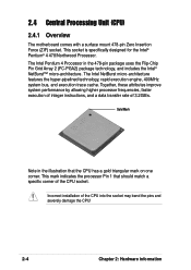
...the Intel® Pentium® 4 478/Northwood Processor. This mark indicates the processor Pin 1 that the CPU has a gold triangular mark on one corner. 2.4 Central Processing Unit (CPU) 2.4.1 Overview The motherboard comes with a surface mount 478-pin Zero Insertion Force (ZIF) socket. The ...Intel Pentium 4 Processor in the illustration that should match a specific corner of the CPU socket. Together, these attributes improve system performance by allowing higher processor frequencies, faster execution of integer instructions, and a data transfer rate...
...the Intel® Pentium® 4 478/Northwood Processor. This mark indicates the processor Pin 1 that the CPU has a gold triangular mark on one corner. 2.4 Central Processing Unit (CPU) 2.4.1 Overview The motherboard comes with a surface mount 478-pin Zero Insertion Force (ZIF) socket. The ...Intel Pentium 4 Processor in the illustration that should match a specific corner of the CPU socket. Together, these attributes improve system performance by allowing higher processor frequencies, faster execution of integer instructions, and a data transfer rate...

P4B266 User Manaul
Page 27
2.4.2 Installing the CPU Follow these steps to a 90°-100° angle. Locate the 478-pin ZIF socket on the motherboard. 2. ASUS P4B266 motherboard user guide 2-5 Unlock the socket by pressing the lever sideways, then lift it up to 90°-100° angle, otherwise the CPU does not fit in completely. Socket Lever 90 - 100 Make sure that the socket lever is lifted up to install a CPU. 1.
2.4.2 Installing the CPU Follow these steps to a 90°-100° angle. Locate the 478-pin ZIF socket on the motherboard. 2. ASUS P4B266 motherboard user guide 2-5 Unlock the socket by pressing the lever sideways, then lift it up to 90°-100° angle, otherwise the CPU does not fit in completely. Socket Lever 90 - 100 Make sure that the socket lever is lifted up to install a CPU. 1.

P4B266 User Manaul
Page 28
When the CPU is locked. 2-6 Chapter 2: Hardware information Position the CPU above the socket such that it is in place, press it fits in one correct orientation. Gold Mark 5. Carefully insert the CPU into the socket to prevent bending the pins and damaging the CPU! The CPU fits only in place. 3. The lever clicks on the socket while you push down the socket lever to indicate that its marked corner matches the base of the socket lever. 4. DO NOT force the CPU into the socket until it firmly on the side tab to secure the CPU.
When the CPU is locked. 2-6 Chapter 2: Hardware information Position the CPU above the socket such that it is in place, press it fits in one correct orientation. Gold Mark 5. Carefully insert the CPU into the socket to prevent bending the pins and damaging the CPU! The CPU fits only in place. 3. The lever clicks on the socket while you push down the socket lever to indicate that its marked corner matches the base of the socket lever. 4. DO NOT force the CPU into the socket until it firmly on the side tab to secure the CPU.

P4B266 User Manaul
Page 29
... heatsink and fan. If the instructions in this section do not have to ensure optimum thermal condition and performance. ASUS P4B266 motherboard user guide 2-7 Follow these steps to install the CPU heatsink and fan. 1. CPU Heatsink Retention Module Base Your boxed Intel Pentium 4 478/Northwood Processor package should come with installation instructions for the...
... heatsink and fan. If the instructions in this section do not have to ensure optimum thermal condition and performance. ASUS P4B266 motherboard user guide 2-7 Follow these steps to install the CPU heatsink and fan. 1. CPU Heatsink Retention Module Base Your boxed Intel Pentium 4 478/Northwood Processor package should come with installation instructions for the...

P4B266 User Manaul
Page 31
CPU Fan Connector (CPU_FAN) Don't forget to plug this connector. Hardware monitoring errors may occur if you fail to connect the CPU fan connector! 3. Push down the locks on the retention mechanism to secure the heatsink and fan to the connector on the motherboard labeled CPU_FAN. ASUS P4B266 motherboard user guide 2-9 When secure, the retention locks should point to opposite directions. 2.4.4 Connecting the CPU fan cable When the fan, heatsink, and the retention mechanism are in place, connect the CPU fan cable to the module base.
CPU Fan Connector (CPU_FAN) Don't forget to plug this connector. Hardware monitoring errors may occur if you fail to connect the CPU fan connector! 3. Push down the locks on the retention mechanism to secure the heatsink and fan to the connector on the motherboard labeled CPU_FAN. ASUS P4B266 motherboard user guide 2-9 When secure, the retention locks should point to opposite directions. 2.4.4 Connecting the CPU fan cable When the fan, heatsink, and the retention mechanism are in place, connect the CPU fan cable to the module base.

P4B266 User Manaul
Page 39
...) This jumper allows you to enable or disable the JumperFree™ mode. ASUS P4B266 motherboard user guide 2-17 Frequency Multiple 5. Frequency Selection 7. Frequency Selection 8. The JumperFree mode allows you to change CPU settings through the DIP switches. Frequency Multiple 3. Frequency Selection 10. JEN SWITCH... ® ON 1 2 3 4 5 6 7 8 9 10 ON OFF P4B266 12 Jumper Mode P4B266 JumperFree™ Mode Setting 23 Jumper ...
...) This jumper allows you to enable or disable the JumperFree™ mode. ASUS P4B266 motherboard user guide 2-17 Frequency Multiple 5. Frequency Selection 7. Frequency Selection 8. The JumperFree mode allows you to change CPU settings through the DIP switches. Frequency Multiple 3. Frequency Selection 10. JEN SWITCH... ® ON 1 2 3 4 5 6 7 8 9 10 ON OFF P4B266 12 Jumper Mode P4B266 JumperFree™ Mode Setting 23 Jumper ...

P4B266 User Manaul
Page 40
... the switches does not produce any effect. 2-18 Chapter 2: Hardware information This must be set in conjunction with the CPU Bus Frequency. ® P4B266 SWITCH P4B266 CPU Frequency Multiple Selection ON 1 2 3 4 5 6 7 8 9 10 ON 1 2 3 4 5 6 7 8 9 10 ON 1 2 3 4 5 6 7 8 9 10 ON 1 2 3 4 5 6 7 8 9 10 ON 1 2 3 4 5 6 7 8 9 10 ON 1 2 3 4 5 6 7 8 9 10 ON 1 2 3 4 5 6 7 8 9 10 ON 1 2 3 4 5 6 7 8 9 10 8.0x 10.0x 11.0x 12.... 17.0x 18.0x 19.0x 20.0x 21.0x 22.0x 23.0x 24.0x Make sure that the JEN jumper is set the CPU core:bus frequency multiple is available only on unlocked CPUs. 2.
... the switches does not produce any effect. 2-18 Chapter 2: Hardware information This must be set in conjunction with the CPU Bus Frequency. ® P4B266 SWITCH P4B266 CPU Frequency Multiple Selection ON 1 2 3 4 5 6 7 8 9 10 ON 1 2 3 4 5 6 7 8 9 10 ON 1 2 3 4 5 6 7 8 9 10 ON 1 2 3 4 5 6 7 8 9 10 ON 1 2 3 4 5 6 7 8 9 10 ON 1 2 3 4 5 6 7 8 9 10 ON 1 2 3 4 5 6 7 8 9 10 ON 1 2 3 4 5 6 7 8 9 10 8.0x 10.0x 11.0x 12.... 17.0x 18.0x 19.0x 20.0x 21.0x 22.0x 23.0x 24.0x Make sure that the JEN jumper is set the CPU core:bus frequency multiple is available only on unlocked CPUs. 2.

P4B266 User Manaul
Page 41
...ASUS P4B266 motherboard user guide 2-19 To select the CPU external frequency using the DIP switches, ensure that the JEN jumper is set to be stable. The BUS Clock multiplied by the Frequency Multiple equals the CPU's internal frequency (the advertised CPU...10 ON 1 2 3 4 5 6 7 8 9 10 ON 1 2 3 4 5 6 7 8 9 10 P4B266 CPU External Frequency Selection CPU 120MHz AGP 60MHz PCI 30MHz 125MHz 62MHz 31MHz 133MHz 66MHz 33MHz Set the CPU frequency only to send the CPU. 3. CPU frequency selection (SWITCH Switches 5-9) This option tells the clock generator what frequency to the recommended...
...ASUS P4B266 motherboard user guide 2-19 To select the CPU external frequency using the DIP switches, ensure that the JEN jumper is set to be stable. The BUS Clock multiplied by the Frequency Multiple equals the CPU's internal frequency (the advertised CPU...10 ON 1 2 3 4 5 6 7 8 9 10 ON 1 2 3 4 5 6 7 8 9 10 P4B266 CPU External Frequency Selection CPU 120MHz AGP 60MHz PCI 30MHz 125MHz 62MHz 31MHz 133MHz 66MHz 33MHz Set the CPU frequency only to send the CPU. 3. CPU frequency selection (SWITCH Switches 5-9) This option tells the clock generator what frequency to the recommended...

P4B266 User Manaul
Page 43
... S3, S4, and S5 sleep modes. Both jumpers are set to pins 1-2 (+5V) by USB 1.1 devices. USBPWR01 2 1 +5V (Default) 3 2 +5VSB ® P4B266 P4B266 USB Device Wake Up USBPWR23 12 23 +5V (Default) +5VSB The USB device wake-up . 2. Set to +5VSB to +5VSB. This feature requires a power supply... can provide at least 1A on the +5VSB lead when these jumpers to +5V to CPU, DRAM in slow refresh, power supply in low power mode) using the connected USB devices. ASUS P4B266 motherboard user guide 2-21 The total current consumed must NOT exceed the power supply capability (+5VSB...
... S3, S4, and S5 sleep modes. Both jumpers are set to pins 1-2 (+5V) by USB 1.1 devices. USBPWR01 2 1 +5V (Default) 3 2 +5VSB ® P4B266 P4B266 USB Device Wake Up USBPWR23 12 23 +5V (Default) +5VSB The USB device wake-up . 2. Set to +5VSB to +5VSB. This feature requires a power supply... can provide at least 1A on the +5VSB lead when these jumpers to +5V to CPU, DRAM in slow refresh, power supply in low power mode) using the connected USB devices. ASUS P4B266 motherboard user guide 2-21 The total current consumed must NOT exceed the power supply capability (+5VSB...

P4B266 User Manaul
Page 44
...for Pentium 4 Willamette processor, and a 1.50V to the CPU. When disabled, the allowed Vcore settings are lower. Setting to a very high core voltage may cause permanent damage to 1.75V range for the ASUS POST Reporter™ function. Speaker selector (3-pin SPEECH) ... Line Out jack (lime color) on the rear panel. ® P4B266 P4B266 Speaker Selector SPEECH 12 23 BUZZER LINEOUT (Default) 8. It is recommended that you keep the default setting (Disable). ® P4B266 OVER_VOLT 2 1 DISABLE (Default) 3 2 ENABLE P4B266 OVER_VOLT Setting 2-22 Chapter 2: Hardware information
...for Pentium 4 Willamette processor, and a 1.50V to the CPU. When disabled, the allowed Vcore settings are lower. Setting to a very high core voltage may cause permanent damage to 1.75V range for the ASUS POST Reporter™ function. Speaker selector (3-pin SPEECH) ... Line Out jack (lime color) on the rear panel. ® P4B266 P4B266 Speaker Selector SPEECH 12 23 BUZZER LINEOUT (Default) 8. It is recommended that you keep the default setting (Disable). ® P4B266 OVER_VOLT 2 1 DISABLE (Default) 3 2 ENABLE P4B266 OVER_VOLT Setting 2-22 Chapter 2: Hardware information

P4B266 User Manaul
Page 50
... to go across the onboard heat sinks instead of the expansion slots. CPU_FAN GND +12V Rotation Rotation +12V GND PWRFAN ® P4B266 CH_FAN P4B266 12-Volt Fan Connectors GND +12V Rotation 2-28 Chapter 2: Hardware information DO NOT place jumper caps on the fan manufacturer. Lack ...of 1A (12W) at +12V. CPU, Chassis, and Power Fan Connectors (3-pin CPU_FAN, PWRFAN, CH_FAN) The three fan connectors support cooling fans of 350mA (4.2 Watts...
... to go across the onboard heat sinks instead of the expansion slots. CPU_FAN GND +12V Rotation Rotation +12V GND PWRFAN ® P4B266 CH_FAN P4B266 12-Volt Fan Connectors GND +12V Rotation 2-28 Chapter 2: Hardware information DO NOT place jumper caps on the fan manufacturer. Lack ...of 1A (12W) at +12V. CPU, Chassis, and Power Fan Connectors (3-pin CPU_FAN, PWRFAN, CH_FAN) The three fan connectors support cooling fans of 350mA (4.2 Watts...

P4B266 User Manaul
Page 51
...CPU. The system may become unstable and may experience difficulty powering up if the power supply is 230W, or 300W for a fully configured system. The plugs from the power supply are using a standard ATX power supply that does not have the ATX +12V plug, connect one orientation. In addition to the ASUS... +5.0VDC GND +5.0VDC GND PWR_OK +5VSB +12.0VDC EZ_PLUG NC GND GND +12V ATX12V COM +12V DC P4B266 ATX & Auxiliary Power Connectors COM +12V DC ASUS P4B266 motherboard user guide 2-29 Find the proper orientation and push down firmly until the connectors completely fit. Make sure ...
...CPU. The system may become unstable and may experience difficulty powering up if the power supply is 230W, or 300W for a fully configured system. The plugs from the power supply are using a standard ATX power supply that does not have the ATX +12V plug, connect one orientation. In addition to the ASUS... +5.0VDC GND +5.0VDC GND PWR_OK +5VSB +12.0VDC EZ_PLUG NC GND GND +12V ATX12V COM +12V DC P4B266 ATX & Auxiliary Power Connectors COM +12V DC ASUS P4B266 motherboard user guide 2-29 Find the proper orientation and push down firmly until the connectors completely fit. Make sure ...

P4B266 User Manaul
Page 63
... system front panel case lights up. System running , the BIOS beeps or additional messages appear on . ASUS P4B266 motherboard user guide 3-1 You will not hear the BIOS beeps when the ASUS POST Reporter™ is enabled. Be sure that is working Meaning No error during POST No DRAM installed... or detected Video card not found or video card memory bad CPU overheated; For ATX power supplies, the system LED lights...
... system front panel case lights up. System running , the BIOS beeps or additional messages appear on . ASUS P4B266 motherboard user guide 3-1 You will not hear the BIOS beeps when the ASUS POST Reporter™ is enabled. Be sure that is working Meaning No error during POST No DRAM installed... or detected Video card not found or video card memory bad CPU overheated; For ATX power supplies, the system LED lights...
P4B266 User Manaul
Page 64
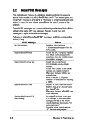
... menu." • In jumper mode, refer to support a special feature called the ASUS POST Reporter™. System failed CPU test • Check the CPU if properly installed. • Call ASUS technical support for instruction on installing a DIMM. System failed memory test • Install...you only set to section "2.3 System memory" for assistance. See the "ASUS contact information" on the DIMM sockets are not defective. • Refer to the recommended settings. POST Message Action No CPU installed • Install an Intel Pentium 4 478/Northwood Processor into the...
... menu." • In jumper mode, refer to support a special feature called the ASUS POST Reporter™. System failed CPU test • Check the CPU if properly installed. • Call ASUS technical support for instruction on installing a DIMM. System failed memory test • Install...you only set to section "2.3 System memory" for assistance. See the "ASUS contact information" on the DIMM sockets are not defective. • Refer to the recommended settings. POST Message Action No CPU installed • Install an Intel Pentium 4 478/Northwood Processor into the...

P4B266 User Manaul
Page 65
.../2 connector on the rear panel. • See section "1.3.1 Identifying the motherboard components" for assistance. ASUS P4B266 motherboard user guide 3-3 CPU fan failed • Check the CPU fan and make sure it turns on the motherboard. • See section "2.8 Connectors." See the "ASUS contact information" on the motherboard. • See section "2.8 Connectors." No floppy disk detected...
.../2 connector on the rear panel. • See section "1.3.1 Identifying the motherboard components" for assistance. ASUS P4B266 motherboard user guide 3-3 CPU fan failed • Check the CPU fan and make sure it turns on the motherboard. • See section "2.8 Connectors." See the "ASUS contact information" on the motherboard. • See section "2.8 Connectors." No floppy disk detected...


