
Motherboard DIY Troubleshooting Guide
Page 1
Motherboard ® P4B-M User Guide
Motherboard ® P4B-M User Guide

Motherboard DIY Troubleshooting Guide
Page 13
...for UltraDMA/33/66/100 IDE drives Ribbon cable for a 3.5-inch floppy drive Bag of extra jumper caps User Guide If any of the above items is your retailer. ASUS P4B-M motherboard user guide 1-1 Supporting up to 3GB of system memory with the Intel® 845 (Brookdale) chipset to get ahead... in the long line of power computing! The P4B-M incorporates the Intel® Pentium® 4 Processor in 478-pin ...
...for UltraDMA/33/66/100 IDE drives Ribbon cable for a 3.5-inch floppy drive Bag of extra jumper caps User Guide If any of the above items is your retailer. ASUS P4B-M motherboard user guide 1-1 Supporting up to 3GB of system memory with the Intel® 845 (Brookdale) chipset to get ahead... in the long line of power computing! The P4B-M incorporates the Intel® Pentium® 4 Processor in 478-pin ...
Motherboard DIY Troubleshooting Guide
Page 15
... Intel Memory Controller Hub (MCH) is slotted to set the CPU external frequency. This Low Pin Count (LPC) interface provides the commonly used Super I /O chipset. ASUS P4B-M motherboard user guide 1-3 This controller called mPGA478 B. The MCH along with 400MHz system bus. 2 North bridge controller. One side of the IDE ribbon cable. 7 Floppy disk connector. This...
... Intel Memory Controller Hub (MCH) is slotted to set the CPU external frequency. This Low Pin Count (LPC) interface provides the commonly used Super I /O chipset. ASUS P4B-M motherboard user guide 1-3 This controller called mPGA478 B. The MCH along with 400MHz system bus. 2 North bridge controller. One side of the IDE ribbon cable. 7 Floppy disk connector. This...

Motherboard DIY Troubleshooting Guide
Page 17
... mechanism that comes with the heatsink retention module base already installed. Retention Module Base Figure 1-2 Pre-installed Heatsink Retention Module Base ASUS P4B-M motherboard user guide 1-5 22 ATX 12V connector. These two 4-pin Universal Serial Bus (USB) ports are for connecting USB devices such as a...6-pin connector is shipped with a boxed CPU. This purple 6-pin connector is for a PS/2 mouse. 1.3.2 Pre-installed accessory This motherboard is for a PS/2 keyboard. 28 PS/2 mouse port. This port allows connection to remove the retention module base when installing the CPU...
... mechanism that comes with the heatsink retention module base already installed. Retention Module Base Figure 1-2 Pre-installed Heatsink Retention Module Base ASUS P4B-M motherboard user guide 1-5 22 ATX 12V connector. These two 4-pin Universal Serial Bus (USB) ports are for connecting USB devices such as a...6-pin connector is shipped with a boxed CPU. This purple 6-pin connector is for a PS/2 mouse. 1.3.2 Pre-installed accessory This motherboard is for a PS/2 keyboard. 28 PS/2 mouse port. This port allows connection to remove the retention module base when installing the CPU...

Motherboard DIY Troubleshooting Guide
Page 21
The P4B-M uses the micro-ATX form factor that the motherboard fits into it into the chassis in the correct orientation. Make sure to the rear part of the chassis. ...the motherboard to ensure that measures 9.6 inches x 9.6 inches, a standard fit for most chassis. Doing so may cause you physical injury and damage motherboard components. 2.1.1 Placement direction When installing the motherboard, make sure that you install the motherboard, study the configuration of the chassis Figure 2-1 Motherboard placement and screw holes ASUS P4B-M motherboard user guide 2-1 2.1 Motherboard ...
The P4B-M uses the micro-ATX form factor that the motherboard fits into it into the chassis in the correct orientation. Make sure to the rear part of the chassis. ...the motherboard to ensure that measures 9.6 inches x 9.6 inches, a standard fit for most chassis. Doing so may cause you physical injury and damage motherboard components. 2.1.1 Placement direction When installing the motherboard, make sure that you install the motherboard, study the configuration of the chassis Figure 2-1 Motherboard placement and screw holes ASUS P4B-M motherboard user guide 2-1 2.1 Motherboard ...
Motherboard DIY Troubleshooting Guide
Page 23
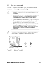
..., ensure that the system is detached from the wall socket before touching any motherboard settings. 1. P4B-M ® P4B-M Onboard LED ON Standby Power Figure 2-3 Onboard Power LED OFF Powered Off ASUS P4B-M motherboard user guide 2-3 Failure to do not to touch the ICs on a grounded antistatic pad... you install or remove any component, place it on them due to the motherboard, peripherals, and/or components. 2.3 Before you proceed Take note of the following precautions before you install motherboard components or change any component. 2. Use a grounded wrist strap or touch ...
..., ensure that the system is detached from the wall socket before touching any motherboard settings. 1. P4B-M ® P4B-M Onboard LED ON Standby Power Figure 2-3 Onboard Power LED OFF Powered Off ASUS P4B-M motherboard user guide 2-3 Failure to do not to touch the ICs on a grounded antistatic pad... you install or remove any component, place it on them due to the motherboard, peripherals, and/or components. 2.3 Before you proceed Take note of the following precautions before you install motherboard components or change any component. 2. Use a grounded wrist strap or touch ...

Motherboard DIY Troubleshooting Guide
Page 25
Locate the 478-pin ZIF socket on the motherboard. Socket Lever 90 - 100 Figure 2-6 CPU Socket Lever at 90° -100° Angle Make sure that the socket lever is lifted up to a 90°-100° angle. Unlock the socket by pressing the lever sideways, then lift it up to install a CPU. 1. 2.4.2 Installing the CPU Follow these steps to 90°-100° angle, otherwise the CPU does not fit in completely. Figure 2-5 Intel 478-pin ZIF Socket 2. ASUS P4B-M motherboard user guide 2-5
Locate the 478-pin ZIF socket on the motherboard. Socket Lever 90 - 100 Figure 2-6 CPU Socket Lever at 90° -100° Angle Make sure that the socket lever is lifted up to a 90°-100° angle. Unlock the socket by pressing the lever sideways, then lift it up to install a CPU. 1. 2.4.2 Installing the CPU Follow these steps to 90°-100° angle, otherwise the CPU does not fit in completely. Figure 2-5 Intel 478-pin ZIF Socket 2. ASUS P4B-M motherboard user guide 2-5

Motherboard DIY Troubleshooting Guide
Page 27
... 2-9 Installing the CPU Heatsink Your boxed Intel Pentium 4 478/Northwood Processor package should come with installation instructions for the CPU, heatsink, and the retention mechanism. ASUS P4B-M motherboard user guide 2-7 Follow these steps to ensure optimum thermal condition and performance. The retention module base is already installed on the retention module base. In case you...
... 2-9 Installing the CPU Heatsink Your boxed Intel Pentium 4 478/Northwood Processor package should come with installation instructions for the CPU, heatsink, and the retention mechanism. ASUS P4B-M motherboard user guide 2-7 Follow these steps to ensure optimum thermal condition and performance. The retention module base is already installed on the retention module base. In case you...

Motherboard DIY Troubleshooting Guide
Page 29
When secure, the retention locks should point to the module base. Push down the locks on the motherboard labeled CPUFAN. Figure 2-11 Fan and Retention Mechanism Installed and Locked 2.4.4 Connecting the CPU fan cable When the fan, heatsink, and the retention mechanism are in place, connect the CPU fan cable to the connector on the retention mechanism to secure the heatsink and fan to opposite directions. CPU Fan Connector (CPUFAN) Figure 2-12 CPU Fan Connector ASUS P4B-M motherboard user guide 2-9 3.
When secure, the retention locks should point to the module base. Push down the locks on the motherboard labeled CPUFAN. Figure 2-11 Fan and Retention Mechanism Installed and Locked 2.4.4 Connecting the CPU fan cable When the fan, heatsink, and the retention mechanism are in place, connect the CPU fan cable to the connector on the retention mechanism to secure the heatsink and fan to opposite directions. CPU Fan Connector (CPUFAN) Figure 2-12 CPU Fan Connector ASUS P4B-M motherboard user guide 2-9 3.

Motherboard DIY Troubleshooting Guide
Page 31
... do so may cause severe damage to both the motherboard and the components. Align a DIMM on the socket such that the notches on the DIMM match the breaks on the socket. 3. Figure 2-14 Installing a DIMM Unlocked Retaining Clip Figure 2-15 Installed DIMM ASUS P4B-M motherboard user guide Locked Retaining Clip 2-11 Unlock a DIMM socket by pressing...
... do so may cause severe damage to both the motherboard and the components. Align a DIMM on the socket such that the notches on the DIMM match the breaks on the socket. 3. Figure 2-14 Installing a DIMM Unlocked Retaining Clip Figure 2-15 Installed DIMM ASUS P4B-M motherboard user guide Locked Retaining Clip 2-11 Unlock a DIMM socket by pressing...

Motherboard DIY Troubleshooting Guide
Page 33
... slot. 5. 2.6 Expansion slots In the future, you may cause you physical injury and damage motherboard components. 2.6.1 Installing an expansion card Follow these steps to install an expansion card. 1. Make ... settings for later use . Secure the card to unplug the power cord before adding or removing expansion cards. The motherboard has three PCI slots, one Accelerated Graphics Port (AGP) slot, and a Communications and Networking Riser (CNR) slot... Remove the bracket opposite the slot that they support. Figure 2-17 Installing a PCI Card ASUS P4B-M motherboard user guide 2-13
... slot. 5. 2.6 Expansion slots In the future, you may cause you physical injury and damage motherboard components. 2.6.1 Installing an expansion card Follow these steps to install an expansion card. 1. Make ... settings for later use . Secure the card to unplug the power cord before adding or removing expansion cards. The motherboard has three PCI slots, one Accelerated Graphics Port (AGP) slot, and a Communications and Networking Riser (CNR) slot... Remove the bracket opposite the slot that they support. Figure 2-17 Installing a PCI Card ASUS P4B-M motherboard user guide 2-13

Motherboard DIY Troubleshooting Guide
Page 35
...LAN card, SCSI card, USB card, and other cards that supports +1.5V AGP cards. Figure 2-18 Installed PCI Card 2.6.4 AGP slot This motherboard has an Accelerated Graphics Port (AGP) slot that comply with +1.5V specification. Take note of a +1.5V AGP card. The following figure ...slot on a PCI slot. When you ask for 1.5V Figure 2-19 Accelerated Graphics Port (AGP) Slot Location ASUS P4B-M motherboard user guide 2-15 2.6.3 PCI slots There are three 32-bit PCI slots in this motherboard. P4B-M ® P4B-M Accelerated Graphics Port (AGP) Keyed for one with PCI specifications.
...LAN card, SCSI card, USB card, and other cards that supports +1.5V AGP cards. Figure 2-18 Installed PCI Card 2.6.4 AGP slot This motherboard has an Accelerated Graphics Port (AGP) slot that comply with +1.5V specification. Take note of a +1.5V AGP card. The following figure ...slot on a PCI slot. When you ask for 1.5V Figure 2-19 Accelerated Graphics Port (AGP) Slot Location ASUS P4B-M motherboard user guide 2-15 2.6.3 PCI slots There are three 32-bit PCI slots in this motherboard. P4B-M ® P4B-M Accelerated Graphics Port (AGP) Keyed for one with PCI specifications.

Motherboard DIY Troubleshooting Guide
Page 37
.... Frequency Selection 5. Frequencies other than the recommended CPU bus frequencies are not guaranteed to send the CPU. Frequency Selection 3. ASUS P4B-M motherboard user guide 2-17 DIP_SW P4B-M ON 12345 ON 12345 ON 12345 ON 12345 ® P4B-M CPU External Frequency Selection CPU 100MHz 105MHz 133MHz 141MHz (Default) Figure 2-22 CPU Frequency Settings Set the CPU frequency only...
.... Frequency Selection 5. Frequencies other than the recommended CPU bus frequencies are not guaranteed to send the CPU. Frequency Selection 3. ASUS P4B-M motherboard user guide 2-17 DIP_SW P4B-M ON 12345 ON 12345 ON 12345 ON 12345 ® P4B-M CPU External Frequency Selection CPU 100MHz 105MHz 133MHz 141MHz (Default) Figure 2-22 CPU Frequency Settings Set the CPU frequency only...

Motherboard DIY Troubleshooting Guide
Page 39
... Up Control). Set this jumper to pins 1-2 (+5VSB) if you to pins 2-3 activates the CNR slot. P4B-M KBPWR 2 1 +5V (Default) 3 2 +5VSB ® P4B-M Keyboard Power Setting Figure 2-25 Keyboard Power Settings ASUS P4B-M motherboard user guide 2-19 CNRUSB0 CNRUSB1 P4B-M ® P4B-M USB/CNR Selection 12 Use External USB Ports (Default) Figure 2-24 USB Port Selection 23 Use CNR...
... Up Control). Set this jumper to pins 1-2 (+5VSB) if you to pins 2-3 activates the CNR slot. P4B-M KBPWR 2 1 +5V (Default) 3 2 +5VSB ® P4B-M Keyboard Power Setting Figure 2-25 Keyboard Power Settings ASUS P4B-M motherboard user guide 2-19 CNRUSB0 CNRUSB1 P4B-M ® P4B-M USB/CNR Selection 12 Use External USB Ports (Default) Figure 2-24 USB Port Selection 23 Use CNR...

Motherboard DIY Troubleshooting Guide
Page 41
... Hub (ICH2) CLRCMOS Short the pads to re-enter data. Hold down the key during the boot process and enter BIOS setup to clear CMOS ASUS P4B-M motherboard user guide 2-21 Clear RTC RAM (CLRCMOS) These pads allow you to clear the Real Time Clock (RTC) RAM in CMOS, that include system setup information such...
... Hub (ICH2) CLRCMOS Short the pads to re-enter data. Hold down the key during the boot process and enter BIOS setup to clear CMOS ASUS P4B-M motherboard user guide 2-21 Clear RTC RAM (CLRCMOS) These pads allow you to clear the Real Time Clock (RTC) RAM in CMOS, that include system setup information such...

Motherboard DIY Troubleshooting Guide
Page 43
...Pin 20 on each IDE connector is recommended that you must configure the second drive as a slave device by setting its jumper accordingly. ASUS P4B-M motherboard user guide 2-23 If you install two hard disks, you connect non-UltraDMA/100/66 devices to the hard disk documentation for the secondary IDE ...connector. 1. The UltraDMA/66 cable included in the motherboard package also supports UltraDMA/100. Refer to the secondary IDE connector. PIN 1 For UltraDMA/100/66 IDE devices, use an 80-...
...Pin 20 on each IDE connector is recommended that you must configure the second drive as a slave device by setting its jumper accordingly. ASUS P4B-M motherboard user guide 2-23 If you install two hard disks, you connect non-UltraDMA/100/66 devices to the hard disk documentation for the secondary IDE ...connector. 1. The UltraDMA/66 cable included in the motherboard package also supports UltraDMA/100. Refer to the secondary IDE connector. PIN 1 For UltraDMA/100/66 IDE devices, use an 80-...

Motherboard DIY Troubleshooting Guide
Page 45
... Infrared Module Connector Standard Infrared (SIR) Front View Back View IRTX +5V GND (NC) IRRX ASUS P4B-M motherboard user guide 2-25 5. Connect a 2-port USB connector set UART2 for use with IR. This module mounts to an open slot in the chassis. USB23 1 5 6 10 P4B-M 1: USB Power 6: USB Power 2: USBP2- 7: USBP3- 3: USBP2+ 8: USBP3+ 4: GND 9: GND ® 5: NC...
... Infrared Module Connector Standard Infrared (SIR) Front View Back View IRTX +5V GND (NC) IRRX ASUS P4B-M motherboard user guide 2-25 5. Connect a 2-port USB connector set UART2 for use with IR. This module mounts to an open slot in the chassis. USB23 1 5 6 10 P4B-M 1: USB Power 6: USB Power 2: USBP2- 7: USBP3- 3: USBP2+ 8: USBP3+ 4: GND 9: GND ® 5: NC...

Motherboard DIY Troubleshooting Guide
Page 47
...to interface with a voice modem card with a similar connector. P4B-M HPHONE 1 Left Headphone GND Right Headphone ® P4B-M True-Level Line Out Connector Figure 2-37 Headphone True-level Line Out Connector ASUS P4B-M motherboard user guide 2-27 8. The MODEM connector allows the onboard audio to ...and a voice modem card. AUX (White) CD (Black) Left Audio Channel Ground Ground Right Audio Channel P4B-M MODEM Modem-Out Ground ® Ground Modem-In P4B-M Internal Audio Connectors Figure 2-36 Internal Audio Connectors 9. It also allows the sharing of mono_in (such as...
...to interface with a voice modem card with a similar connector. P4B-M HPHONE 1 Left Headphone GND Right Headphone ® P4B-M True-Level Line Out Connector Figure 2-37 Headphone True-level Line Out Connector ASUS P4B-M motherboard user guide 2-27 8. The MODEM connector allows the onboard audio to ...and a voice modem card. AUX (White) CD (Black) Left Audio Channel Ground Ground Right Audio Channel P4B-M MODEM Modem-Out Ground ® Ground Modem-In P4B-M Internal Audio Connectors Figure 2-36 Internal Audio Connectors 9. It also allows the sharing of mono_in (such as...

Motherboard DIY Troubleshooting Guide
Page 49
... the other end to an SPDIF module that allows digital instead of analog sound output. SERIRQ_CON P4B-M SERIRQ GND ® P4B-M SERIRQ Connector Figure 2-41 Serial IRQ Connector ASUS P4B-M motherboard user guide 2-29 This module is purchased separately. 13. Serial IRQ connector (2-pin SERIRQ_CON) (optional) This connector connects the serial IRQ onboard. 12. SPDIF_C SPDIF_OUT +5V...
... the other end to an SPDIF module that allows digital instead of analog sound output. SERIRQ_CON P4B-M SERIRQ GND ® P4B-M SERIRQ Connector Figure 2-41 Serial IRQ Connector ASUS P4B-M motherboard user guide 2-29 This module is purchased separately. 13. Serial IRQ connector (2-pin SERIRQ_CON) (optional) This connector connects the serial IRQ onboard. 12. SPDIF_C SPDIF_OUT +5V...
Motherboard DIY Troubleshooting Guide
Page 51
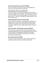
... SMI) This 2-pin connector allows you to hear system beeps and warnings. • System Message LED Lead (2-pin MSG.LED) This 2-pin connector is received. ASUS P4B-M motherboard user guide 2-31 The normal status for this 2-pin connector. • ATX Power Switch / Soft-Off Switch Lead (2-pin PWR.SW) This connector connects a switch that indicates...
... SMI) This 2-pin connector allows you to hear system beeps and warnings. • System Message LED Lead (2-pin MSG.LED) This 2-pin connector is received. ASUS P4B-M motherboard user guide 2-31 The normal status for this 2-pin connector. • ATX Power Switch / Soft-Off Switch Lead (2-pin PWR.SW) This connector connects a switch that indicates...

