
P3V4X User Manual
Page 1
® P3V4X ATX Motherboard USER'S MANUAL
® P3V4X ATX Motherboard USER'S MANUAL
P3V4X User Manual
Page 4
CONTENTS 1. FEATURES 8 2.1 The ASUS P3V4X 8 2.1.1 Specifications 8 2.1.2 Special Features 10 2.1.3 Performance Features 10 2.1.4 Intelligence 11 2.2 P3V4X Motherboard Components 12 3. HARDWARE SETUP 14 3.1 P3V4X Motherboard Layout 14 3.2 Layout Contents 15 3.3 Hardware Setup Procedure 16 3.4 Motherboard Settings 16 3.5 System Memory (DIMM 20 3.6 Central Processing Unit (CPU...Computer System 43 4.1.2 Updating BIOS Procedures (only when necessary) ......... 44 4 ASUS P3V4X User's Manual INTRODUCTION 7 1.1 How This Manual Is Organized 7 1.2 Item Checklist 7 2.
CONTENTS 1. FEATURES 8 2.1 The ASUS P3V4X 8 2.1.1 Specifications 8 2.1.2 Special Features 10 2.1.3 Performance Features 10 2.1.4 Intelligence 11 2.2 P3V4X Motherboard Components 12 3. HARDWARE SETUP 14 3.1 P3V4X Motherboard Layout 14 3.2 Layout Contents 15 3.3 Hardware Setup Procedure 16 3.4 Motherboard Settings 16 3.5 System Memory (DIMM 20 3.6 Central Processing Unit (CPU...Computer System 43 4.1.2 Updating BIOS Procedures (only when necessary) ......... 44 4 ASUS P3V4X User's Manual INTRODUCTION 7 1.1 How This Manual Is Organized 7 1.2 Item Checklist 7 2.
P3V4X User Manual
Page 5
SOFTWARE SETUP 77 5.1 Operating Systems 77 5.1.1 Windows 98 First Time Installation 77 5.2 P3V Series Motherboard Support CD 78 5.3 Install ASUS PC Probe Vx.xx 79 5.4 Install PC-Cillin 98 Vx.xx 80 5.5 Install ADOBE AcroBat Reader Vx.xx 80 5.6 VIA ... 73 4.6 Boot Menu 74 4.7 Exit Menu 75 5. APPENDIX 89 7.1 S370 Series CPU Cards 89 7.1.1 Using the ASUS S370 Series CPU Cards 90 7.1.2 Setting up the ASUS S370 Series CPU Cards 90 7.2 ASUS PCI-L101 Fast Ethernet Card 91 7.3 Glossary 93 ASUS P3V4X User's Manual 5 SOFTWARE REFERENCE 85 6.1 ASUS PC Probe 85 7.
SOFTWARE SETUP 77 5.1 Operating Systems 77 5.1.1 Windows 98 First Time Installation 77 5.2 P3V Series Motherboard Support CD 78 5.3 Install ASUS PC Probe Vx.xx 79 5.4 Install PC-Cillin 98 Vx.xx 80 5.5 Install ADOBE AcroBat Reader Vx.xx 80 5.6 VIA ... 73 4.6 Boot Menu 74 4.7 Exit Menu 75 5. APPENDIX 89 7.1 S370 Series CPU Cards 89 7.1.1 Using the ASUS S370 Series CPU Cards 90 7.1.2 Setting up the ASUS S370 Series CPU Cards 90 7.2 ASUS PCI-L101 Fast Ethernet Card 91 7.3 Glossary 93 ASUS P3V4X User's Manual 5 SOFTWARE REFERENCE 85 6.1 ASUS PC Probe 85 7.
P3V4X User Manual
Page 7
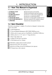
... CD with drivers and utilities (1) This Motherboard User's Manual ASUS IrDA-compliant infrared module (optional) ASUS S370 Series CPU cards (optional) ASUS PCI-L101 Wake-On-LAN 10/100 Ethernet Card (optional) CPU thermal sensor cable (optional) ASUS P3V4X User's Manual 7 If you discover damaged or missing items, contact your retailer. (1) ASUS Motherboard (1) Universal Retention Mechanism for SECC2/SECC/SEPP...
... CD with drivers and utilities (1) This Motherboard User's Manual ASUS IrDA-compliant infrared module (optional) ASUS S370 Series CPU cards (optional) ASUS PCI-L101 Wake-On-LAN 10/100 Ethernet Card (optional) CPU thermal sensor cable (optional) ASUS P3V4X User's Manual 7 If you discover damaged or missing items, contact your retailer. (1) ASUS Motherboard (1) Universal Retention Mechanism for SECC2/SECC/SEPP...

P3V4X User Manual
Page 8
...; 133/100/66MHz Front Side Bus (FSB); VC SDRAM and HSDRAM are included to allow manual adjustment of frequency through an optional ASUS PCI-L101 10/100 Fast Ethernet PCI card (see 7. Appendix). 8 ASUS P3V4X User's Manual FEATURES 2.1 The ASUS P3V4X The ASUS P3V4X motherboard is enabled. FEATURES Specifications 2. Supports UltraDMA/66, UltraDMA/33, PIO Modes 3 & 4 and Bus Master IDE...
...; 133/100/66MHz Front Side Bus (FSB); VC SDRAM and HSDRAM are included to allow manual adjustment of frequency through an optional ASUS PCI-L101 10/100 Fast Ethernet PCI card (see 7. Appendix). 8 ASUS P3V4X User's Manual FEATURES 2.1 The ASUS P3V4X The ASUS P3V4X motherboard is enabled. FEATURES Specifications 2. Supports UltraDMA/66, UltraDMA/33, PIO Modes 3 & 4 and Bus Master IDE...
P3V4X User Manual
Page 10
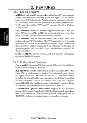
...Power Management (OSPM) functionality. This motherboard with existing DMA devices and systems so there is backward compatible with both DMA/33 and DMA and with its chipset and support for higher system performance at minimal cost premium. 10 ASUS P3V4X User's Manual FEATURES Performance 2. UltraDMA/66 is ... disk drives, expansion cards, and other devices virtually automatic. • PC'98 Compliant: Both the BIOS and hardware levels of ASUS smart series motherboards meet PC'98 compliancy. With these features implemented in the OS, PCs can handle rates up to 33MB/s. 2. The PC'98...
...Power Management (OSPM) functionality. This motherboard with existing DMA devices and systems so there is backward compatible with both DMA/33 and DMA and with its chipset and support for higher system performance at minimal cost premium. 10 ASUS P3V4X User's Manual FEATURES Performance 2. UltraDMA/66 is ... disk drives, expansion cards, and other devices virtually automatic. • PC'98 Compliant: Both the BIOS and hardware levels of ASUS smart series motherboards meet PC'98 compliancy. With these features implemented in the OS, PCs can handle rates up to 33MB/s. 2. The PC'98...
P3V4X User Manual
Page 11
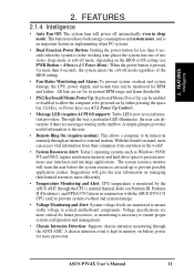
... or disabled to allow the computer to critical motherboard components. FEATURES 2.1.4 Intelligence • Auto Fan Off: The system fans will give the user information on by the ASUS ASIC through an internal or external modem. ASUS P3V4X User's Manual 11 2. With this benefit on Pentium III,... Pentium II (Deschutes), and PPGA370 Celeron in conjunction with the ASUS S370-133 CPU card) to prevent system overheat...
... or disabled to allow the computer to critical motherboard components. FEATURES 2.1.4 Intelligence • Auto Fan Off: The system fans will give the user information on by the ASUS ASIC through an internal or external modem. ASUS P3V4X User's Manual 11 2. With this benefit on Pentium III,... Pentium II (Deschutes), and PPGA370 Celeron in conjunction with the ASUS S370-133 CPU card) to prevent system overheat...
P3V4X User Manual
Page 12
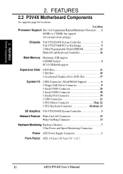
... 2. Location Processor Support Slot 1 for locations. 2. FEATURES 2.2 P3V4X Motherboard Components See opposite page for Coppermine/Katmai/Mendecino Processors ...... 2 66MHz to 150MHz bus support (16 external clock settings) Chipsets VIA VT82C694X System Controller 3 VIA VT82C596B ... 13 Hardware Monitoring Hardware Monitor 7 3 Fan Power and Speed Monitoring Connectors Power ATX Power Supply Connector 1 Form Factor ATX, 19.2cm x 30.5cm (7.6" x 12") 12 ASUS P3V4X User's Manual
... 2. Location Processor Support Slot 1 for locations. 2. FEATURES 2.2 P3V4X Motherboard Components See opposite page for Coppermine/Katmai/Mendecino Processors ...... 2 66MHz to 150MHz bus support (16 external clock settings) Chipsets VIA VT82C694X System Controller 3 VIA VT82C596B ... 13 Hardware Monitoring Hardware Monitor 7 3 Fan Power and Speed Monitoring Connectors Power ATX Power Supply Connector 1 Form Factor ATX, 19.2cm x 30.5cm (7.6" x 12") 12 ASUS P3V4X User's Manual
P3V4X User Manual
Page 13
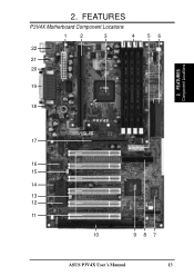
FEATURES Component Locations 17 16 15 14 13 12 11 10 987 ASUS P3V4X User's Manual 13 FEATURES P3V4X Motherboard Component Locations 1 2 3 4 22 21 20 56 19 18 2. 2.
FEATURES Component Locations 17 16 15 14 13 12 11 10 987 ASUS P3V4X User's Manual 13 FEATURES P3V4X Motherboard Component Locations 1 2 3 4 22 21 20 56 19 18 2. 2.
P3V4X User Manual
Page 14
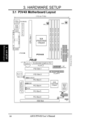
...64/72 bit, 168 pin module) DIMM Socket 3 (64/72 bit, 168 pin module) SECONDARY IDE PRIMARY IDE 30.4cm (12.0in) 3. H/W SETUP Motherboard Layout 3. HARDWARE SETUP 3.1 P3V4X Motherboard Layout 19.2cm (7.6in) T: Mouse B: Keyboard PS2KBMS USB T: USB1 B: USB2 COM1 CPU_FAN PWR_FAN PARALLEL PORT ATX Power Connector CPU Slot 1 VIA VT82C694X Chipset ...(Programable BIOS) Multi-I/O WOL_CON PCI Slot 2 CHASSIS PCI Slot 3 SMB PCI Slot 4 WOR PCI Slot 5 PCI Slot 6 ISA Slot FLOPPY VIA VT82C596B Chipset ASUS ASIC with Hardware Monitor CHA_FAN PANEL JEN IDELED IR 14 ASUS P3V4X User's Manual
...64/72 bit, 168 pin module) DIMM Socket 3 (64/72 bit, 168 pin module) SECONDARY IDE PRIMARY IDE 30.4cm (12.0in) 3. H/W SETUP Motherboard Layout 3. HARDWARE SETUP 3.1 P3V4X Motherboard Layout 19.2cm (7.6in) T: Mouse B: Keyboard PS2KBMS USB T: USB1 B: USB2 COM1 CPU_FAN PWR_FAN PARALLEL PORT ATX Power Connector CPU Slot 1 VIA VT82C694X Chipset ...(Programable BIOS) Multi-I/O WOL_CON PCI Slot 2 CHASSIS PCI Slot 3 SMB PCI Slot 4 WOR PCI Slot 5 PCI Slot 6 ISA Slot FLOPPY VIA VT82C596B Chipset ASUS ASIC with Hardware Monitor CHA_FAN PANEL JEN IDELED IR 14 ASUS P3V4X User's Manual
P3V4X User Manual
Page 15
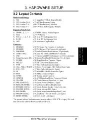
ASUS P3V4X User's Manual 15 H/W SETUP Layout Contents 3. HARDWARE SETUP 3.2 Layout Contents Motherboard Settings 1) JEN 2) U12-Switches 5 & 6 3) U12-Switches 7-10 4) U12-Switches 1-4 p. 17 JumperFree™ Mode (Enable/Disable) p. 17 AGP Bus Frequency Setting p. 18 ... IR p. 37 Infrared Port Module Connector (5 pins) 13) SMB p. 38 SMBus Connector (3 pins) 14) JTPWR p. 38 Thermal Sensor Connector 15) ATXPWR p. 39 ATX Motherboard Power Connector (20 pins) 16) CHASSIS p. 39 Chassis Intrusion Alarm Lead (4-1 pins) 17) PWR.LED (PANEL) p. 40 System Power LED Lead (3-1 pins) 18) KEYLOCK...
ASUS P3V4X User's Manual 15 H/W SETUP Layout Contents 3. HARDWARE SETUP 3.2 Layout Contents Motherboard Settings 1) JEN 2) U12-Switches 5 & 6 3) U12-Switches 7-10 4) U12-Switches 1-4 p. 17 JumperFree™ Mode (Enable/Disable) p. 17 AGP Bus Frequency Setting p. 18 ... IR p. 37 Infrared Port Module Connector (5 pins) 13) SMB p. 38 SMBus Connector (3 pins) 14) JTPWR p. 38 Thermal Sensor Connector 15) ATXPWR p. 39 ATX Motherboard Power Connector (20 pins) 16) CHASSIS p. 39 Chassis Intrusion Alarm Lead (4-1 pins) 17) PWR.LED (PANEL) p. 40 System Power LED Lead (3-1 pins) 18) KEYLOCK...
P3V4X User Manual
Page 16
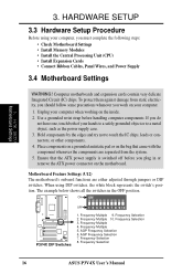
...AGP Frequency Selection 6. H/W SETUP Motherboard Settings 3. When using your computer. 1. The example below shows all the switches in or remove the ATX power connector on the inside. 2. Frequency Multiple 10. Frequency Selection 8. Frequency Selection 16 ASUS P3V4X User's Manual Ensure that came with the ...a metal object, such as the power supply case. 3. If you do not have one, touch both of your computer when working on the motherboard. ON ON P3V4X R P3V4X DIP Switches OFF 1 2 3 4 5 6 7 8 9 10 1. 3. Unplug your hands to a safely grounded object or to touch the...
...AGP Frequency Selection 6. H/W SETUP Motherboard Settings 3. When using your computer. 1. The example below shows all the switches in or remove the ATX power connector on the inside. 2. Frequency Multiple 10. Frequency Selection 8. Frequency Selection 16 ASUS P3V4X User's Manual Ensure that came with the ...a metal object, such as the power supply case. 3. If you do not have one, touch both of your computer when working on the motherboard. ON ON P3V4X R P3V4X DIP Switches OFF 1 2 3 4 5 6 7 8 9 10 1. 3. Unplug your hands to a safely grounded object or to touch the...

P3V4X User Manual
Page 17
... Freq. x1/2 P3V4X AGP Bus Frequency Setting ASUS P3V4X User's Manual 17 3. Setting JEN Enable (JumperFree) [2-3] (default) Disable (Jumper) [1-2] P3V4X R JEN 123 123 Jumper JumperFree P3V4X Jumper Mode Setting 2. x1 =DRAM Freq. NOTE: In JumperFree™ mode, all dip switches (DSW) must be set Switch 5 to OFF. AGP Bus Freq. =DRAM Freq. H/W SETUP Motherboard Settings 3. See the...
... Freq. x1/2 P3V4X AGP Bus Frequency Setting ASUS P3V4X User's Manual 17 3. Setting JEN Enable (JumperFree) [2-3] (default) Disable (Jumper) [1-2] P3V4X R JEN 123 123 Jumper JumperFree P3V4X Jumper Mode Setting 2. x1 =DRAM Freq. NOTE: In JumperFree™ mode, all dip switches (DSW) must be set Switch 5 to OFF. AGP Bus Freq. =DRAM Freq. H/W SETUP Motherboard Settings 3. See the...
P3V4X User Manual
Page 18
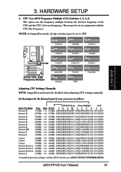
...Motherboard Settings 3. The BUS Clock multiplied by the BUS Multiple equals the CPU's Internal frequency (the advertised CPU speed). NOTE: In JumperFree mode, all dip switches must be stable. 18 ASUS P3V4X User's Manual...34MHz 1 2 3 4 5 6 7 8 9 10 112MHz 37MHz ON ON ON 1 2 3 4 5 6 7 8 9 10 CPU/DRAM PCI 68MHz 34MHz ON 1 2 3 4 5 6 7 8 9 10 100MHz 33MHz ON 1 2 3 4 5 6 7 8 9 10 120MHz 40MHz ON P3V4X 1 2 3 4 5 6 7 8 9 10 1 2 3 4 5 6 7 8 9 10 1 2 3 4 5 6 7 8 9 10 R CPU/DRAM 115MHz 110MHz 105MHz PCI 38MHz 36MHz 35MHz ON ON ON 1 2 3 4 5 6 7 8 9 10 CPU/DRAM PCI 140MHz ...
...Motherboard Settings 3. The BUS Clock multiplied by the BUS Multiple equals the CPU's Internal frequency (the advertised CPU speed). NOTE: In JumperFree mode, all dip switches must be stable. 18 ASUS P3V4X User's Manual...34MHz 1 2 3 4 5 6 7 8 9 10 112MHz 37MHz ON ON ON 1 2 3 4 5 6 7 8 9 10 CPU/DRAM PCI 68MHz 34MHz ON 1 2 3 4 5 6 7 8 9 10 100MHz 33MHz ON 1 2 3 4 5 6 7 8 9 10 120MHz 40MHz ON P3V4X 1 2 3 4 5 6 7 8 9 10 1 2 3 4 5 6 7 8 9 10 1 2 3 4 5 6 7 8 9 10 R CPU/DRAM 115MHz 110MHz 105MHz PCI 38MHz 36MHz 35MHz ON ON ON 1 2 3 4 5 6 7 8 9 10 CPU/DRAM PCI 140MHz ...
P3V4X User Manual
Page 19
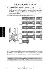
... III Pentium II/III Pentium II Pentium II (CPU BUS Freq.) (Freq. H/W SETUP Motherboard Settings Adjusting CPU Settings Manually NOTE: JumperFree mode must be set in conjunction with the CPU Bus Frequency. Set the ...][OFF] Pentium II 233MHz 3.5x 66MHz [OFF][OFF][ON][ON] [OFF][OFF][ON][ON] [ON][OFF] For updated processor settings, visit the ASUS web site (see ASUS CONTACT INFORMATION) ASUS P3V4X User's Manual 19 ON ON ON 1 2 3 4 5 6 7 8 9 10 2.0x(2/1) ON 1 2 3 4 5 6 7 8 9 10 2.5x(5/2) ON 1 2 3 4 5 6 7 8 9 10 3.0x(3/1) ON 1 2 3 4 5 6 7 8 9 10 1 2 3 4 5 6 7 8 9 10 1 2...
... III Pentium II/III Pentium II Pentium II (CPU BUS Freq.) (Freq. H/W SETUP Motherboard Settings Adjusting CPU Settings Manually NOTE: JumperFree mode must be set in conjunction with the CPU Bus Frequency. Set the ...][OFF] Pentium II 233MHz 3.5x 66MHz [OFF][OFF][ON][ON] [OFF][OFF][ON][ON] [ON][OFF] For updated processor settings, visit the ASUS web site (see ASUS CONTACT INFORMATION) ASUS P3V4X User's Manual 19 ON ON ON 1 2 3 4 5 6 7 8 9 10 2.0x(2/1) ON 1 2 3 4 5 6 7 8 9 10 2.5x(5/2) ON 1 2 3 4 5 6 7 8 9 10 3.0x(3/1) ON 1 2 3 4 5 6 7 8 9 10 1 2 3 4 5 6 7 8 9 10 1 2...
P3V4X User Manual
Page 20
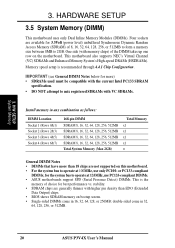
... density than 18 chips are available for best performance vs. 3. double-sided come in 32, 64, 128, 256, or 512MB. 20 ASUS P3V4X User's Manual HARDWARE SETUP 3.5 System Memory (DIMM) This motherboard uses only Dual Inline Memory Modules (DIMMs). Memory speed setup is the memory of choice for 3.3Volt (power level) unbuffered Synchronous Dynamic...
... density than 18 chips are available for best performance vs. 3. double-sided come in 32, 64, 128, 256, or 512MB. 20 ASUS P3V4X User's Manual HARDWARE SETUP 3.5 System Memory (DIMM) This motherboard uses only Dual Inline Memory Modules (DIMMs). Memory speed setup is the memory of choice for 3.3Volt (power level) unbuffered Synchronous Dynamic...
P3V4X User Manual
Page 21
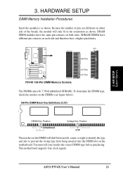
SDRAM DIMMs have different pin contacts on the motherboard. H/W SETUP System Memory DRAM Key Position RFU Unbuffered Buffered Voltage Key Position 5.0V Reserved 3.3V The notches on the DIMM will only fit in the ... below). 168-Pin DIMM Notch Key Definitions (3.3V) 3. DRAM SIMM modules have a higher pin density. This motherboard supports four clock signals. ASUS P3V4X User's Manual 21 HARDWARE SETUP DIMM Memory Installation Procedures: Insert the module(s) as shown. Lock P3V4X R P3V4X 168-Pin DIMM Memory Sockets 88 Pins 60 Pins 20 Pins The DIMMs must tell your...
SDRAM DIMMs have different pin contacts on the motherboard. H/W SETUP System Memory DRAM Key Position RFU Unbuffered Buffered Voltage Key Position 5.0V Reserved 3.3V The notches on the DIMM will only fit in the ... below). 168-Pin DIMM Notch Key Definitions (3.3V) 3. DRAM SIMM modules have a higher pin density. This motherboard supports four clock signals. ASUS P3V4X User's Manual 21 HARDWARE SETUP DIMM Memory Installation Procedures: Insert the module(s) as shown. Lock P3V4X R P3V4X 168-Pin DIMM Memory Sockets 88 Pins 60 Pins 20 Pins The DIMMs must tell your...
P3V4X User Manual
Page 23
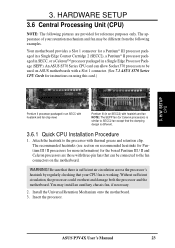
... 1. Install the Universal Retention Mechanism onto the motherboard. 3. 3. Attach the heatsink to be used on ASUS motherboards with a Slot 1 connector. (See 7.1 ASUS S370 Series CPU Cards for reference purposes only. The recommended heatsinks (see section on the motherboard. HARDWARE SETUP 3.6 Central Processing Unit (CPU) NOTE: The following examples. ASUS P3V4X User's Manual 23 Without sufficient circulation, the processor...
... 1. Install the Universal Retention Mechanism onto the motherboard. 3. 3. Attach the heatsink to be used on ASUS motherboards with a Slot 1 connector. (See 7.1 ASUS S370 Series CPU Cards for reference purposes only. The recommended heatsinks (see section on the motherboard. HARDWARE SETUP 3.6 Central Processing Unit (CPU) NOTE: The following examples. ASUS P3V4X User's Manual 23 Without sufficient circulation, the processor...
P3V4X User Manual
Page 25
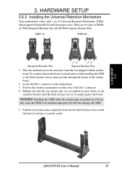
WARNING! H/W SETUP CPU ASUS P3V4X User's Manual 25 HARDWARE SETUP 3.6.3 Installing the Universal Retention Mechanism Your motherboard comes with the motherboard. Place the motherboard on the anti-static foam that the top retainer pins are not pushed in will not only ... Pins. Push the four retainer pins completely down on the motherboard. 3. Installing the URM while the retainer pins are two types of the motherboard. 2. URM (A) URM (B) Integrated Retainer Pins Separate Retainer Pins 1. Do not place the motherboard on either side of each pin is securely seated. 3....
WARNING! H/W SETUP CPU ASUS P3V4X User's Manual 25 HARDWARE SETUP 3.6.3 Installing the Universal Retention Mechanism Your motherboard comes with the motherboard. Place the motherboard on the anti-static foam that the top retainer pins are not pushed in will not only ... Pins. Push the four retainer pins completely down on the motherboard. 3. Installing the URM while the retainer pins are two types of the motherboard. 2. URM (A) URM (B) Integrated Retainer Pins Separate Retainer Pins 1. Do not place the motherboard on either side of each pin is securely seated. 3....
P3V4X User Manual
Page 26
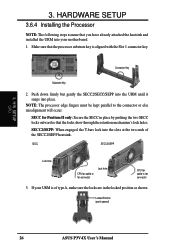
... into place. Locked Position (push upward) 26 ASUS P3V4X User's Manual Make sure that the processor substrate key is of the SECC2/SEPP heatsink. HARDWARE SETUP 3.6.4 Installing the Processor NOTE: The following steps assume that the locks show through the retention mechanism's lock holes. If your motherboard. 1. 3. Push down firmly but gently the SECC2...
... into place. Locked Position (push upward) 26 ASUS P3V4X User's Manual Make sure that the processor substrate key is of the SECC2/SEPP heatsink. HARDWARE SETUP 3.6.4 Installing the Processor NOTE: The following steps assume that the locks show through the retention mechanism's lock holes. If your motherboard. 1. 3. Push down firmly but gently the SECC2...


