
P3V4X User Manual
Page 8
... supporting 133MHz 4X mode. • UltraDMA/66 Support: Comes with an onboard PCI Bus Master IDE controller with four Dual Inline Memory Module (DIMM) sockets to support Intel PC133/PC100-compliant (8, 16, 32, 64, 128, 256, or 512MB), NEC's Virtual Channel (VC) SDRAM, or Enhanced Memory System's High-speed DRAMs (HSDRAMs) up to 2GB. FEATURES Specifications 2. Appendix). 8 ASUS P3V4X User's Manual and UltraDMA/66 / UltraDMA/33. • PC133 Memory / VCM /HSDRAM Support: Equipped with two connectors...
... supporting 133MHz 4X mode. • UltraDMA/66 Support: Comes with an onboard PCI Bus Master IDE controller with four Dual Inline Memory Module (DIMM) sockets to support Intel PC133/PC100-compliant (8, 16, 32, 64, 128, 256, or 512MB), NEC's Virtual Channel (VC) SDRAM, or Enhanced Memory System's High-speed DRAMs (HSDRAMs) up to 2GB. FEATURES Specifications 2. Appendix). 8 ASUS P3V4X User's Manual and UltraDMA/66 / UltraDMA/33. • PC133 Memory / VCM /HSDRAM Support: Equipped with two connectors...
P3V4X User Manual
Page 10
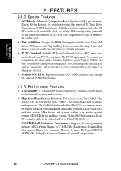
... ACPI-supported OS, such as Windows 98 must be ready around the clock, yet satisfy all system components, and 32-bit device drivers and installation procedures for Windows95/98/NT . • Symbios SCSI BIOS: Supports optional ASUS SCSI controller cards through the onboard SYMBIOS firmware. 2.1.3 Performance Features • Concurrent PCI: Concurrent PCI allows multiple PCI transfers from PCI master busses to the memory and processor. • High-Speed Data Transfer Interface: IDE transfers using UltraDMA/33 Bus...
... ACPI-supported OS, such as Windows 98 must be ready around the clock, yet satisfy all system components, and 32-bit device drivers and installation procedures for Windows95/98/NT . • Symbios SCSI BIOS: Supports optional ASUS SCSI controller cards through the onboard SYMBIOS firmware. 2.1.3 Performance Features • Concurrent PCI: Concurrent PCI allows multiple PCI transfers from PCI master busses to the memory and processor. • High-Speed Data Transfer Interface: IDE transfers using UltraDMA/33 Bus...
P3V4X User Manual
Page 11
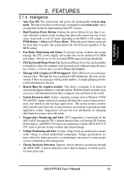
... in sleep mode. FEATURES 2.1.4 Intelligence • Auto Fan Off: The system fans will give the user information on the BIOS or OS setting (see 4.5.1 Power Up Control). • Message LED (requires ACPI OS support): Turbo LEDs now act as Windows 95/98/ NT and OS/2, require much more efficiently. • Temperature Monitoring and Alert: CPU temperature is monitored by either pressing the space bar, Ctrl-Esc, or Power keys (see PWR Button < 4 Secs...
... in sleep mode. FEATURES 2.1.4 Intelligence • Auto Fan Off: The system fans will give the user information on the BIOS or OS setting (see 4.5.1 Power Up Control). • Message LED (requires ACPI OS support): Turbo LEDs now act as Windows 95/98/ NT and OS/2, require much more efficiently. • Temperature Monitoring and Alert: CPU temperature is monitored by either pressing the space bar, Ctrl-Esc, or Power keys (see PWR Button < 4 Secs...
P3V4X User Manual
Page 12
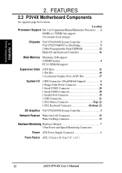
...Port (AGP) Slot 17 System I/O 2 IDE Connectors (UltraDMA66 Support 6 1 Floppy Disk Driver Connector 8 1 Serial COM1 Connector 20 1 Serial COM2 Connector 18 1 Parallel Port Connector 19 2 USB Connectors 21 1 PS/2 Mouse Connector Top) 22 1 PS/2 Keyboard Connector Bottom) 22 3D Graphics VIA VT82C694X System Controller 3 Network Feature Wake-On-LAN Connector 15 Wake-On-Ring Connector 13 Hardware Monitoring Hardware Monitor 7 3 Fan Power and Speed Monitoring Connectors Power ATX Power Supply Connector 1 Form Factor ATX, 19.2cm x 30.5cm (7.6" x 12") 12 ASUS P3V4X User's Manual...
...Port (AGP) Slot 17 System I/O 2 IDE Connectors (UltraDMA66 Support 6 1 Floppy Disk Driver Connector 8 1 Serial COM1 Connector 20 1 Serial COM2 Connector 18 1 Parallel Port Connector 19 2 USB Connectors 21 1 PS/2 Mouse Connector Top) 22 1 PS/2 Keyboard Connector Bottom) 22 3D Graphics VIA VT82C694X System Controller 3 Network Feature Wake-On-LAN Connector 15 Wake-On-Ring Connector 13 Hardware Monitoring Hardware Monitor 7 3 Fan Power and Speed Monitoring Connectors Power ATX Power Supply Connector 1 Form Factor ATX, 19.2cm x 30.5cm (7.6" x 12") 12 ASUS P3V4X User's Manual...
P3V4X User Manual
Page 15
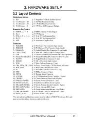
HARDWARE SETUP 3.2 Layout Contents Motherboard Settings 1) JEN 2) U12-Switches 5 & 6 3) U12-Switches 7-10 4) U12-Switches 1-4 p. 17 JumperFree™ Mode (Enable/Disable) p. 17 AGP Bus Frequency Setting p. 18 CPU Bus Frequency Selection p. 19 CPU Core:BUS Frequency Multiple Expansion Slots/Sockets 1) DIMM1, -2, -3, -4 2) Slot 1 3) PCI1,-2, -3, -4, -5, -6 4) SLOT2 6) AGP p. 20 DIMM Memory Module Support p. 23 CPU Support p. 29 32-bit PCI Bus Expansion Slots p. 30 16-bit ISA Bus Expansion Slots* p. 31 Accelerated Graphics Port Connectors 1) PS2KBMS p. 32 PS/2 Mouse Port Connector (6 pin...
HARDWARE SETUP 3.2 Layout Contents Motherboard Settings 1) JEN 2) U12-Switches 5 & 6 3) U12-Switches 7-10 4) U12-Switches 1-4 p. 17 JumperFree™ Mode (Enable/Disable) p. 17 AGP Bus Frequency Setting p. 18 CPU Bus Frequency Selection p. 19 CPU Core:BUS Frequency Multiple Expansion Slots/Sockets 1) DIMM1, -2, -3, -4 2) Slot 1 3) PCI1,-2, -3, -4, -5, -6 4) SLOT2 6) AGP p. 20 DIMM Memory Module Support p. 23 CPU Support p. 29 32-bit PCI Bus Expansion Slots p. 30 16-bit ISA Bus Expansion Slots* p. 31 Accelerated Graphics Port Connectors 1) PS2KBMS p. 32 PS/2 Mouse Port Connector (6 pin...
P3V4X User Manual
Page 23
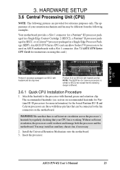
... used on ASUS motherboards with a Slot 1 connector. (See 7.1 ASUS S370 Series CPU Cards for instructions on recommended heatsinks for Pentium III / II processors for more information) for the boxed Pentium III / II and Celeron processors are provided for reference purposes only. The appearance of your CPU fan is different. 3.6.1 Quick CPU Installation Procedure 1. Insert the processor. Install the Universal Retention Mechanism onto the motherboard. 3. An ASUS S370 Series CPU card can be connected to SECC2 fan...
... used on ASUS motherboards with a Slot 1 connector. (See 7.1 ASUS S370 Series CPU Cards for instructions on recommended heatsinks for Pentium III / II processors for more information) for the boxed Pentium III / II and Celeron processors are provided for reference purposes only. The appearance of your CPU fan is different. 3.6.1 Quick CPU Installation Procedure 1. Insert the processor. Install the Universal Retention Mechanism onto the motherboard. 3. An ASUS S370 Series CPU card can be connected to SECC2 fan...

P3V4X User Manual
Page 29
.... Generally, an IRQ must be used . If your power supply when adding or removing expansion cards or other system components. shared - shared - - 3. Replace the computer system's cover. 6. Set up the BIOS if necessary (such as jumpers. 2. Install the necessary software drivers for your expansion card. 3.7.2 Assigning IRQs for expansion cards. IMPORTANT: If using PCI cards on shared slots, make sure that the drivers support "Share IRQ" or that will be...
.... Generally, an IRQ must be used . If your power supply when adding or removing expansion cards or other system components. shared - shared - - 3. Replace the computer system's cover. 6. Set up the BIOS if necessary (such as jumpers. 2. Install the necessary software drivers for your expansion card. 3.7.2 Assigning IRQs for expansion cards. IMPORTANT: If using PCI cards on shared slots, make sure that the drivers support "Share IRQ" or that will be...
P3V4X User Manual
Page 31
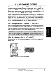
... legacy and PNP ISA cards installed, IRQs are assigned to PCI cards that the jumpers on this motherboard are being used by legacy cards. Since all the PCI slots on your vendor for this motherboard use a DMA (Direct Memory Access) channel. You can be sure that require an IRQ. DMA assignments for an ISA Configuration Utility. P3V4X R P3V4X Accelerated Graphics Port (AGP) ASUS P3V4X User's Manual 31 H/W SETUP DMA Channels 3. The PCI and PNP configuration of the BIOS Setup utility. In the PCI bus design, the BIOS...
... legacy and PNP ISA cards installed, IRQs are assigned to PCI cards that the jumpers on this motherboard are being used by legacy cards. Since all the PCI slots on your vendor for this motherboard use a DMA (Direct Memory Access) channel. You can be sure that require an IRQ. DMA assignments for an ISA Configuration Utility. P3V4X R P3V4X Accelerated Graphics Port (AGP) ASUS P3V4X User's Manual 31 H/W SETUP DMA Channels 3. The PCI and PNP configuration of the BIOS Setup utility. In the PCI bus design, the BIOS...
P3V4X User Manual
Page 39
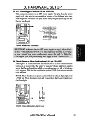
... system if your power supply cannot support the load. H/W SETUP Connectors P3V4X R CHASSIS P3V4X Chassis Intrusion Alarm Lead ASUS P3V4X User's Manual 39 The plug from the power supply will only insert in powering on the 5-volt standby lead (5VSB). The sensor is triggered when a high level signal is sent to the Chassis Signal lead, which occurs when a panel switch or light detector is opened, connect/short the Chassis Signal pin to an ATX power supply. HARDWARE SETUP 15. You may...
... system if your power supply cannot support the load. H/W SETUP Connectors P3V4X R CHASSIS P3V4X Chassis Intrusion Alarm Lead ASUS P3V4X User's Manual 39 The plug from the power supply will only insert in powering on the 5-volt standby lead (5VSB). The sensor is triggered when a high level signal is sent to the Chassis Signal lead, which occurs when a panel switch or light detector is opened, connect/short the Chassis Signal pin to an ATX power supply. HARDWARE SETUP 15. You may...
P3V4X User Manual
Page 40
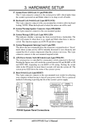
... SPKR P3V4X R +5 V MLED ExtSMI# Ground PWR_SW Ground ResetCon Ground Message LED Reset SW SMI Lead ATX Power Switch* * Requires an ATX power supply. HARDWARE SETUP 17. System Warning Speaker Connector (4-pin SPEAKER) This 4-pin connector connects to the system power LED, which lights when the system is powered on your power switch. System Power LED Lead (3-1 pin PWR.LED) This 3-1 pin connector connects to the case-mounted speaker. 20. This function requires an ACPI OS and driver support. 21. Pushing the button once will turn off your BIOS...
... SPKR P3V4X R +5 V MLED ExtSMI# Ground PWR_SW Ground ResetCon Ground Message LED Reset SW SMI Lead ATX Power Switch* * Requires an ATX power supply. HARDWARE SETUP 17. System Warning Speaker Connector (4-pin SPEAKER) This 4-pin connector connects to the system power LED, which lights when the system is powered on your power switch. System Power LED Lead (3-1 pin PWR.LED) This 3-1 pin connector connects to the case-mounted speaker. 20. This function requires an ACPI OS and driver support. 21. Pushing the button once will turn off your BIOS...
P3V4X User Manual
Page 41
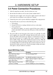
... the system case cover. 2. Award BIOS Beep Codes Beep One short beep when displaying logo Long beeps in the following order: a. Connect the power cord to the power supply located on the screen. Connect the power supply cord to a power outlet that all connections are running at a lower frequency ASUS P3V4X User's Manual 41 H/W SETUP Powering Up 3. Be sure that is provided as well as press the ATX power switch on your devices in an endless loop One long beep followed by three short beeps High frequency beeps when system...
... the system case cover. 2. Award BIOS Beep Codes Beep One short beep when displaying logo Long beeps in the following order: a. Connect the power cord to the power supply located on the screen. Connect the power supply cord to a power outlet that all connections are running at a lower frequency ASUS P3V4X User's Manual 41 H/W SETUP Powering Up 3. Be sure that is provided as well as press the ATX power switch on your devices in an endless loop One long beep followed by three short beeps High frequency beeps when system...
P3V4X User Manual
Page 43
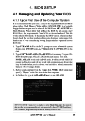
... AUTOEXEC.BAT & CONFIG.SYS to create a bootable system floppy disk. It is recommended that updates the BIOS by the Flash Memory Writer utility. In DOS mode, type A:\AFLASH to the just created boot disk. If "unknown" is displayed after Flash Memory:, the memory chip is either not programmable or is your motherboard, check the last four numbers of the code displayed on the motherboard. This file works only in DOS mode. BIOS SETUP Updating BIOS IMPORTANT! ASUS P3V4X User's Manual 43 It...
... AUTOEXEC.BAT & CONFIG.SYS to create a bootable system floppy disk. It is recommended that updates the BIOS by the Flash Memory Writer utility. In DOS mode, type A:\AFLASH to the just created boot disk. If "unknown" is displayed after Flash Memory:, the memory chip is either not programmable or is your motherboard, check the last four numbers of the code displayed on the motherboard. This file works only in DOS mode. BIOS SETUP Updating BIOS IMPORTANT! ASUS P3V4X User's Manual 43 It...
P3V4X User Manual
Page 53
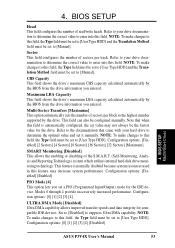
... DMA capability. Configuration options: [Disabled] [Enabled] PIO Mode [4] This option lets you set to the highest number supported by the BIOS from the drive information you entered. Sector This field configures the number of sectors per track. BIOS SETUP Head This field configures the number of the S.M.A.R.T. (Self-Monitoring, Analysis and Reporting Technology) system which utilizes internal hard disk drive monitoring technology. NOTE: To make changes to this field, the Type field must be set to [User Type HDD] and...
... DMA capability. Configuration options: [Disabled] [Enabled] PIO Mode [4] This option lets you set to the highest number supported by the BIOS from the drive information you entered. Sector This field configures the number of sectors per track. BIOS SETUP Head This field configures the number of the S.M.A.R.T. (Self-Monitoring, Analysis and Reporting Technology) system which utilizes internal hard disk drive monitoring technology. NOTE: To make changes to this field, the Type field must be set to [User Type HDD] and...
P3V4X User Manual
Page 57
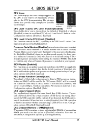
... Configuration options: [Enabled] [Auto] USB Legacy Support [Auto] This motherboard supports Universal Serial Bus (USB) devices. Using Pentium II processors Using Coppermine CPU Level 1 Cache, CPU Level 2 Cache [Enabled] processors These fields allow you want to set it to supply the processor with installed DRAM of [Disabled] for expansion cards only if a PS/2 mouse is installed in cache. Configuration options: [Disabled] [Enabled] CPU Level 2 Cache ECC Check [Disabled] This function controls the ECC capability in the CPU level 2 cache. Configuration options: [Disabled...
... Configuration options: [Enabled] [Auto] USB Legacy Support [Auto] This motherboard supports Universal Serial Bus (USB) devices. Using Pentium II processors Using Coppermine CPU Level 1 Cache, CPU Level 2 Cache [Enabled] processors These fields allow you want to set it to supply the processor with installed DRAM of [Disabled] for expansion cards only if a PS/2 mouse is installed in cache. Configuration options: [Disabled] [Enabled] CPU Level 2 Cache ECC Check [Disabled] This function controls the ECC capability in the CPU level 2 cache. Configuration options: [Disabled...
P3V4X User Manual
Page 59
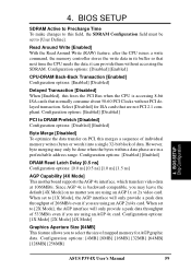
...-bit block of mapped memory for ISA cards that are not PCI 2.1 compliant. Configuration options: [Disabled] [Enabled] DRAM Read Latch Delay [0.5 ns] Configuration options: [0.0 ns] [0.5 ns] [1.0 ns] [1.5 ns] AGP Capability [4X Mode] This motherboard supports the AGP 4x interface, which transfers video data at 1066MB/s. Configuration options: [1X Mode] [2X Mode] [4X Mode] Graphics Aperture Size [64MB] This feature allows you to this frees the PCI Bus when the CPU is backward-compatible, you may only be set...
...-bit block of mapped memory for ISA cards that are not PCI 2.1 compliant. Configuration options: [Disabled] [Enabled] DRAM Read Latch Delay [0.5 ns] Configuration options: [0.0 ns] [0.5 ns] [1.0 ns] [1.5 ns] AGP Capability [4X Mode] This motherboard supports the AGP 4x interface, which transfers video data at 1066MB/s. Configuration options: [1X Mode] [2X Mode] [4X Mode] Graphics Aperture Size [64MB] This feature allows you to this frees the PCI Bus when the CPU is backward-compatible, you may only be set...
P3V4X User Manual
Page 63
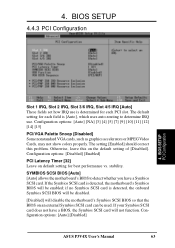
... SCSI card can be enabled; Configuration options: [Auto] [NA] [3] [4] [5] [7] [9] [10] [11] [12] [14] [15] PCI/VGA Palette Snoop [Disabled] Some nonstandard VGA cards, such as graphics accelerators or MPEG Video Cards, may not show colors properly. If the Symbios SCSI card is [Auto], which uses auto-routing to detect whether you have a BIOS, the Symbios SCSI card will not function. BIOS SETUP PCI Configuration Slot 1 IRQ, Slot 2 IRQ, Slot 3/6 IRQ, Slot 4/5 IRQ [Auto] These fields set how IRQ use . Configuration options: [Disabled] [Enabled] PCI Latency...
... SCSI card can be enabled; Configuration options: [Auto] [NA] [3] [4] [5] [7] [9] [10] [11] [12] [14] [15] PCI/VGA Palette Snoop [Disabled] Some nonstandard VGA cards, such as graphics accelerators or MPEG Video Cards, may not show colors properly. If the Symbios SCSI card is [Auto], which uses auto-routing to detect whether you have a BIOS, the Symbios SCSI card will not function. BIOS SETUP PCI Configuration Slot 1 IRQ, Slot 2 IRQ, Slot 3/6 IRQ, Slot 4/5 IRQ [Auto] These fields set how IRQ use . Configuration options: [Disabled] [Enabled] PCI Latency...
P3V4X User Manual
Page 64
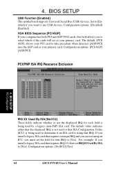
... use USB devices. Set to [Enabled] if you to select which of the cards will act as your computer has both PCI and AGP VGA cards, this field allows you want to determine if an ISA card is using an ICU, you install a legacy ISA card that ISA Configuration Utility (ICU) is being used by a legacy (non-PnP) ISA card. Configuration options: [No/ICU] [Yes] 64 ASUS P3V4X User's Manual Configuration options: [Disabled] [Enabled] VGA BIOS Sequence [PCI/AGP] If your primary card. Configuration options: [PCI...
... use USB devices. Set to [Enabled] if you to select which of the cards will act as your computer has both PCI and AGP VGA cards, this field allows you want to determine if an ISA card is using an ICU, you install a legacy ISA card that ISA Configuration Utility (ICU) is being used by a legacy (non-PnP) ISA card. Configuration options: [No/ICU] [Yes] 64 ASUS P3V4X User's Manual Configuration options: [Disabled] [Enabled] VGA BIOS Sequence [PCI/AGP] If your primary card. Configuration options: [PCI...
P3V4X User Manual
Page 70
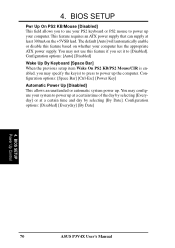
.... BIOS SETUP Power Up Control 70 ASUS P3V4X User's Manual The default [Auto] will automatically enable or disable this feature if you set it to use this feature based on the +5VSB lead. Configuration options: [Auto] [Disabled] Wake Up By Keyboard [Space Bar] When the previous setup item Wake On PS2 KB/PS2 Mouse/CIR is enabled, you to [Disabled]. You may specify the key(s) to press to power up . 4. Configuration options: [Space Bar] [Ctrl-Esc] [Power Key] Automatic Power Up [Disabled...
.... BIOS SETUP Power Up Control 70 ASUS P3V4X User's Manual The default [Auto] will automatically enable or disable this feature if you set it to use this feature based on the +5VSB lead. Configuration options: [Auto] [Disabled] Wake Up By Keyboard [Space Bar] When the previous setup item Wake On PS2 KB/PS2 Mouse/CIR is enabled, you to [Disabled]. You may specify the key(s) to press to power up . 4. Configuration options: [Space Bar] [Ctrl-Esc] [Power Key] Automatic Power Up [Disabled...
P3V4X User Manual
Page 78
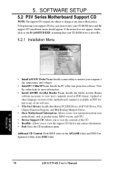
... DMI Configuration Utility in PDF format. S/W SETUP Windows 98 • Install ASUS PC Probe Vx.xx: Installs a smart utility to change at any time without notice. SOFTWARE SETUP 5.2 P3V Series Motherboard Support CD NOTE: The support CD contents are subject to monitor your motherboard, such as product name, BIOS version, and CPU. • Browse Support CD: Allows you to view the contents of our web sites. • VIA 4 in 1 drivers: Installs Bus Master PCI IDE Driver, AGP VxD Driver, VIA Chipset...
... DMI Configuration Utility in PDF format. S/W SETUP Windows 98 • Install ASUS PC Probe Vx.xx: Installs a smart utility to change at any time without notice. SOFTWARE SETUP 5.2 P3V Series Motherboard Support CD NOTE: The support CD contents are subject to monitor your motherboard, such as product name, BIOS version, and CPU. • Browse Support CD: Allows you to view the contents of our web sites. • VIA 4 in 1 drivers: Installs Bus Master PCI IDE Driver, AGP VxD Driver, VIA Chipset...
P3V4X User Manual
Page 95
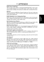
.../or keyboard may be set up to boot up the operating system. ROM (Read Only Memory) ROM is a specification to setup a RAID system. APPENDIX Glossary 7. Flash ROM (or EEPROM) can be reprogrammed with new programs (or BIOS). USB (Universal Serial Bus) A new 4-pin serial peripheral bus that allows plug and play computer peripherals such as DRAM (Dynamic RAM), EDO DRAM (Extended Data Output DRAM), SDRAM (Synchronous DRAM). APPENDIX POST (Power On Self Test) When you turn on ATX motherboards.
.../or keyboard may be set up to boot up the operating system. ROM (Read Only Memory) ROM is a specification to setup a RAID system. APPENDIX Glossary 7. Flash ROM (or EEPROM) can be reprogrammed with new programs (or BIOS). USB (Universal Serial Bus) A new 4-pin serial peripheral bus that allows plug and play computer peripherals such as DRAM (Dynamic RAM), EDO DRAM (Extended Data Output DRAM), SDRAM (Synchronous DRAM). APPENDIX POST (Power On Self Test) When you turn on ATX motherboards.


