
P3C-E User Manual
Page 4
... System Memory 22 3.5.1 Installing Memory Using RIMM/C-RIMM 23 3.5.2 Installing Memory Using an ASUS DIMM Riser ......... 24 3.6 Central Processing Unit (CPU 27 3.6.1 Universal Retention Mechanism 27 3.6.2 Heatsinks 28 3.6.3 Installing the Processor 29 3.6.4 ASUS Smart... Slot 37 3.8 External Connectors 38 3.9 Power Connection Procedures 47 4 ASUS P3C-E User's Manual CONTENTS 1. INTRODUCTION 7 1.1 How This Manual Is Organized 7 1.2 Item Checklist 7 2. FEATURES 8 2.1 The ASUS P3C-E 8 2.1.1 Specifications 8 2.1.2 Specifications-Optional Components 9 2.1.3 Performance 10 2.1.4 ...
... System Memory 22 3.5.1 Installing Memory Using RIMM/C-RIMM 23 3.5.2 Installing Memory Using an ASUS DIMM Riser ......... 24 3.6 Central Processing Unit (CPU 27 3.6.1 Universal Retention Mechanism 27 3.6.2 Heatsinks 28 3.6.3 Installing the Processor 29 3.6.4 ASUS Smart... Slot 37 3.8 External Connectors 38 3.9 Power Connection Procedures 47 4 ASUS P3C-E User's Manual CONTENTS 1. INTRODUCTION 7 1.1 How This Manual Is Organized 7 1.2 Item Checklist 7 2. FEATURES 8 2.1 The ASUS P3C-E 8 2.1.1 Specifications 8 2.1.2 Specifications-Optional Components 9 2.1.3 Performance 10 2.1.4 ...

P3C-E User Manual
Page 8
...174; II 100MHzMHz FSB SECC Intel Celeron™ 100MHz FSB SEPP • Intel 820 Chipset: Features the Intel® 820 chipset (Memory Controller Hub and I/O Controller Hub) with two connectors that support four IDE devices on two channels. 2. Easy-to-use DIP switches ... functions, especially where high bandwidth is enabled. and Intel Random Number Generator, which can transport twice the amount of the processor's external frequency. 8 ASUS P3C-E User's Manual Supports UltraDMA/66, UltraDMA/33, PIO Modes 3 & 4 and Bus Master IDE DMA Mode 2, and Enhanced IDE devices, such as...
...174; II 100MHzMHz FSB SECC Intel Celeron™ 100MHz FSB SEPP • Intel 820 Chipset: Features the Intel® 820 chipset (Memory Controller Hub and I/O Controller Hub) with two connectors that support four IDE devices on two channels. 2. Easy-to-use DIP switches ... functions, especially where high bandwidth is enabled. and Intel Random Number Generator, which can transport twice the amount of the processor's external frequency. 8 ASUS P3C-E User's Manual Supports UltraDMA/66, UltraDMA/33, PIO Modes 3 & 4 and Bus Master IDE DMA Mode 2, and Enhanced IDE devices, such as...

P3C-E User Manual
Page 9
... for wireless interfacing with EPP and ECP capabilities. Full audio output can log chassis panel open events into LDCM. FEA TURES Optional Components 2. ASUS P3C-E User's Manual 9 2. Provides Vcore and CPU/ RDRAM frequency adjustments, boot block write protection, and HD/SCSI/MO/ ZIP/CD/Floppy boot... such as SCSI or LAN cards, and one ISA slot (optional) to support legacy add-on cards. (PCI supports up to the memory and processor. 2.1.2 Specifications-Optional Components The following onboard components are optional at the time of most devices for virtually automatic setup. •...
... for wireless interfacing with EPP and ECP capabilities. Full audio output can log chassis panel open events into LDCM. FEA TURES Optional Components 2. ASUS P3C-E User's Manual 9 2. Provides Vcore and CPU/ RDRAM frequency adjustments, boot block write protection, and HD/SCSI/MO/ ZIP/CD/Floppy boot... such as SCSI or LAN cards, and one ISA slot (optional) to support legacy add-on cards. (PCI supports up to the memory and processor. 2.1.2 Specifications-Optional Components The following onboard components are optional at the time of most devices for virtually automatic setup. •...

P3C-E User Manual
Page 10
...(UltraDMA/66 requires a 40-pin 80-conductor cable to CPU. • RDRAM Optimized Performance: This motherboard supports the new generation memory, Rambus Dynamic Random Access Memory (RDRAM). The new PC 99 requirements for systems and components are based on all system components, and 32-bit device drivers and...8226; PC 99 Compliancy: Both the BIOS and hardware levels of ACPI, an ACPI-supported OS, such as required by PC 99. 10 ASUS P3C-E User's Manual To fully utilize the benefits of the motherboard meet PC 99 compliancy. This motherboard with two connectors that you do not ...
...(UltraDMA/66 requires a 40-pin 80-conductor cable to CPU. • RDRAM Optimized Performance: This motherboard supports the new generation memory, Rambus Dynamic Random Access Memory (RDRAM). The new PC 99 requirements for systems and components are based on all system components, and 32-bit device drivers and...8226; PC 99 Compliancy: Both the BIOS and hardware levels of ACPI, an ACPI-supported OS, such as required by PC 99. 10 ASUS P3C-E User's Manual To fully utilize the benefits of the motherboard meet PC 99 compliancy. This motherboard with two connectors that you do not ...
P3C-E User Manual
Page 11
Suggestions will give the user information on managing their limited resources more memory and hard drive space to be monitored for RPM and failure. Suspend or Sleep) button or as Windows 98, Windows NT, and OS/2, require much ... system configuration and management. • System Resources Alert: Today's operating systems such as the Soft-Off (see 25) ATX Power / Soft-Off Switch Lead in . ASUS P3C-E User's Manual 11 Voltage specifications are used up can be powered ON using your keyboard or mouse click. FEATURES 2.1.4 Intelligence • Fan Status Monitoring and...
Suggestions will give the user information on managing their limited resources more memory and hard drive space to be monitored for RPM and failure. Suspend or Sleep) button or as Windows 98, Windows NT, and OS/2, require much ... system configuration and management. • System Resources Alert: Today's operating systems such as the Soft-Off (see 25) ATX Power / Soft-Off Switch Lead in . ASUS P3C-E User's Manual 11 Voltage specifications are used up can be powered ON using your keyboard or mouse click. FEATURES 2.1.4 Intelligence • Fan Status Monitoring and...
P3C-E User Manual
Page 12
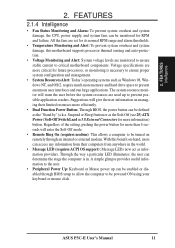
...opposite page for locations. 1 ATX Power Connector for connection to an ATX power supply 2 CPU Slot 1 3 Intel 820 Memory Controller Hub (MCH) 4 RIMM Sockets 5 Intel I/O Controller Hub (ICH) 6 Primary and Secondary IDE Connectors 7 Four ... Low Pin Count (LPC) Multi-I/O Chipset 9 Floppy Disk Drive Connector 10 Feature Setting DIP Switches 11 ASUS ASIC with Hardware Monitor 12 PCI-to-ISA Bridge 13 Wake-On-Ring Connector 14 Wake-On-LAN Connector... & USB2) 26 PS/2 Mouse (T) / PS/2 Keyboard (B) Connector T: Top B: Bottom 12 ASUS P3C-E User's Manual 2. FEA TURES Motherboard Parts 2.
...opposite page for locations. 1 ATX Power Connector for connection to an ATX power supply 2 CPU Slot 1 3 Intel 820 Memory Controller Hub (MCH) 4 RIMM Sockets 5 Intel I/O Controller Hub (ICH) 6 Primary and Secondary IDE Connectors 7 Four ... Low Pin Count (LPC) Multi-I/O Chipset 9 Floppy Disk Drive Connector 10 Feature Setting DIP Switches 11 ASUS ASIC with Hardware Monitor 12 PCI-to-ISA Bridge 13 Wake-On-Ring Connector 14 Wake-On-LAN Connector... & USB2) 26 PS/2 Mouse (T) / PS/2 Keyboard (B) Connector T: Top B: Bottom 12 ASUS P3C-E User's Manual 2. FEA TURES Motherboard Parts 2.
P3C-E User Manual
Page 14
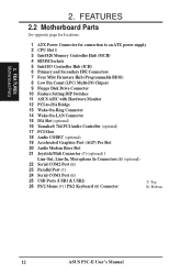
...) CPU1 (Slot 1) PARALLEL PORT OPTIONAL ATX Power Connector GAME_AUDIO COM1 Line Out Line In Mic In Audio Codec MODEM Intel 820 Memory Controller Hub (MCH) VIDEO AUX CD_IN JP10 Audio Modem Riser SPDIFIN TRCPU 1 2 RIMM0 RIMM1 3 4 Row Accelerated Graphics Port (AGP Pro... 3 (PCI3) PCI Slot 4 (PCI4) JP12 PCI Slot 5 (PCI5) PCI-to-ISA Bridge ISA Slot (SLOT2) IR DIP Switches TRPWR JP22 CHASSIS IDELED ASUS ASIC with Hardware Monitor PANEL Grayed midboard items are optional at the time of purchase. 14 ASUS P3C-E User's Manual 12345 O N 3. H/W SETUP Motherboard Layout 3.
...) CPU1 (Slot 1) PARALLEL PORT OPTIONAL ATX Power Connector GAME_AUDIO COM1 Line Out Line In Mic In Audio Codec MODEM Intel 820 Memory Controller Hub (MCH) VIDEO AUX CD_IN JP10 Audio Modem Riser SPDIFIN TRCPU 1 2 RIMM0 RIMM1 3 4 Row Accelerated Graphics Port (AGP Pro... 3 (PCI3) PCI Slot 4 (PCI4) JP12 PCI Slot 5 (PCI5) PCI-to-ISA Bridge ISA Slot (SLOT2) IR DIP Switches TRPWR JP22 CHASSIS IDELED ASUS ASIC with Hardware Monitor PANEL Grayed midboard items are optional at the time of purchase. 14 ASUS P3C-E User's Manual 12345 O N 3. H/W SETUP Motherboard Layout 3.
P3C-E User Manual
Page 15
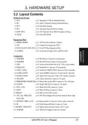
... Setting p.19 Automatic Timeout Reboot Setting p.20 CPU External Clock (BUS) Frequency Setting p.59 Clear RTC RAM Expansion Slots 1) RIMM0, RIMM1 p.22 184-Pin System Memory Support 2) CPU p.27 Central Processing Unit (CPU) 3) PCI1, PCI2, PCI3, PCI4, PCI5 p.34 32-bit PCI Bus Expansion Slots 4) AGPPRO p.36 Accelerated Graphics Port (AGP... p.44 Serial Infrared Module Connector (5-pin) 17)SPDIFIN, SPDIOOUT p.45 Digital Audio Interface Header (Two 2-pin) 18) ATXPWR p.45 ATX Power Supply Connectors (20 pins) ASUS P3C-E User's Manual 15 H/W SETUP Layout Contents 3. 3.
... Setting p.19 Automatic Timeout Reboot Setting p.20 CPU External Clock (BUS) Frequency Setting p.59 Clear RTC RAM Expansion Slots 1) RIMM0, RIMM1 p.22 184-Pin System Memory Support 2) CPU p.27 Central Processing Unit (CPU) 3) PCI1, PCI2, PCI3, PCI4, PCI5 p.34 32-bit PCI Bus Expansion Slots 4) AGPPRO p.36 Accelerated Graphics Port (AGP... p.44 Serial Infrared Module Connector (5-pin) 17)SPDIFIN, SPDIOOUT p.45 Digital Audio Interface Header (Two 2-pin) 18) ATXPWR p.45 ATX Power Supply Connectors (20 pins) ASUS P3C-E User's Manual 15 H/W SETUP Layout Contents 3. 3.
P3C-E User Manual
Page 17
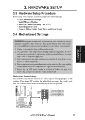
.... 4. Use a grounded wrist strap before you must complete the following steps: • Check Motherboard Settings • Install Memory Modules • Install the Central Processing Unit (CPU) • Install Expansion Cards • Connect Ribbon Cables, Panel Wires...switched off before handling computer components. H/W SETUP Motherboard Settings 3. Frequency Selection 4. Frequency Selection 1 2 3 4 P3C-E ON OFF P3C-E DIP Switches ASUS P3C-E User's Manual 17 HARDWARE SETUP 3.3 Hardware Setup Procedure Before using DIP switches, the white block represents the switch...
.... 4. Use a grounded wrist strap before you must complete the following steps: • Check Motherboard Settings • Install Memory Modules • Install the Central Processing Unit (CPU) • Install Expansion Cards • Connect Ribbon Cables, Panel Wires...switched off before handling computer components. H/W SETUP Motherboard Settings 3. Frequency Selection 4. Frequency Selection 1 2 3 4 P3C-E ON OFF P3C-E DIP Switches ASUS P3C-E User's Manual 17 HARDWARE SETUP 3.3 Hardware Setup Procedure Before using DIP switches, the white block represents the switch...

P3C-E User Manual
Page 22
... (do not use SDRAM with an SDRAM+Riser or vice versa. 22 ASUS P3C-E User's Manual For memory speed setup, see 3.5.2 Installing Memory Using the ASUS DIMM Riser). Install memory in 16, 32, 64, 128, 256, or 512MB densities can also be populated) TOTAL SYSTEM MEMORY (RDRAM: 1GB Max) / (SDRAM: 1GB Max) Subtotal x 1 x 1 = IMPORTANT 1. This assures the...
... (do not use SDRAM with an SDRAM+Riser or vice versa. 22 ASUS P3C-E User's Manual For memory speed setup, see 3.5.2 Installing Memory Using the ASUS DIMM Riser). Install memory in 16, 32, 64, 128, 256, or 512MB densities can also be populated) TOTAL SYSTEM MEMORY (RDRAM: 1GB Max) / (SDRAM: 1GB Max) Subtotal x 1 x 1 = IMPORTANT 1. This assures the...

P3C-E User Manual
Page 23
3. ASUS P3C-E User's Manual 23 IMPORTANT: Do not touch the memory module's connectors. Handle the module only by the edges. H/W SETUP System Memory EJECTOR RIBS (inside the RIMM sockets. Removing Memory 1. HARDWARE SETUP 3.5.1 Installing Memory Using RIMM/C-RIMM The memory module (RIMM/C-RIMM) will fit in place. RIMM Sockets PARALLEL PORT OPTIONAL 1 2 3 4 P3C-E RIMM with heat spreader) NOTCH KEYS...
3. ASUS P3C-E User's Manual 23 IMPORTANT: Do not touch the memory module's connectors. Handle the module only by the edges. H/W SETUP System Memory EJECTOR RIBS (inside the RIMM sockets. Removing Memory 1. HARDWARE SETUP 3.5.1 Installing Memory Using RIMM/C-RIMM The memory module (RIMM/C-RIMM) will fit in place. RIMM Sockets PARALLEL PORT OPTIONAL 1 2 3 4 P3C-E RIMM with heat spreader) NOTCH KEYS...

P3C-E User Manual
Page 24
HARDWARE SETUP 3.5.2 Installing Memory Using an ASUS DIMM Riser The ASUS DIMM Riser will fit in . If you accidentally disconnect it ...Do not rock the riser side to secure the riser in place, it is properly connected, pull it . 24 ASUS P3C-E User's Manual 3. NOTE: Hold the riser by the edges. The guides on the socket's ejectors should go through... the ejectors inward to side. If it snaps into place. RIMM0 RIMM1 PARALLEL PORT OPTIONAL P3C-E 1 2 3 4 ATTACH MOUNT BRIDGES ASUS DIMM Riser (DR2) P3C-E 184-Pin RIMM Sockets 1. Handle the riser only by its static-proof bag. Remove ...
HARDWARE SETUP 3.5.2 Installing Memory Using an ASUS DIMM Riser The ASUS DIMM Riser will fit in . If you accidentally disconnect it ...Do not rock the riser side to secure the riser in place, it is properly connected, pull it . 24 ASUS P3C-E User's Manual 3. NOTE: Hold the riser by the edges. The guides on the socket's ejectors should go through... the ejectors inward to side. If it snaps into place. RIMM0 RIMM1 PARALLEL PORT OPTIONAL P3C-E 1 2 3 4 ATTACH MOUNT BRIDGES ASUS DIMM Riser (DR2) P3C-E 184-Pin RIMM Sockets 1. Handle the riser only by its static-proof bag. Remove ...

P3C-E User Manual
Page 25
... (J1M1/J1M2) outward while holding the riser along its edges, push down gently but firmly on one on the other side. H/W SETUP System Memory 3. ASUS P3C-E User's Manual 25 Do not overtighten the captive nut. Screw the captive nuts into place and then do the same on J1M1. Doing so ...could damage your motherboard. Removing Memory from the Riser 1. If necessary, push the ejectors inward to no more than the one side of the DIMM socket (J1M1/J1M2) in place...
... (J1M1/J1M2) outward while holding the riser along its edges, push down gently but firmly on one on the other side. H/W SETUP System Memory 3. ASUS P3C-E User's Manual 25 Do not overtighten the captive nut. Screw the captive nuts into place and then do the same on J1M1. Doing so ...could damage your motherboard. Removing Memory from the Riser 1. If necessary, push the ejectors inward to no more than the one side of the DIMM socket (J1M1/J1M2) in place...

P3C-E User Manual
Page 26
...prevent the wrong type from being inserted into the DIMM socket on bootup screen. • Single-sided memory modules come in 16, 32, 64, 128, 256MB; H/W SETUP System Memory 26 ASUS P3C-E User's Manual stability. • BIOS shows your retailer the correct DIMM type before purchasing. You ...must be 3.3V Unbuffered for best performance vs. This is the memory of the strict timing issues involved under this motherboard. ...
...prevent the wrong type from being inserted into the DIMM socket on bootup screen. • Single-sided memory modules come in 16, 32, 64, 128, 256MB; H/W SETUP System Memory 26 ASUS P3C-E User's Manual stability. • BIOS shows your retailer the correct DIMM type before purchasing. You ...must be 3.3V Unbuffered for best performance vs. This is the memory of the strict timing issues involved under this motherboard. ...
P3C-E User Manual
Page 36
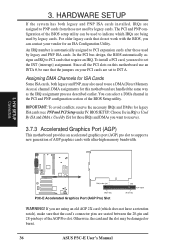
... ISA Cards Some ISA cards, both legacy and PNP ISA cards installed, IRQs are assigned to PCI cards that do not work with ultra-high memory bandwidth. 3. Otherwise, the card and the slot may also need to set to indicate which does not have a retention notch), make sure that the ... PCI Setup under IV. The PCI and PNP configuration of the AGP Pro slot. To install a PCI card, you can be damaged or burnt. 36 ASUS P3C-E User's Manual Choose Yes in the PCI and PNP configuration section of AGP graphics cards with the BIOS, you need to support a new generation of...
... ISA Cards Some ISA cards, both legacy and PNP ISA cards installed, IRQs are assigned to PCI cards that do not work with ultra-high memory bandwidth. 3. Otherwise, the card and the slot may also need to set to indicate which does not have a retention notch), make sure that the ... PCI Setup under IV. The PCI and PNP configuration of the AGP Pro slot. To install a PCI card, you can be damaged or burnt. 36 ASUS P3C-E User's Manual Choose Yes in the PCI and PNP configuration section of AGP graphics cards with the BIOS, you need to support a new generation of...
P3C-E User Manual
Page 48
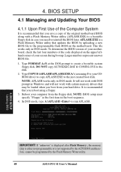
... first item in DOS mode. This file works only in the boot sequence. 4. AFLASH.EXE is a Flash Memory Writer utility that updates the BIOS by the Flash Memory Writer utility. 48 ASUS P3C-E User's Manual NOTE: AFLASH works only in case you need to reinstall the BIOS later. It will not work... with DOS prompt in Windows and will not work with a Flash Memory Writer utility (AFLASH.EXE) to the ...
... first item in DOS mode. This file works only in the boot sequence. 4. AFLASH.EXE is a Flash Memory Writer utility that updates the BIOS by the Flash Memory Writer utility. 48 ASUS P3C-E User's Manual NOTE: AFLASH works only in case you need to reinstall the BIOS later. It will not work... with DOS prompt in Windows and will not work with a Flash Memory Writer utility (AFLASH.EXE) to the ...

P3C-E User Manual
Page 50
... the new BIOS, DO NOT turn OFF your system since this happens, your system may not be updated automatically only when necessary. If the Flash Memory Writer utility was not able to boot up . If you saved to start the update. 7. BIOS SETUP Updating BIOS WARNING! The utility starts to continue... booting up. 4. When prompted to confirm the BIOS update, press Y to disk above. This will minimize the chance that a failed update will need servicing. 50 ASUS P3C-E User's Manual
... the new BIOS, DO NOT turn OFF your system since this happens, your system may not be updated automatically only when necessary. If the Flash Memory Writer utility was not able to boot up . If you saved to start the update. 7. BIOS SETUP Updating BIOS WARNING! The utility starts to continue... booting up. 4. When prompted to confirm the BIOS update, press Y to disk above. This will minimize the chance that a failed update will need servicing. 50 ASUS P3C-E User's Manual

P3C-E User Manual
Page 59
...solder points, (3) Turn ON your computer, (4) Hold down during bootup. CLRTC Short solder points P3C-E to Clear CMOS P3C-E Clear RTC RAM Halt On [All Errors] This field determines which types of conventional memory detected by erasing the CMOS Real Time Clock (RTC) RAM. 4. If you forgot the ...by the onboard button cell battery. BIOS SETUP Main Menu ASUS P3C-E User's Manual 59 BIOS SETUP Forgot the password? Configuration options: [All Errors] [No Error] [All but Keyboard] [All but Disk] [All but Disk/Keyboard] Installed Memory [XXX MB] This field displays the amount of errors ...
...solder points, (3) Turn ON your computer, (4) Hold down during bootup. CLRTC Short solder points P3C-E to Clear CMOS P3C-E Clear RTC RAM Halt On [All Errors] This field determines which types of conventional memory detected by erasing the CMOS Real Time Clock (RTC) RAM. 4. If you forgot the ...by the onboard button cell battery. BIOS SETUP Main Menu ASUS P3C-E User's Manual 59 BIOS SETUP Forgot the password? Configuration options: [All Errors] [No Error] [All but Keyboard] [All but Disk] [All but Disk/Keyboard] Installed Memory [XXX MB] This field displays the amount of errors ...

P3C-E User Manual
Page 60
... synchronous or asynchronous mode with CPU Bus Frequency to select the internal speed of 15 CPU Bus Frequency selections. Each of the two memory data transfer methods leads to the CPU Bus Frequency. Configuration options: [Manual] [300MHz] [350MHz]...[800MHz] [866MHz] CPU Frequency Multiple... memory clock frequency is locked, setting the Frequency Multiple here will be set in conjunction with respect to a set of your processor's Frequency Multiple is set to the CPU, DRAM, and chipset. The configuration options vary depending on the CPU/PCI Frequency Ratio. 60 ASUS P3C...
... synchronous or asynchronous mode with CPU Bus Frequency to select the internal speed of 15 CPU Bus Frequency selections. Each of the two memory data transfer methods leads to the CPU Bus Frequency. Configuration options: [Manual] [300MHz] [350MHz]...[800MHz] [866MHz] CPU Frequency Multiple... memory clock frequency is locked, setting the Frequency Multiple here will be set in conjunction with respect to a set of your processor's Frequency Multiple is set to the CPU, DRAM, and chipset. The configuration options vary depending on the CPU/PCI Frequency Ratio. 60 ASUS P3C...

P3C-E User Manual
Page 61
4. If detected, the USB controller will be disabled. When this option to [Enabled]; BIOS SETUP Chip Configuration ASUS P3C-E User's Manual 61 If you want to set to [Disabled], the USB controller is disabled no matter whether you to detect a USB device on... either be RDRAM Frequency (MHz) or SDRAM Frequency (MHz). The default of [Disabled] for greater anonymity. Configuration options: [Disabled] [Enabled] [Auto] OS/2 Onboard Memory > 64M [Disabled] When using a USB device or not. BIOS SETUP CPU Vcore [2.00V] (when CPU Internal Frequency is set this field is added to every...
4. If detected, the USB controller will be disabled. When this option to [Enabled]; BIOS SETUP Chip Configuration ASUS P3C-E User's Manual 61 If you want to set to [Disabled], the USB controller is disabled no matter whether you to detect a USB device on... either be RDRAM Frequency (MHz) or SDRAM Frequency (MHz). The default of [Disabled] for greater anonymity. Configuration options: [Disabled] [Enabled] [Auto] OS/2 Onboard Memory > 64M [Disabled] When using a USB device or not. BIOS SETUP CPU Vcore [2.00V] (when CPU Internal Frequency is set this field is added to every...


