
P3B-F User Manual
Page 1
® P3B-F Pentium® III / II / CeleronTM Motherboard USER'S MANUAL
® P3B-F Pentium® III / II / CeleronTM Motherboard USER'S MANUAL
P3B-F User Manual
Page 4
... 14 3.2 Layout Contents 15 3.3 Hardware Setup Procedure 16 3.4 Motherboard Settings 16 3.5 System Memory (DIMM 21 3.5.1 General DIMM Notes 21 3.5.2 DIMM Memory Installation 22 3.6 Central Processing Unit (...Assigning DMA Channels for ISA Cards 31 3.8 External Connectors 32 3.9 Power Connection Procedures 41 4. FEATURES 8 2.1 The ASUS P3B-F Motherboard 8 2.1.1 Specifications 8 2.1.2 Special Features 10 2.1.3 Performance Features 10 2.1.4 Intelligence 11 2.2 Motherboard Parts 12 3. BIOS SETUP 42 4.1 Managing and Updating Your BIOS 42 4.1.1 Upon First Use of the Computer System ...
... 14 3.2 Layout Contents 15 3.3 Hardware Setup Procedure 16 3.4 Motherboard Settings 16 3.5 System Memory (DIMM 21 3.5.1 General DIMM Notes 21 3.5.2 DIMM Memory Installation 22 3.6 Central Processing Unit (...Assigning DMA Channels for ISA Cards 31 3.8 External Connectors 32 3.9 Power Connection Procedures 41 4. FEATURES 8 2.1 The ASUS P3B-F Motherboard 8 2.1.1 Specifications 8 2.1.2 Special Features 10 2.1.3 Performance Features 10 2.1.4 Intelligence 11 2.2 Motherboard Parts 12 3. BIOS SETUP 42 4.1 Managing and Updating Your BIOS 42 4.1.1 Upon First Use of the Computer System ...

P3B-F User Manual
Page 7
...package is divided into the following sections: 1. Appendix Optional items 1.2 Item Checklist Please check that your retailer. (1) ASUS Motherboard (1) Universal Retention Mechanism for SECC2/SECC/SEPP processors (1) Ribbon cable for master and slave IDE drives (1) Ribbon cable...caps (1) Support CD with drivers and utilities (1) This Motherboard User's Manual ASUS IrDA-compliant infrared module (optional) ASUS S370 Series CPU cards (optional) ASUS PCI-L101 Wake-On-LAN 10/100 ethernet card (optional) ASUS P3B-F User's Manual 7 Features Information and specifications concerning this...
...package is divided into the following sections: 1. Appendix Optional items 1.2 Item Checklist Please check that your retailer. (1) ASUS Motherboard (1) Universal Retention Mechanism for SECC2/SECC/SEPP processors (1) Ribbon cable for master and slave IDE drives (1) Ribbon cable...caps (1) Support CD with drivers and utilities (1) This Motherboard User's Manual ASUS IrDA-compliant infrared module (optional) ASUS S370 Series CPU cards (optional) ASUS PCI-L101 Wake-On-LAN 10/100 ethernet card (optional) ASUS P3B-F User's Manual 7 Features Information and specifications concerning this...

P3B-F User Manual
Page 8
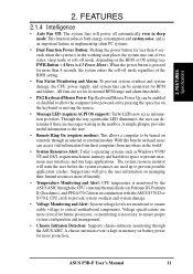
These new SDRAMs are provided to 1024MB. FEATURES 2.1 The ASUS P3B-F Motherboard The ASUS P3B-F is carefully designed for the demanding PC user who wants advanced features processed by the fastest CPU. 2.1.1 Specifications • Multi-Speed: Supports... from sleep or soft-off mode. • PC Health Monitoring: Provides an easier way to physically transport commands and information between SMBus devices. 8 ASUS P3B-F User's Manual 2. FEA TURES Specifications 2. Power supply is used to examine and manage system status information, such as CPU and system voltages, temperatures...
These new SDRAMs are provided to 1024MB. FEATURES 2.1 The ASUS P3B-F Motherboard The ASUS P3B-F is carefully designed for the demanding PC user who wants advanced features processed by the fastest CPU. 2.1.1 Specifications • Multi-Speed: Supports... from sleep or soft-off mode. • PC Health Monitoring: Provides an easier way to physically transport commands and information between SMBus devices. 8 ASUS P3B-F User's Manual 2. FEA TURES Specifications 2. Power supply is used to examine and manage system status information, such as CPU and system voltages, temperatures...

P3B-F User Manual
Page 9
...) or a CeleronTM processor packaged in a Single Edge Processor Package (SEPP). • Wake-On-LAN Connector: Supports Wake-On-LAN activity through an optional ASUS PCI-L101 10/100 Fast Ethernet PCI card (see 7.1 PCI-L101 Fast Ethernet Card) or a similar ethernet card. • Wake-On-Ring Connector: ... cards, such as not to damage the motherboard, peripherals, and/or components. FEATURES • PCI & ISA Expansion Slots: Provides options of five 32-bit PCI (rev 2.2) with two 16-bit ISA expansion slots, six PCI with one parallel port with no ISA. ASUS P3B-F User's Manual 9 This acts as a...
...) or a CeleronTM processor packaged in a Single Edge Processor Package (SEPP). • Wake-On-LAN Connector: Supports Wake-On-LAN activity through an optional ASUS PCI-L101 10/100 Fast Ethernet PCI card (see 7.1 PCI-L101 Fast Ethernet Card) or a similar ethernet card. • Wake-On-Ring Connector: ... cards, such as not to damage the motherboard, peripherals, and/or components. FEATURES • PCI & ISA Expansion Slots: Provides options of five 32-bit PCI (rev 2.2) with two 16-bit ISA expansion slots, six PCI with one parallel port with no ISA. ASUS P3B-F User's Manual 9 This acts as a...

P3B-F User Manual
Page 10
... multiple PCI transfers from PCI master busses to the memory and processor. • Double the IDE Transfer Speed: ASUS smart series motherboards with Intel chipsets improve IDE transfer rate using PC100-compliant SDRAM. 10 ASUS P3B-F User's Manual ISA cards may fail to work coming out of STR mode). • Easy Installation: Incorporates BIOS.... With these features implemented in the OS, PCs can be used. • Suspend and Go: Suspend-to-RAM (STR) provides maximum power savings (average of ASUS smart series motherboards meet PC'99 compliancy. FEA TURES Specifications 2.
... multiple PCI transfers from PCI master busses to the memory and processor. • Double the IDE Transfer Speed: ASUS smart series motherboards with Intel chipsets improve IDE transfer rate using PC100-compliant SDRAM. 10 ASUS P3B-F User's Manual ISA cards may fail to work coming out of STR mode). • Easy Installation: Incorporates BIOS.... With these features implemented in the OS, PCs can be used. • Suspend and Go: Suspend-to-RAM (STR) provides maximum power savings (average of ASUS smart series motherboards meet PC'99 compliancy. FEA TURES Specifications 2.
P3B-F User Manual
Page 11
...and hard drive space to be monitored for more efficiently. • Temperature Monitoring and Alert: CPU temperature is necessary to critical motherboard components. Through the way a particular LED illuminates, the user can be enabled or disabled to allow the computer to prevent ...4 seconds when the system is kept in memory on Pentium III, Pentium II (Deschutes), and PPGA370 Celeron in 4.5 Power Menu). ASUS P3B-F User's Manual 11 Voltage specifications are monitored to ensure stable voltage to ensure proper system configuration and management. • Chassis Intrusion ...
...and hard drive space to be monitored for more efficiently. • Temperature Monitoring and Alert: CPU temperature is necessary to critical motherboard components. Through the way a particular LED illuminates, the user can be enabled or disabled to allow the computer to prevent ...4 seconds when the system is kept in memory on Pentium III, Pentium II (Deschutes), and PPGA370 Celeron in 4.5 Power Menu). ASUS P3B-F User's Manual 11 Voltage specifications are monitored to ensure stable voltage to ensure proper system configuration and management. • Chassis Intrusion ...

P3B-F User Manual
Page 12
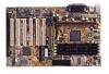
2. FEA TURES Specifications 2. FEATURES 2.2 Motherboard Parts 1 ATX Power Connector 2 Slot 1 CPU Socket 3 Intel 440BX AGPset 4 4 DIMM Sockets 5 IDE Connectors 6 ASUS ASIC with hardware monitor 7 Floppy Disk Drive Connector 8 Function DIP Switches 9 Intel PIIX4E PCIset 10 Onboard LED 11 Wake-On-Ring Connector 12 1 or 2 ISA ... Graphics Port 18 Serial Port Connector 19 Parallel Port Connector 20 Serial Port Connector 21 2 USB Connectors 22 T: PS/2 Mouse Connector B: PS/2 Keyboard Connector 12 ASUS P3B-F User's Manual
2. FEA TURES Specifications 2. FEATURES 2.2 Motherboard Parts 1 ATX Power Connector 2 Slot 1 CPU Socket 3 Intel 440BX AGPset 4 4 DIMM Sockets 5 IDE Connectors 6 ASUS ASIC with hardware monitor 7 Floppy Disk Drive Connector 8 Function DIP Switches 9 Intel PIIX4E PCIset 10 Onboard LED 11 Wake-On-Ring Connector 12 1 or 2 ISA ... Graphics Port 18 Serial Port Connector 19 Parallel Port Connector 20 Serial Port Connector 21 2 USB Connectors 22 T: PS/2 Mouse Connector B: PS/2 Keyboard Connector 12 ASUS P3B-F User's Manual

P3B-F User Manual
Page 13
2. FEATURES 12 3 4 5 22 21 20 19 18 2. FEA TURES Motherboard Parts 17 16 15 14 13 12 11 10 9 8 7 6 ASUS P3B-F User's Manual 13
2. FEATURES 12 3 4 5 22 21 20 19 18 2. FEA TURES Motherboard Parts 17 16 15 14 13 12 11 10 9 8 7 6 ASUS P3B-F User's Manual 13

P3B-F User Manual
Page 14
... 2 3 4 5 6 7 CR2032 3V Lithium Cell (CMOS Power) Accelerated Graphics Port PCI Slot 1 DIP Switches DSW R P3B-F Flash EEPROM (Programable BIOS) Multi-I/O Wake-On-LAN Connector (WOL_CON) PCI Slot 2 CHASSIS PCI Slot 3 SMB WOR PCI Slot...optional at the time of purchase.) FLOPPY Intel PIIX4E PCIset CLRTC ASUS ASIC with Hardware Monitor CHA_FAN PANEL JEN IDELED IR 14 ASUS P3B-F User's Manual 3. HARDWARE SETUP 3.1 Motherboard Layout PS2 TOP: Mouse ATXPWR KBMS BOTTOM: Keyboard TOP: USB ... 168 pin module) SECONDARY IDE PRIMARY IDE Printer Port ATX Power Connector Slot 1 3.
... 2 3 4 5 6 7 CR2032 3V Lithium Cell (CMOS Power) Accelerated Graphics Port PCI Slot 1 DIP Switches DSW R P3B-F Flash EEPROM (Programable BIOS) Multi-I/O Wake-On-LAN Connector (WOL_CON) PCI Slot 2 CHASSIS PCI Slot 3 SMB WOR PCI Slot...optional at the time of purchase.) FLOPPY Intel PIIX4E PCIset CLRTC ASUS ASIC with Hardware Monitor CHA_FAN PANEL JEN IDELED IR 14 ASUS P3B-F User's Manual 3. HARDWARE SETUP 3.1 Motherboard Layout PS2 TOP: Mouse ATXPWR KBMS BOTTOM: Keyboard TOP: USB ... 168 pin module) SECONDARY IDE PRIMARY IDE Printer Port ATX Power Connector Slot 1 3.

P3B-F User Manual
Page 15
3. HARDWARE SETUP 3.2 Layout Contents Motherboard Settings 1) DSW-Switch 6 2) DSW-Switches 7-10 3) DSW-Switches 1-4 4) JEN 5) JP20 p. 17 AGP Bus Frequency Setting p. 18 CPU External Clock (BUS) Frequency Selection p. 19 CPU Core:... LED Lead (2 pins) 19) SMI (PANEL) p. 36 System Management Interrupt Lead (2 pins) 20) PWR.SW (PANEL) p. 37 ATX / Soft-Off Switch Lead (2 pins) 21) RESET (PANEL) p. 37 Reset Switch Lead (2 pins) 22) ATXPWR p. 38 ATX Power Supply Connector (20 pins) 23) JTPWR p. 38 Thermal Sensor Connector ASUS P3B-F User's Manual 15 H/W SETUP Layout Contents 3.
3. HARDWARE SETUP 3.2 Layout Contents Motherboard Settings 1) DSW-Switch 6 2) DSW-Switches 7-10 3) DSW-Switches 1-4 4) JEN 5) JP20 p. 17 AGP Bus Frequency Setting p. 18 CPU External Clock (BUS) Frequency Selection p. 19 CPU Core:... LED Lead (2 pins) 19) SMI (PANEL) p. 36 System Management Interrupt Lead (2 pins) 20) PWR.SW (PANEL) p. 37 ATX / Soft-Off Switch Lead (2 pins) 21) RESET (PANEL) p. 37 Reset Switch Lead (2 pins) 22) ATXPWR p. 38 ATX Power Supply Connector (20 pins) 23) JTPWR p. 38 Thermal Sensor Connector ASUS P3B-F User's Manual 15 H/W SETUP Layout Contents 3.

P3B-F User Manual
Page 16
... 2. Hold components by the edges and try not to a metal object, such as the power supply case. 3. H/W SETUP Motherboard Settings 16 ASUS P3B-F User's Manual Install the Central Processing Unit (CPU) 4. Place components on a grounded antistatic pad or on the bag that came with ... object or to touch the IC chips, leads or connectors, or other components. 4. Setup the BIOS Software 3.4 Motherboard Settings This section explains in detail how to change your motherboard's function settings through the use of your computer, you do not have one, touch both of switches and/or ...
... 2. Hold components by the edges and try not to a metal object, such as the power supply case. 3. H/W SETUP Motherboard Settings 16 ASUS P3B-F User's Manual Install the Central Processing Unit (CPU) 4. Place components on a grounded antistatic pad or on the bag that came with ... object or to touch the IC chips, leads or connectors, or other components. 4. Setup the BIOS Software 3.4 Motherboard Settings This section explains in detail how to change your motherboard's function settings through the use of your computer, you do not have one, touch both of switches and/or ...

P3B-F User Manual
Page 17
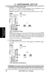
... to 66MHz, set this switch to be 2/3 of the DRAM frequency. x 2/3 DRAM Freq. ASUS P3B-F User's Manual 17 The example below shows all the switches in the OFF position. AGP Frequency ... 6 [OFF] (default) [ON] R P3B-F ON ON 1 2 3 4 5 6 7 8 9 10 1 2 3 4 5 6 7 8 9 10 DRAM Freq. HARDWARE SETUP Motherboard Feature Settings (DIP Switches-DSW) The motherboard's onboard functions are not guaranteed to [ON]. DSW ON 1. Frequency Selection 10. H/W SETUP Motherboard Settings 3. Frequency Multiple 2. Frequency Selection ON R P3B-F P3B-F DIP Switches OFF 1 2 3 4 ...
... to 66MHz, set this switch to be 2/3 of the DRAM frequency. x 2/3 DRAM Freq. ASUS P3B-F User's Manual 17 The example below shows all the switches in the OFF position. AGP Frequency ... 6 [OFF] (default) [ON] R P3B-F ON ON 1 2 3 4 5 6 7 8 9 10 1 2 3 4 5 6 7 8 9 10 DRAM Freq. HARDWARE SETUP Motherboard Feature Settings (DIP Switches-DSW) The motherboard's onboard functions are not guaranteed to [ON]. DSW ON 1. Frequency Selection 10. H/W SETUP Motherboard Settings 3. Frequency Multiple 2. Frequency Selection ON R P3B-F P3B-F DIP Switches OFF 1 2 3 4 ...

P3B-F User Manual
Page 18
...8594; 36.7MHz 1 2 3 4 5 6 7 8 9 10 112.0MHz 37.3MHz 1 2 3 4 5 6 7 8 9 10 115.0MHz 38.3MHz R P3B-F ON ON ON 1 2 3 4 5 6 7 8 9 10 CPU/DRAM → 120.0MHz PCI BUS → 40.0MHz P3B-F CPU External ON Frequency Selection 1 2 3 4 5 6 7 8 9 10 CPU/DRAM →133.0MHz PCI BUS → 33.3MHz 1 2 3 4 5 ...Motherboard Settings 3. Frequencies above 100MHz exceed the specifications for the Pentium III / II / Celeron processor because it sends VID signals directly to the CPU, DRAM, and the PCI bus. NOTE: In JumperFree mode, all dip switches (DSW) must be set to be stable. 18 ASUS P3B...
...8594; 36.7MHz 1 2 3 4 5 6 7 8 9 10 112.0MHz 37.3MHz 1 2 3 4 5 6 7 8 9 10 115.0MHz 38.3MHz R P3B-F ON ON ON 1 2 3 4 5 6 7 8 9 10 CPU/DRAM → 120.0MHz PCI BUS → 40.0MHz P3B-F CPU External ON Frequency Selection 1 2 3 4 5 6 7 8 9 10 CPU/DRAM →133.0MHz PCI BUS → 33.3MHz 1 2 3 4 5 ...Motherboard Settings 3. Frequencies above 100MHz exceed the specifications for the Pentium III / II / Celeron processor because it sends VID signals directly to the CPU, DRAM, and the PCI bus. NOTE: In JumperFree mode, all dip switches (DSW) must be set to be stable. 18 ASUS P3B...

P3B-F User Manual
Page 19
... (DSW) must be set to OFF. Set the DIP switches by the Internal speed of the CPU and the CPU's External frequency. ASUS P3B-F User's Manual 19 These must be disabled . P3B-F CPU : BUS Frequency Multiple ON ON ON 1 2 3 4 5 6 7 8 9 10 2.0x(2/1) ON 1 2 3 4 5 6 7 8 9 10 2.5x(5/2) ON 1 2 3 4 5 6 7 8 9 10 3.0x(3/1) ON 1 2 3 4 5 6 ...] [ON] [OFF][OFF] [ON] [ON] [ON] For updated processor settings, please visit ASUS' web site (see ASUS CONTACT INFORMATION). H/W SETUP Motherboard Settings Manual CPU Settings NOTE: JumperFree mode must be set in conjunction with the CPU Bus Frequency. ...
... (DSW) must be set to OFF. Set the DIP switches by the Internal speed of the CPU and the CPU's External frequency. ASUS P3B-F User's Manual 19 These must be disabled . P3B-F CPU : BUS Frequency Multiple ON ON ON 1 2 3 4 5 6 7 8 9 10 2.0x(2/1) ON 1 2 3 4 5 6 7 8 9 10 2.5x(5/2) ON 1 2 3 4 5 6 7 8 9 10 3.0x(3/1) ON 1 2 3 4 5 6 ...] [ON] [OFF][OFF] [ON] [ON] [ON] For updated processor settings, please visit ASUS' web site (see ASUS CONTACT INFORMATION). H/W SETUP Motherboard Settings Manual CPU Settings NOTE: JumperFree mode must be set in conjunction with the CPU Bus Frequency. ...
P3B-F User Manual
Page 20
Setting JEN Enable (jumperfree) [2-3] (default) Disable (jumper) [1-2] 3. H/W SETUP Motherboard Settings JEN 123 Jumper 123 JumperFree R P3B-F P3B-F Jumper Mode Setting NOTE: In JumperFree mode, your system will start up at a bus speed of your ...Setting 3.50 Volt 3.65 Volt JP20 [1-2] (default) [2-3] JP20 (VIO) 123 123 3.50 Volt (default) 3.65 Volt R P3B-F P3B-F Input/Output Voltage Setting WARNING! Leave on default setting. 20 ASUS P3B-F User's Manual NOTE: In JumperFreeTM mode, all dip switches (DSW) must be made through BIOS setup. 3. HARDWARE SETUP 4) ...
Setting JEN Enable (jumperfree) [2-3] (default) Disable (jumper) [1-2] 3. H/W SETUP Motherboard Settings JEN 123 Jumper 123 JumperFree R P3B-F P3B-F Jumper Mode Setting NOTE: In JumperFree mode, your system will start up at a bus speed of your ...Setting 3.50 Volt 3.65 Volt JP20 [1-2] (default) [2-3] JP20 (VIO) 123 123 3.50 Volt (default) 3.65 Volt R P3B-F P3B-F Input/Output Voltage Setting WARNING! Leave on default setting. 20 ASUS P3B-F User's Manual NOTE: In JumperFreeTM mode, all dip switches (DSW) must be made through BIOS setup. 3. HARDWARE SETUP 4) ...

P3B-F User Manual
Page 21
... are only available as double-sided registered memory. 3.5.1 General DIMM Notes • For the system CPU bus to ensure system stability. • ASUS motherboards support SPD (Serial Presence Detect) DIMMs. This is the memory of the DIMM takes up one row on bootup screen. • Single-sided DIMMs... 9 chips per side (standard 8 chips/side + 1 ECC chip) and make the proper settings through SDRAM Configuration in 16, 32, 64,128MB; ASUS P3B-F User's Manual 21 If your DIMMs are not PC100-compliant, set the CPU bus frequency to 66MHz RAM to operate at 100MHz, use a DIMM module...
... are only available as double-sided registered memory. 3.5.1 General DIMM Notes • For the system CPU bus to ensure system stability. • ASUS motherboards support SPD (Serial Presence Detect) DIMMs. This is the memory of the DIMM takes up one row on bootup screen. • Single-sided DIMMs... 9 chips per side (standard 8 chips/side + 1 ECC chip) and make the proper settings through SDRAM Configuration in 16, 32, 64,128MB; ASUS P3B-F User's Manual 21 If your DIMMs are not PC100-compliant, set the CPU bus frequency to 66MHz RAM to operate at 100MHz, use a DIMM module...

P3B-F User Manual
Page 22
... 3.3Volt unbuffered SDRAMs. To determine the DIMM type, check the notches on the motherboard. This motherboard supports four clock signals per DIMM. 22 ASUS P3B-F User's Manual HARDWARE SETUP 3.5.2 DIMM Memory Installation Insert the module(s) as shown. Lock 88 Pins R P3B-F P3B-F 168-Pin DIMM Memory Sockets 60 Pins 20 Pins The DIMMs must tell your...
... 3.3Volt unbuffered SDRAMs. To determine the DIMM type, check the notches on the motherboard. This motherboard supports four clock signals per DIMM. 22 ASUS P3B-F User's Manual HARDWARE SETUP 3.5.2 DIMM Memory Installation Insert the module(s) as shown. Lock 88 Pins R P3B-F P3B-F 168-Pin DIMM Memory Sockets 60 Pins 20 Pins The DIMMs must tell your...

P3B-F User Manual
Page 23
...; processor packaged in a Single Edge Processor Package (SEPP). The URM supports Pentium III / II and Celeron processors. 3. Your motherboard provides a Slot 1 connector for reference purposes only. H/W SETUP CPU Universal Retention Mechanism (URM) ASUS P3B-F User's Manual 23 Pentium II processor packaged in an SECC with heatsink and fan (top view) Pentium III (in...
...; processor packaged in a Single Edge Processor Package (SEPP). The URM supports Pentium III / II and Celeron processors. 3. Your motherboard provides a Slot 1 connector for reference purposes only. H/W SETUP CPU Universal Retention Mechanism (URM) ASUS P3B-F User's Manual 23 Pentium II processor packaged in an SECC with heatsink and fan (top view) Pentium III (in...

P3B-F User Manual
Page 24
... processor could overheat and damage both the processor and the motherboard. HARDWARE SETUP 3.6.2 Heatsinks The recommended heatsinks (see 3.6.4 Recommended Heatsinks for Slot 1 Processors for more information) for the installation of the URM are those with three-pin fans that your processor. 24 ASUS P3B-F User's Manual Be sure that there is sufficient air.... 3.6.3 Installing the Processor 1. WARNING! Locked Folding Support Arms To unlock the support arms, simply flip Unlocked Folding them up to the fan connectors on the motherboard. H/W SETUP CPU The URM is working. 3.
... processor could overheat and damage both the processor and the motherboard. HARDWARE SETUP 3.6.2 Heatsinks The recommended heatsinks (see 3.6.4 Recommended Heatsinks for Slot 1 Processors for more information) for the installation of the URM are those with three-pin fans that your processor. 24 ASUS P3B-F User's Manual Be sure that there is sufficient air.... 3.6.3 Installing the Processor 1. WARNING! Locked Folding Support Arms To unlock the support arms, simply flip Unlocked Folding them up to the fan connectors on the motherboard. H/W SETUP CPU The URM is working. 3.


