P3B-F User Manual
Page 4
...1.2 Item Checklist 7 2. HARDWARE SETUP 14 3.1 Motherboard Layout 14 3.2 Layout Contents 15 3.3 Hardware Setup Procedure 16 3.4 Motherboard Settings 16 3.5 System Memory (DIMM 21 3.5.1 General DIMM Notes 21 3.5.2 DIMM Memory Installation 22 3.6 Central Processing Unit (CPU 23 3.6.1 Universal Retention Mechanism 23 3.6.3 Installing the... System 42 4.1.2 Updating BIOS Procedures (only when necessary) ...... 43 4 ASUS P3B-F User's Manual FEATURES 8 2.1 The ASUS P3B-F Motherboard 8 2.1.1 Specifications 8 2.1.2 Special Features 10 2.1.3 Performance Features 10 2.1.4 Intelligence 11...
...1.2 Item Checklist 7 2. HARDWARE SETUP 14 3.1 Motherboard Layout 14 3.2 Layout Contents 15 3.3 Hardware Setup Procedure 16 3.4 Motherboard Settings 16 3.5 System Memory (DIMM 21 3.5.1 General DIMM Notes 21 3.5.2 DIMM Memory Installation 22 3.6 Central Processing Unit (CPU 23 3.6.1 Universal Retention Mechanism 23 3.6.3 Installing the... System 42 4.1.2 Updating BIOS Procedures (only when necessary) ...... 43 4 ASUS P3B-F User's Manual FEATURES 8 2.1 The ASUS P3B-F Motherboard 8 2.1.1 Specifications 8 2.1.2 Special Features 10 2.1.3 Performance Features 10 2.1.4 Intelligence 11...

P3B-F User Manual
Page 5
... PCI Card 97 7.2 PCI-L101 Fast Ethernet Card 109 7.3 ASUS S370 Series CPU Card 111 ASUS P3B-F User's Manual 5 SOFTWARE SETUP 75 5.1 Operating Systems 75 5.2 P3B-F Support CD 75 5.3 Intel LDCM Administrator Setup 77 5.4 Intel LDCM Client Setup 78 5.5 Install ASUS PC Probe Vx.xx 80 5.6 Install ASUS Update Vx.xx 81 5.7 Install PC-Cillin 98 Vx... 65 4.5 Power Menu 66 4.5.1 Power Up Control 68 4.5.2 Hardware Monitor 70 4.6 Boot Menu 71 4.7 Exit Menu 73 5. SOFTWARE REFERENCE 85 6.1 Intel LANDesk Client Manager 85 6.2 ASUS PC Probe 91 7.
... PCI Card 97 7.2 PCI-L101 Fast Ethernet Card 109 7.3 ASUS S370 Series CPU Card 111 ASUS P3B-F User's Manual 5 SOFTWARE SETUP 75 5.1 Operating Systems 75 5.2 P3B-F Support CD 75 5.3 Intel LDCM Administrator Setup 77 5.4 Intel LDCM Client Setup 78 5.5 Install ASUS PC Probe Vx.xx 80 5.6 Install ASUS Update Vx.xx 81 5.7 Install PC-Cillin 98 Vx... 65 4.5 Power Menu 66 4.5.1 Power Up Control 68 4.5.2 Hardware Monitor 70 4.6 Boot Menu 71 4.7 Exit Menu 73 5. SOFTWARE REFERENCE 85 6.1 Intel LANDesk Client Manager 85 6.2 ASUS PC Probe 91 7.

P3B-F User Manual
Page 7
... spare jumper caps (1) Support CD with drivers and utilities (1) This Motherboard User's Manual ASUS IrDA-compliant infrared module (optional) ASUS S370 Series CPU cards (optional) ASUS PCI-L101 Wake-On-LAN 10/100 ethernet card (optional) ASUS P3B-F User's Manual 7 Software Setup Instructions on setting up the motherboard and jumpers 4. Features Information and specifications concerning this product 3. If...
... spare jumper caps (1) Support CD with drivers and utilities (1) This Motherboard User's Manual ASUS IrDA-compliant infrared module (optional) ASUS S370 Series CPU cards (optional) ASUS PCI-L101 Wake-On-LAN 10/100 ethernet card (optional) ASUS P3B-F User's Manual 7 Software Setup Instructions on setting up the motherboard and jumpers 4. Features Information and specifications concerning this product 3. If...

P3B-F User Manual
Page 8
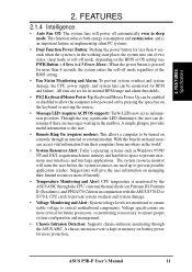
...to physically transport commands and information between SMBus devices. 8 ASUS P3B-F User's Manual FEATURES 2.1 The ASUS P3B-F Motherboard The ASUS P3B-F is carefully designed for the demanding PC user who wants advanced features processed by the fastest CPU. 2.1.1 Specifications • Multi-Speed: Supports Intel Pentium&#... with four DIMM sockets to support Intel PC100-compliant SDRAMs (8, 16, 32, 64, 128, or 256MB) up functions from ASUS. • Enhanced ACPI & Anti-Boot Virus Protection: Programmable BIOS (flash EEPROM), offering enhanced ACPI for Windows 98 compatibility, built...
...to physically transport commands and information between SMBus devices. 8 ASUS P3B-F User's Manual FEATURES 2.1 The ASUS P3B-F Motherboard The ASUS P3B-F is carefully designed for the demanding PC user who wants advanced features processed by the fastest CPU. 2.1.1 Specifications • Multi-Speed: Supports Intel Pentium&#... with four DIMM sockets to support Intel PC100-compliant SDRAMs (8, 16, 32, 64, 128, or 256MB) up functions from ASUS. • Enhanced ACPI & Anti-Boot Virus Protection: Programmable BIOS (flash EEPROM), offering enhanced ACPI for Windows 98 compatibility, built...
P3B-F User Manual
Page 11
... systems such as information providers. When the power button is pressed for future processors, so monitoring is necessary to critical motherboard components. The system resource monitor will warn the user before the system resources are set for more efficiently. • Temperature Monitoring and ...and system damage, the CPU, power supply, and system fans can determine if there are more critical for more memory and hard drive space to be enabled or disabled to allow the computer to present enormous user interfaces and run large applications. ASUS P3B-F User's Manual 11 2....
... systems such as information providers. When the power button is pressed for future processors, so monitoring is necessary to critical motherboard components. The system resource monitor will warn the user before the system resources are set for more efficiently. • Temperature Monitoring and ...and system damage, the CPU, power supply, and system fans can determine if there are more critical for more memory and hard drive space to be enabled or disabled to allow the computer to present enormous user interfaces and run large applications. ASUS P3B-F User's Manual 11 2....

P3B-F User Manual
Page 12
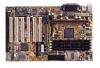
2. FEA TURES Specifications 2. FEATURES 2.2 Motherboard Parts 1 ATX Power Connector 2 Slot 1 CPU Socket 3 Intel 440BX AGPset 4 4 DIMM Sockets 5 IDE Connectors 6 ASUS ASIC with hardware monitor 7 Floppy Disk Drive Connector 8 Function DIP Switches 9 Intel PIIX4E PCIset 10 Onboard LED 11 Wake-On-Ring Connector 12 1 or 2 ISA ... Graphics Port 18 Serial Port Connector 19 Parallel Port Connector 20 Serial Port Connector 21 2 USB Connectors 22 T: PS/2 Mouse Connector B: PS/2 Keyboard Connector 12 ASUS P3B-F User's Manual
2. FEA TURES Specifications 2. FEATURES 2.2 Motherboard Parts 1 ATX Power Connector 2 Slot 1 CPU Socket 3 Intel 440BX AGPset 4 4 DIMM Sockets 5 IDE Connectors 6 ASUS ASIC with hardware monitor 7 Floppy Disk Drive Connector 8 Function DIP Switches 9 Intel PIIX4E PCIset 10 Onboard LED 11 Wake-On-Ring Connector 12 1 or 2 ISA ... Graphics Port 18 Serial Port Connector 19 Parallel Port Connector 20 Serial Port Connector 21 2 USB Connectors 22 T: PS/2 Mouse Connector B: PS/2 Keyboard Connector 12 ASUS P3B-F User's Manual

P3B-F User Manual
Page 15
HARDWARE SETUP 3.2 Layout Contents Motherboard Settings 1) DSW-Switch 6 2) DSW-Switches 7-10 3) DSW-Switches 1-4 4) JEN 5) JP20 p. 17 AGP Bus Frequency Setting p. 18 CPU External Clock (BUS) Frequency Selection p. 19 CPU Core:BUS Frequency Multiple p. 20 JumperFreeTM Mode Setting (Enable/Disable) p. 20 I/O ...(2 pins) 20) PWR.SW (PANEL) p. 37 ATX / Soft-Off Switch Lead (2 pins) 21) RESET (PANEL) p. 37 Reset Switch Lead (2 pins) 22) ATXPWR p. 38 ATX Power Supply Connector (20 pins) 23) JTPWR p. 38 Thermal Sensor Connector ASUS P3B-F User's Manual 15 3. H/W SETUP Layout Contents 3....
HARDWARE SETUP 3.2 Layout Contents Motherboard Settings 1) DSW-Switch 6 2) DSW-Switches 7-10 3) DSW-Switches 1-4 4) JEN 5) JP20 p. 17 AGP Bus Frequency Setting p. 18 CPU External Clock (BUS) Frequency Selection p. 19 CPU Core:BUS Frequency Multiple p. 20 JumperFreeTM Mode Setting (Enable/Disable) p. 20 I/O ...(2 pins) 20) PWR.SW (PANEL) p. 37 ATX / Soft-Off Switch Lead (2 pins) 21) RESET (PANEL) p. 37 Reset Switch Lead (2 pins) 22) ATXPWR p. 38 ATX Power Supply Connector (20 pins) 23) JTPWR p. 38 Thermal Sensor Connector ASUS P3B-F User's Manual 15 3. H/W SETUP Layout Contents 3....

P3B-F User Manual
Page 16
3. Install Expansion Cards 5. Install the Central Processing Unit (CPU) 4. If you do not have one, touch both of switches and/or jumpers. Connect Ribbon Cables, Panel Wires, and Power Supply 6. Unplug your ...wrist strap before handling computer components. Hold components by the edges and try not to a metal object, such as the power supply case. 3. H/W SETUP Motherboard Settings 16 ASUS P3B-F User's Manual Install Memory Modules 3. WARNING! To protect them against damage from the system. 3. HARDWARE SETUP 3.3 Hardware Setup Procedure Before using your computer,...
3. Install Expansion Cards 5. Install the Central Processing Unit (CPU) 4. If you do not have one, touch both of switches and/or jumpers. Connect Ribbon Cables, Panel Wires, and Power Supply 6. Unplug your ...wrist strap before handling computer components. Hold components by the edges and try not to a metal object, such as the power supply case. 3. H/W SETUP Motherboard Settings 16 ASUS P3B-F User's Manual Install Memory Modules 3. WARNING! To protect them against damage from the system. 3. HARDWARE SETUP 3.3 Hardware Setup Procedure Before using your computer,...

P3B-F User Manual
Page 17
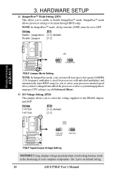
... P3B-F P3B-F DIP Switches OFF 1 2 3 4 5 6 7 8 9 10 1) AGP Bus Frequency Setting (DSW-Switch 6) This option sets the frequency ratio between the AGP bus frequency and the DRAM (CPU bus) frequency. The default sets the AGP bus frequency to [ON]. When the CPU/...are adjusted through the DIP switches. The white block represents the switch's position. AGP Frequency Selection 7. Frequency Multiple 4. ASUS P3B-F User's Manual 17 H/W SETUP Motherboard Settings 3. x 2/3 DRAM Freq. Frequency Selection 8. Frequency Selection 9. Frequency Multiple 2. x1 DRAM Freq. See the ...
... P3B-F P3B-F DIP Switches OFF 1 2 3 4 5 6 7 8 9 10 1) AGP Bus Frequency Setting (DSW-Switch 6) This option sets the frequency ratio between the AGP bus frequency and the DRAM (CPU bus) frequency. The default sets the AGP bus frequency to [ON]. When the CPU/...are adjusted through the DIP switches. The white block represents the switch's position. AGP Frequency Selection 7. Frequency Multiple 4. ASUS P3B-F User's Manual 17 H/W SETUP Motherboard Settings 3. x 2/3 DRAM Freq. Frequency Selection 8. Frequency Selection 9. Frequency Multiple 2. x1 DRAM Freq. See the ...

P3B-F User Manual
Page 18
...3MHz 1 2 3 4 5 6 7 8 9 10 115.0MHz 38.3MHz R P3B-F ON ON ON 1 2 3 4 5 6 7 8 9 10 CPU/DRAM → 120.0MHz PCI BUS → 40.0MHz P3B-F CPU External ON Frequency Selection 1 2 3 4 5 6 7 8 9 10 CPU/DRAM →133.0MHz PCI BUS → 33.3MHz 1 2 3 4 5 6...CPU's External frequency (or BUS Clock). HARDWARE SETUP 2) CPU External Frequency Selection (DSW-Switches 7-10) This option tells the clock generator what frequency to send to the onboard power controller. H/W SETUP Motherboard Settings 3. NOTE: In JumperFree mode, all dip switches (DSW) must be stable. 18 ASUS P3B...
...3MHz 1 2 3 4 5 6 7 8 9 10 115.0MHz 38.3MHz R P3B-F ON ON ON 1 2 3 4 5 6 7 8 9 10 CPU/DRAM → 120.0MHz PCI BUS → 40.0MHz P3B-F CPU External ON Frequency Selection 1 2 3 4 5 6 7 8 9 10 CPU/DRAM →133.0MHz PCI BUS → 33.3MHz 1 2 3 4 5 6...CPU's External frequency (or BUS Clock). HARDWARE SETUP 2) CPU External Frequency Selection (DSW-Switches 7-10) This option tells the clock generator what frequency to send to the onboard power controller. H/W SETUP Motherboard Settings 3. NOTE: In JumperFree mode, all dip switches (DSW) must be stable. 18 ASUS P3B...

P3B-F User Manual
Page 19
... ASUS CONTACT INFORMATION). P3B-F CPU : BUS Frequency Multiple ON ON ON 1 2 3 4 5 6 7 8 9 10 2.0x(2/1) ON 1 2 3 4 5 6 7 8 9 10 2.5x(5/2) ON 1 2 3 4 5 6 7 8 9 10 3.0x(3/1) ON 1 2 3 4 5 6 7 8 9 10 1 2 3 4 5 6 7 8 9 10 1 2 3 4 5 6 7 8 9 10 3.5x(7/2) 4.0x(4/1) 4.5x(9/2) ON ON ON 1 2 3 4 5 6 7 8 9 10 5.0x(5/1) ON 1 2 3 4 5 6 7 8 9 10 5.5x(11/2) ON 1 2 3 4 5 6 7 8 9 10 6.0x(6/1) ON 1 2 3 4 5 6 7 8 9 10 6.5x(13/2) ON 1 2 3 4 5 6 7 8 9 10 7.0x(7/1) 1 2 3 4 5 6 7 8 9 10 7.5x(15/2) 1 2 3 4 5 6 7 8 9 10 8.0x(8/1) R P3B-F 3. H/W SETUP Motherboard Settings Manual CPU...
... ASUS CONTACT INFORMATION). P3B-F CPU : BUS Frequency Multiple ON ON ON 1 2 3 4 5 6 7 8 9 10 2.0x(2/1) ON 1 2 3 4 5 6 7 8 9 10 2.5x(5/2) ON 1 2 3 4 5 6 7 8 9 10 3.0x(3/1) ON 1 2 3 4 5 6 7 8 9 10 1 2 3 4 5 6 7 8 9 10 1 2 3 4 5 6 7 8 9 10 3.5x(7/2) 4.0x(4/1) 4.5x(9/2) ON ON ON 1 2 3 4 5 6 7 8 9 10 5.0x(5/1) ON 1 2 3 4 5 6 7 8 9 10 5.5x(11/2) ON 1 2 3 4 5 6 7 8 9 10 6.0x(6/1) ON 1 2 3 4 5 6 7 8 9 10 6.5x(13/2) ON 1 2 3 4 5 6 7 8 9 10 7.0x(7/1) 1 2 3 4 5 6 7 8 9 10 7.5x(15/2) 1 2 3 4 5 6 7 8 9 10 8.0x(8/1) R P3B-F 3. H/W SETUP Motherboard Settings Manual CPU...
P3B-F User Manual
Page 20
3. H/W SETUP Motherboard Settings JEN 123 Jumper 123 JumperFree R P3B-F P3B-F Jumper Mode Setting NOTE: In JumperFree mode, your system will start up at a bus speed of your processor internal speed after you have changed/reinstalled the processor or after a system hangup due to improper CPU settings (see 4.4 Advanced Menu). 5) ...JumperFreeTM mode allows processor settings to be set to the DRAM, chipset, and AGP. Leave on default setting. 20 ASUS P3B-F User's Manual HARDWARE SETUP 4) JumperFreeTM Mode Setting (JEN) This allows you to select the voltage supplied to OFF.
3. H/W SETUP Motherboard Settings JEN 123 Jumper 123 JumperFree R P3B-F P3B-F Jumper Mode Setting NOTE: In JumperFree mode, your system will start up at a bus speed of your processor internal speed after you have changed/reinstalled the processor or after a system hangup due to improper CPU settings (see 4.4 Advanced Menu). 5) ...JumperFreeTM mode allows processor settings to be set to the DRAM, chipset, and AGP. Leave on default setting. 20 ASUS P3B-F User's Manual HARDWARE SETUP 4) JumperFreeTM Mode Setting (JEN) This allows you to select the voltage supplied to OFF.

P3B-F User Manual
Page 21
..., 256MB DIMMs are only available as double-sided registered memory. 3.5.1 General DIMM Notes • For the system CPU bus to ensure system stability. • ASUS motherboards support SPD (Serial Presence Detect) DIMMs. This is required after adding or removing memory. Memory speed setup is ... When this speed. One side (with and without ECC. • SDRAM chips are available for best performance vs. ASUS P3B-F User's Manual 21 This motherboard uses only Dual Inline Memory Modules (DIMMs). Install memory in 4.4.1 Chip Configuration. If your DIMMs are used because of...
..., 256MB DIMMs are only available as double-sided registered memory. 3.5.1 General DIMM Notes • For the system CPU bus to ensure system stability. • ASUS motherboards support SPD (Serial Presence Detect) DIMMs. This is required after adding or removing memory. Memory speed setup is ... When this speed. One side (with and without ECC. • SDRAM chips are available for best performance vs. ASUS P3B-F User's Manual 21 This motherboard uses only Dual Inline Memory Modules (DIMMs). Install memory in 4.4.1 Chip Configuration. If your DIMMs are used because of...

P3B-F User Manual
Page 23
... retention mechanism and fan may be used on any ASUS motherboard with a Universal Retention Mechanism (URM). H/W SETUP CPU Universal Retention Mechanism (URM) ASUS P3B-F User's Manual 23 Your motherboard provides a Slot 1 connector for reference purposes only. The URM supports Pentium III / II and Celeron processors. 3. An ASUS S370 CPU card can allow Socket 370 processors to SECC2 fan...
... retention mechanism and fan may be used on any ASUS motherboard with a Universal Retention Mechanism (URM). H/W SETUP CPU Universal Retention Mechanism (URM) ASUS P3B-F User's Manual 23 Your motherboard provides a Slot 1 connector for reference purposes only. The URM supports Pentium III / II and Celeron processors. 3. An ASUS S370 CPU card can allow Socket 370 processors to SECC2 fan...

P3B-F User Manual
Page 24
... processors are locked when shipped. Without sufficient circulation, the processor could overheat and damage both the processor and the motherboard. Unlock the URM's Folding Support Arms: The folding support arms of your CPU fan is sufficient air circulation across the processor's heatsink by regularly checking that can be connected to an upright... (see 3.6.4 Recommended Heatsinks for Slot 1 Processors for more information) for the installation of the URM are those with three-pin fans that your processor. 24 ASUS P3B-F User's Manual Be sure that there is working.
... processors are locked when shipped. Without sufficient circulation, the processor could overheat and damage both the processor and the motherboard. Unlock the URM's Folding Support Arms: The folding support arms of your CPU fan is sufficient air circulation across the processor's heatsink by regularly checking that can be connected to an upright... (see 3.6.4 Recommended Heatsinks for Slot 1 Processors for more information) for the installation of the URM are those with three-pin fans that your processor. 24 ASUS P3B-F User's Manual Be sure that there is working.

P3B-F User Manual
Page 25
... the ends of the SECC2. otherwise, the CPU will overheat. The following steps are provided only as a general guide and may install an auxiliary fan to the processor. Four Pins and metal clip NOTE: The SEPP heatsink and fan (for your heatsink or processor. ASUS P3B-F User's Manual 25 HARDWARE SETUP 2. Using the...
... the ends of the SECC2. otherwise, the CPU will overheat. The following steps are provided only as a general guide and may install an auxiliary fan to the processor. Four Pins and metal clip NOTE: The SEPP heatsink and fan (for your heatsink or processor. ASUS P3B-F User's Manual 25 HARDWARE SETUP 2. Using the...

P3B-F User Manual
Page 26
With the heatsink facing the motherboard's chipset, push the SECC2, SECC, or SEPP gently but firmly into the Slot 1 connector until it is fully inserted. Secure the SECC2/SECC/SEPP Secure ... in step 2 shows the locks in the outward position and inward in the picture below). H/W SETUP CPU 3. SECC SECC2/SEPP Push lock inward CPU fan cable to fan connector CPU fan cable to fan connector 26 ASUS P3B-F User's Manual Insert the SECC2/SECC/SEPP SECC with Pentium® II only: The SECC locks should...
With the heatsink facing the motherboard's chipset, push the SECC2, SECC, or SEPP gently but firmly into the Slot 1 connector until it is fully inserted. Secure the SECC2/SECC/SEPP Secure ... in step 2 shows the locks in the outward position and inward in the picture below). H/W SETUP CPU 3. SECC SECC2/SEPP Push lock inward CPU fan cable to fan connector CPU fan cable to fan connector 26 ASUS P3B-F User's Manual Insert the SECC2/SECC/SEPP SECC with Pentium® II only: The SECC locks should...

P3B-F User Manual
Page 27
...Fan NOTE: The SEPP heatsink and fan (for the Slot 1 processors are those with the Intel LANDesk Client Manager (LDCM) or the ASUS PC Probe software. These heatsinks dissipate heat more efficiently and with an optional hardware monitor, they can monitor the fan's RPM and use the... alert function with three-pin fans, such as the ASUS Smart Fan, that the clamping design is similar to the SECC2 heatsink and fan except that can be connected to the motherboard's CPU fan connector. H/W SETUP CPU ASUS P3B-F User's Manual 27 HARDWARE SETUP 3.6.4 Recommended Heatsinks for Slot 1...
...Fan NOTE: The SEPP heatsink and fan (for the Slot 1 processors are those with the Intel LANDesk Client Manager (LDCM) or the ASUS PC Probe software. These heatsinks dissipate heat more efficiently and with an optional hardware monitor, they can monitor the fan's RPM and use the... alert function with three-pin fans, such as the ASUS Smart Fan, that the clamping design is similar to the SECC2 heatsink and fan except that can be connected to the motherboard's CPU fan connector. H/W SETUP CPU ASUS P3B-F User's Manual 27 HARDWARE SETUP 3.6.4 Recommended Heatsinks for Slot 1...
P3B-F User Manual
Page 28
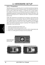
...motherboards that is reporting a CPU temperature above its maximum specified operating temperature will shorten the processor lifetime and may be continuous with a strong retention clip. 4. Included inside Pentium III, Pentium II (Deschutes), and PPGA370 Celeron processors is a thermal sensor that take readings from the processor thermal diode. H/W SETUP CPU 28 ASUS P3B...-F User's Manual Therefore, the CPU temperature reported may cause unreliable operation. 3. To prevent system ...
...motherboards that is reporting a CPU temperature above its maximum specified operating temperature will shorten the processor lifetime and may be continuous with a strong retention clip. 4. Included inside Pentium III, Pentium II (Deschutes), and PPGA370 Celeron processors is a thermal sensor that take readings from the processor thermal diode. H/W SETUP CPU 28 ASUS P3B...-F User's Manual Therefore, the CPU temperature reported may cause unreliable operation. 3. To prevent system ...

P3B-F User Manual
Page 35
...devices connected to the Primary or Secondary IDE connectors will overheat if there is to the motherboard and/or the CPU fan if these pins are not jumpers, do not place jumper caps over these pins. R P3B-F 3. Orientate the fans so that the heat sink fins allow airflow to light up. ... the polarity of 500mA (6W) or less. Read and write activity by a specially designed fan with rotation signal. Power Supply Fan CPU Fan Power Rotation +12V GND Rotation +12V GND R P3B-F Rotation +12V GND Chassis Fan Power P3B-F 12Volt Cooling Fan Power ASUS P3B-F User's Manual 35
...devices connected to the Primary or Secondary IDE connectors will overheat if there is to the motherboard and/or the CPU fan if these pins are not jumpers, do not place jumper caps over these pins. R P3B-F 3. Orientate the fans so that the heat sink fins allow airflow to light up. ... the polarity of 500mA (6W) or less. Read and write activity by a specially designed fan with rotation signal. Power Supply Fan CPU Fan Power Rotation +12V GND Rotation +12V GND R P3B-F Rotation +12V GND Chassis Fan Power P3B-F 12Volt Cooling Fan Power ASUS P3B-F User's Manual 35


