
User Manual
Page 8
... a standard protocol creating a higher level of hard drives, expansion cards, and other devices virtually automatic. • Optional PS/2 Mouse, USB, IrDA: Supports an optional cable and bracket set to mount the connectors to support an AT or ATX power supply with three DIMM sockets... either 5.25-inch (360KB or 1.2MB) or 3.5-inch (720KB, 1.44MB, or 2.88MB) disk drives. Supports two drives of the ASUS P2L-B Motherboard The ASUS P2L-B is available for high performance, component level interconnect targeted at 3D graphical display applications. • Dual Power Supply: Has both AT and ...
... a standard protocol creating a higher level of hard drives, expansion cards, and other devices virtually automatic. • Optional PS/2 Mouse, USB, IrDA: Supports an optional cable and bracket set to mount the connectors to support an AT or ATX power supply with three DIMM sockets... either 5.25-inch (360KB or 1.2MB) or 3.5-inch (720KB, 1.44MB, or 2.88MB) disk drives. Supports two drives of the ASUS P2L-B Motherboard The ASUS P2L-B is available for high performance, component level interconnect targeted at 3D graphical display applications. • Dual Power Supply: Has both AT and ...
User Manual
Page 11
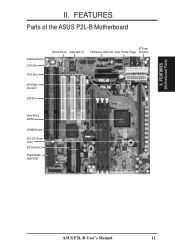
FEATURES Parts of the ASUS P2L-B Motherboard Hardware Monitor 2 ISA Slots 3 PCI Slots ATX Power Connector AGP Slot Thermal Sensor Super Multi-I/O AT Power PS/2 Mouse, USB, IrDA Serial, Parallel, Floppy Connector Intel's 440LX AGPset 3 DIMM Sockets SEC CPU Socket (Slot1) IDE Connectors Programmable Flash ROM ASUS P2L-B User's Manual 11 FEATURES (Motherboard Parts) II. II.
FEATURES Parts of the ASUS P2L-B Motherboard Hardware Monitor 2 ISA Slots 3 PCI Slots ATX Power Connector AGP Slot Thermal Sensor Super Multi-I/O AT Power PS/2 Mouse, USB, IrDA Serial, Parallel, Floppy Connector Intel's 440LX AGPset 3 DIMM Sockets SEC CPU Socket (Slot1) IDE Connectors Programmable Flash ROM ASUS P2L-B User's Manual 11 FEATURES (Motherboard Parts) II. II.
User Manual
Page 12
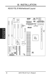
INSTALLATION (Motherboard Layout) III. INSTALLATION ASUS P2L-B Motherboard Layout ISA Slot 2 ISA Slot 1 PCI Slot 3 Hardware Monitor Thermal Sensor PCI Slot 2 Super Multi-I/O PCI Slot 1 PS/2 Mouse, USB, IrDA Parallel (Printer) Port COM 1 Key- Keyboard board Power Serial Ports AT Power Input COM 2 P9 P8 Wake on LAN Floppy Drives Power Fan ATX ... DIMM module Freq. Ratio BF0 Infrared BF1 BF2 BF3 Panel Connectors IDE LED Chassis Fan Row 5 4 3 2 1 0 FS0 FS1 FS2 Clock Freq Secondary IDE Primary IDE ASUS ASIC System BIOS Flash EEPROM 12 ASUS P2L-B User's Manual III.
INSTALLATION (Motherboard Layout) III. INSTALLATION ASUS P2L-B Motherboard Layout ISA Slot 2 ISA Slot 1 PCI Slot 3 Hardware Monitor Thermal Sensor PCI Slot 2 Super Multi-I/O PCI Slot 1 PS/2 Mouse, USB, IrDA Parallel (Printer) Port COM 1 Key- Keyboard board Power Serial Ports AT Power Input COM 2 P9 P8 Wake on LAN Floppy Drives Power Fan ATX ... DIMM module Freq. Ratio BF0 Infrared BF1 BF2 BF3 Panel Connectors IDE LED Chassis Fan Row 5 4 3 2 1 0 FS0 FS1 FS2 Clock Freq Secondary IDE Primary IDE ASUS ASIC System BIOS Flash EEPROM 12 ASUS P2L-B User's Manual III.
User Manual
Page 13
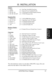
...11) PWR SW. (PANEL) 12) RESET (PANEL) 13) PWR.LED (PANEL) 14) KEYLOCK (PANEL) 15) SPEAKER (PANEL) 16) USB/MIR 17) IR 18) ATX POWER 19) AT POWER p. 26 Keyboard Connector (5-pin Female) p. 26 Floppy Drive Connector (34-1pins) ...LED Lead (3 pins) p. 30 Keyboard Lock Switch Lead (2 pins) p. 30 Speaker Output Connector (4 pins) p. 31 PS/2 Mouse/USB/IR Combo-Connector (18-1pins) p. 31 Second Infrared Port Module Connector (5-pins) p. 32 ATX Motherboard Power Connector (20-pins) p. ... use this address or else conflicts will occur. ASUS P2L-B User's Manual 13 III. INSTALLATION (Map of Board) III.
...11) PWR SW. (PANEL) 12) RESET (PANEL) 13) PWR.LED (PANEL) 14) KEYLOCK (PANEL) 15) SPEAKER (PANEL) 16) USB/MIR 17) IR 18) ATX POWER 19) AT POWER p. 26 Keyboard Connector (5-pin Female) p. 26 Floppy Drive Connector (34-1pins) ...LED Lead (3 pins) p. 30 Keyboard Lock Switch Lead (2 pins) p. 30 Speaker Output Connector (4 pins) p. 31 PS/2 Mouse/USB/IR Combo-Connector (18-1pins) p. 31 Second Infrared Port Module Connector (5-pins) p. 32 ATX Motherboard Power Connector (20-pins) p. ... use this address or else conflicts will occur. ASUS P2L-B User's Manual 13 III. INSTALLATION (Map of Board) III.
User Manual
Page 27
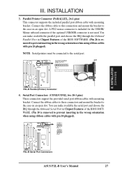
... INSTALLATION 3. NOTE: Serial printers must be connected to the case on an open slot. COM 1 Pin 1 R COM 2 Pin 1 P2L-B Serial Port Connectors ASUS P2L-B User's Manual 27 III. Serial Port Connectors (COM1/COM2, two 10-1 pins) These connectors support the provided serial port ribbon cables with...supports the included parallel port ribbon cable with mounting bracket. A PS/2 mouse connector is included for the USB/IR/ Mouse onboard connector if the optional USB/MIR connector is removed to prevent inserting in the wrong orientation when using ribbon cables with pin 10 plugged...
... INSTALLATION 3. NOTE: Serial printers must be connected to the case on an open slot. COM 1 Pin 1 R COM 2 Pin 1 P2L-B Serial Port Connectors ASUS P2L-B User's Manual 27 III. Serial Port Connectors (COM1/COM2, two 10-1 pins) These connectors support the provided serial port ribbon cables with...supports the included parallel port ribbon cable with mounting bracket. A PS/2 mouse connector is included for the USB/IR/ Mouse onboard connector if the optional USB/MIR connector is removed to prevent inserting in the wrong orientation when using ribbon cables with pin 10 plugged...
User Manual
Page 31
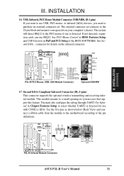
... View R (NC) GND +5V IRRX IRTX IRTX GND IRRX +5V (NC) P2L-B Infrared Module Connector ASUS P2L-B User's Manual 31 USB, Infrared, PS/2 Mouse Module Connector (USB/MIR, 18-1 pins) If you want to use USB, PS/2 mouse, or infrared (IrDA) devices, you need to the pin definitions... 15: PS/2 Mouse Data 7: Ground 16: Ground 8: (no connection) 17: Infrared Receive 9: +5 Volt 18: Infrared Transmit USB 0 USB 1 P2L-B PS/2 Mouse, USB, IrDA Module Connector Optional USB/MIR 17. connector for use IRQ12. This module mounts to the PS/2 mouse if one is directed for details on your computer...
... View R (NC) GND +5V IRRX IRTX IRTX GND IRRX +5V (NC) P2L-B Infrared Module Connector ASUS P2L-B User's Manual 31 USB, Infrared, PS/2 Mouse Module Connector (USB/MIR, 18-1 pins) If you want to use USB, PS/2 mouse, or infrared (IrDA) devices, you need to the pin definitions... 15: PS/2 Mouse Data 7: Ground 16: Ground 8: (no connection) 17: Infrared Receive 9: +5 Volt 18: Infrared Transmit USB 0 USB 1 P2L-B PS/2 Mouse, USB, IrDA Module Connector Optional USB/MIR 17. connector for use IRQ12. This module mounts to the PS/2 mouse if one is directed for details on your computer...
User Manual
Page 51
... you must set the base address and block size of No/ICU. If you have an IRQ# and therefore prevents the USB from the six available options; Available options include: No/ICU and Yes. IV. The first option, the default setting, ... the ISA MEM Block SIZE field will then appear for the USB to work, Disabled does not allow the USB to either that requires to use the onboard SCSI BIOS, choose Disabled USB IRQ (Enabled) Enabled reserves an IRQ# for selecting the block... is being used by a legacy (non-PnP) ISA card. BIOS (Plug & Play / PCI) ASUS P2L-B User's Manual 51
... you must set the base address and block size of No/ICU. If you have an IRQ# and therefore prevents the USB from the six available options; Available options include: No/ICU and Yes. IV. The first option, the default setting, ... the ISA MEM Block SIZE field will then appear for the USB to work, Disabled does not allow the USB to either that requires to use the onboard SCSI BIOS, choose Disabled USB IRQ (Enabled) Enabled reserves an IRQ# for selecting the block... is being used by a legacy (non-PnP) ISA card. BIOS (Plug & Play / PCI) ASUS P2L-B User's Manual 51


