
P2B-F User Manual
Page 1
R P2B-F Pentium® III / II / CeleronTM Motherboard USER'S MANUAL
R P2B-F Pentium® III / II / CeleronTM Motherboard USER'S MANUAL
P2B-F User Manual
Page 4
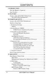
... 25 5. FEATURES 8 Features of BIOS Features Setup 41 4 ASUS P2B-F User's Manual System Memory (DIMM 17 DIMM Memory Installation Procedures 18 3. BIOS Setup 37 Load Defaults 38 Standard CMOS Setup 38 Details of Standard CMOS Setup 38 BIOS Features Setup 41 Details of the ASUS P2B-F Motherboard 8 The ASUS P2B-F Motherboard 11 III. BIOS SETUP 34 Flash Memory Writer...
... 25 5. FEATURES 8 Features of BIOS Features Setup 41 4 ASUS P2B-F User's Manual System Memory (DIMM 17 DIMM Memory Installation Procedures 18 3. BIOS Setup 37 Load Defaults 38 Standard CMOS Setup 38 Details of Standard CMOS Setup 38 BIOS Features Setup 41 Details of the ASUS P2B-F Motherboard 8 The ASUS P2B-F Motherboard 11 III. BIOS SETUP 34 Flash Memory Writer...
P2B-F User Manual
Page 7
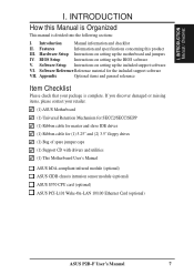
... of spare jumper caps (1) Support CD with drivers and utilities (1) This Motherboard User's Manual ASUS IrDA-compliant infrared module (optional) ASUS CIDB chassis intrusion sensor module (optional) ASUS S370 CPU card (optional) ASUS PCI-L101 Wake-On-LAN 10/100 Ethernet Card (optional) ASUS P2B-F User's Manual 7 INTRODUCTION How this product III. Hardware Setup Instructions on setting up the...
... of spare jumper caps (1) Support CD with drivers and utilities (1) This Motherboard User's Manual ASUS IrDA-compliant infrared module (optional) ASUS CIDB chassis intrusion sensor module (optional) ASUS S370 CPU card (optional) ASUS PCI-L101 Wake-On-LAN 10/100 Ethernet Card (optional) ASUS P2B-F User's Manual 7 INTRODUCTION How this product III. Hardware Setup Instructions on setting up the...
P2B-F User Manual
Page 8
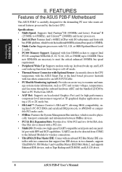
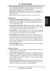
FEATURES Features of the ASUS P2B-F Motherboard The ASUS P2B-F is shared with a PCI slot. • Multi-I /O subsystems and front...-off mode. • Thermal Sensor Connector with Optional Sensor: Accurately detects the CPU temperature with the ASUS Smart Fan or the Intel boxed processor heatsink with two connectors that support four IDE devices in two ... manage system status information, such as Tape Backup and CD-ROM, and LS-120 drives. 8 ASUS P2B-F User's Manual II. FEATURES Specifications II. One ISA slot is carefully designed for high performance, component level interconnect ...
FEATURES Features of the ASUS P2B-F Motherboard The ASUS P2B-F is shared with a PCI slot. • Multi-I /O subsystems and front...-off mode. • Thermal Sensor Connector with Optional Sensor: Accurately detects the CPU temperature with the ASUS Smart Fan or the Intel boxed processor heatsink with two connectors that support four IDE devices in two ... manage system status information, such as Tape Backup and CD-ROM, and LS-120 drives. 8 ASUS P2B-F User's Manual II. FEATURES Specifications II. One ISA slot is carefully designed for high performance, component level interconnect ...
P2B-F User Manual
Page 9
.../33 IDE which can handle data transfer up to the memory and processor. • Double the IDE Transfer Speed: ASUS smart series motherboards with existing ATA-2 IDE specs so there is compatible with Intel chipsets improves IDE transfer rate using PC100-compliant SDRAM....no need to communicate within a standard protocol creating a higher level of - fering enhanced ACPI for a wireless interface. ASUS P2B-F User's Manual 9 The best of motherboards meet PC'98 compliancy. Synchronous Dynamic Random Access Memory (SDRAM) which allows hardware to upgrade current hard drives or cables....
.../33 IDE which can handle data transfer up to the memory and processor. • Double the IDE Transfer Speed: ASUS smart series motherboards with existing ATA-2 IDE specs so there is compatible with Intel chipsets improves IDE transfer rate using PC100-compliant SDRAM....no need to communicate within a standard protocol creating a higher level of - fering enhanced ACPI for a wireless interface. ASUS P2B-F User's Manual 9 The best of motherboards meet PC'98 compliancy. Synchronous Dynamic Random Access Memory (SDRAM) which allows hardware to upgrade current hard drives or cables....
P2B-F User Manual
Page 10
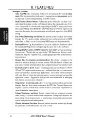
... system overheat and system damage, the CPU, power supply, and system fans can be enabled or disabled to allow the computer to critical motherboard components. The system resource monitor will power off automatically even in implementing silent PC systems. • Dual Function Power Button: Pushing the ... • Keyboard Power Up: Keyboard Power Up can be powered on by pressing the space bar on remotely through the optional ASUS CIDB module and Intel LDCM. 10 ASUS P2B-F User's Manual Suggestions will give the user information on managing their computer from anywhere in .
... system overheat and system damage, the CPU, power supply, and system fans can be enabled or disabled to allow the computer to critical motherboard components. The system resource monitor will power off automatically even in implementing silent PC systems. • Dual Function Power Button: Pushing the ... • Keyboard Power Up: Keyboard Power Up can be powered on by pressing the space bar on remotely through the optional ASUS CIDB module and Intel LDCM. 10 ASUS P2B-F User's Manual Suggestions will give the user information on managing their computer from anywhere in .
P2B-F User Manual
Page 11
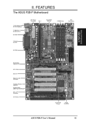
FEATURES Motherboard Parts II. FEATURES The ASUS P2B-F Motherboard T: PS/2 Mouse B: PS/2 Keyboard T: USB Conn 1 B:USB Conn 2 B:COM1 T: Parallel B:Serial ATX Power Connector Slot 1 Intel 440BX AGPset 4 DIMM Slots IDE Connectors B:COM2 Accelerated Graphics Port 5 PCI Slots Multi-I/O Wake-On-LAN Connector Hardware Monitor (optional) Programmable 2Mbit Flash EEPROM SB-Link™ Connector 2 ISA Slots Intel PIIX4E PCIset Floppy Connector ASUS P2B-F User's Manual 11 II.
FEATURES Motherboard Parts II. FEATURES The ASUS P2B-F Motherboard T: PS/2 Mouse B: PS/2 Keyboard T: USB Conn 1 B:USB Conn 2 B:COM1 T: Parallel B:Serial ATX Power Connector Slot 1 Intel 440BX AGPset 4 DIMM Slots IDE Connectors B:COM2 Accelerated Graphics Port 5 PCI Slots Multi-I/O Wake-On-LAN Connector Hardware Monitor (optional) Programmable 2Mbit Flash EEPROM SB-Link™ Connector 2 ISA Slots Intel PIIX4E PCIset Floppy Connector ASUS P2B-F User's Manual 11 II.
P2B-F User Manual
Page 12
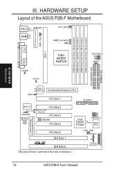
H/W SETUP Board Layout III. HARDWARE SETUP Layout of the ASUS P2B-F Motherboard PS/2 TOP: Mouse ATXPWR BOTTOM: Keyboard TOP: USB USB 1 BOTTOM: USB 2 CPU_FAN SMB Connector SMB ATX Power Connector PWR_FAN COM 1 Slot 1 Parallel Port Connector COM 2 ... Slot 1 R ISA Slot 2 (The grayed item is optional at the time of purchase.) CHA_FAN IDELED IR Infrared Connector Flash EEPROM (Programable BIOS) Panel Connectors 12 ASUS P2B-F User's Manual DIMM Socket 0 (64/72 bit, 168 pin module) DIMM Socket 1 (64/72 bit, 168 pin module) DIMM Socket 2 (64/72 bit, 168 pin module...
H/W SETUP Board Layout III. HARDWARE SETUP Layout of the ASUS P2B-F Motherboard PS/2 TOP: Mouse ATXPWR BOTTOM: Keyboard TOP: USB USB 1 BOTTOM: USB 2 CPU_FAN SMB Connector SMB ATX Power Connector PWR_FAN COM 1 Slot 1 Parallel Port Connector COM 2 ... Slot 1 R ISA Slot 2 (The grayed item is optional at the time of purchase.) CHA_FAN IDELED IR Infrared Connector Flash EEPROM (Programable BIOS) Panel Connectors 12 ASUS P2B-F User's Manual DIMM Socket 0 (64/72 bit, 168 pin module) DIMM Socket 1 (64/72 bit, 168 pin module) DIMM Socket 2 (64/72 bit, 168 pin module...

P2B-F User Manual
Page 13
III. HARDWARE SETUP Motherboard Settings 1) KBWK 2) AGPFS 3) FS0, FS1, FS2, FS3 4) BF0, BF1, BF2, BF3 p. 15 Keyboard Power Up p. 15 AGP... Connector (5 pins) 12) SBLINK p. 30 SB-Link™ Connector (6-1 pins) 13) SMB p. 30 SMBus Connector (3 pins) 14) ATXPWR p. 31 ATX Motherboard Power Connector (20 pins) 15) CHASSIS p. 31 Chassis Intrusion Alarm Lead (3 pins) 16) PWR.LED (PANEL) 17) KEYLOCK (PANEL) 18) SPEAKER (PANEL... the address 290H-297H so legacy ISA cards must not use this address otherwise conflicts will occur. ASUS P2B-F User's Manual 13 H/W SETUP Layout Contents III.
III. HARDWARE SETUP Motherboard Settings 1) KBWK 2) AGPFS 3) FS0, FS1, FS2, FS3 4) BF0, BF1, BF2, BF3 p. 15 Keyboard Power Up p. 15 AGP... Connector (5 pins) 12) SBLINK p. 30 SB-Link™ Connector (6-1 pins) 13) SMB p. 30 SMBus Connector (3 pins) 14) ATXPWR p. 31 ATX Motherboard Power Connector (20 pins) 15) CHASSIS p. 31 Chassis Intrusion Alarm Lead (3 pins) 16) PWR.LED (PANEL) 17) KEYLOCK (PANEL) 18) SPEAKER (PANEL... the address 290H-297H so legacy ISA cards must not use this address otherwise conflicts will occur. ASUS P2B-F User's Manual 13 H/W SETUP Layout Contents III.
P2B-F User Manual
Page 14
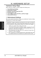
...your hands to a safely grounded object or to touch the IC chips, leads or connectors, or other components. 4. III. Check Motherboard Settings 2. Install Expansion Cards 5. Hold components by the edges and try not to a metal object, such as the power supply .../or jumpers. WARNING! Use a grounded wrist strap before handling computer components. Computer motherboards and expansion cards contain very delicate Integrated Circuit (IC) chips. H/W SETUP Motherboard Settings 14 ASUS P2B-F User's Manual If you work on the inside. 2. Install the Central Processing Unit (CPU) ...
...your hands to a safely grounded object or to touch the IC chips, leads or connectors, or other components. 4. III. Check Motherboard Settings 2. Install Expansion Cards 5. Hold components by the edges and try not to a metal object, such as the power supply .../or jumpers. WARNING! Use a grounded wrist strap before handling computer components. Computer motherboards and expansion cards contain very delicate Integrated Circuit (IC) chips. H/W SETUP Motherboard Settings 14 ASUS P2B-F User's Manual If you work on the inside. 2. Install the Central Processing Unit (CPU) ...
P2B-F User Manual
Page 15
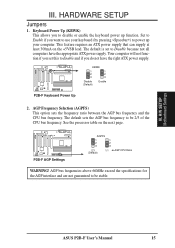
The default sets the AGP bus frequency to be stable. ASUS P2B-F User's Manual 15 Set to Enable if you want to be 2/3 of the CPU bus frequency. HARDWARE SETUP Jumpers...the specifications for the AGP interface and are not guaranteed to use your computer. KBWK 1 1 2 2 3 3 Disable (Default) Enable P2B-F Keyboard Power Up 2. AGP Frequency Selection (AGPFS) This option sets the frequency ratio between the AGP bus frequency and the CPU bus ...ATX power supply. Your computer will not function if you set to power up function. H/W SETUP Motherboard Settings III.
The default sets the AGP bus frequency to be stable. ASUS P2B-F User's Manual 15 Set to Enable if you want to be 2/3 of the CPU bus frequency. HARDWARE SETUP Jumpers...the specifications for the AGP interface and are not guaranteed to use your computer. KBWK 1 1 2 2 3 3 Disable (Default) Enable P2B-F Keyboard Power Up 2. AGP Frequency Selection (AGPFS) This option sets the frequency ratio between the AGP bus frequency and the CPU bus ...ATX power supply. Your computer will not function if you set to power up function. H/W SETUP Motherboard Settings III.
P2B-F User Manual
Page 17
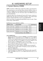
...thinner with 9 chips per side (standard 8 chips/side + 1 ECC chip) and make the proper settings through SDRAM Configuration under this motherboard operates at 100MHz, most system will not even boot if non-compliant modules are not PC100-compliant, set the CPU bus frequency to 66MHz ... the system CPU bus to ensure system stability. • ASUS motherboards support SPD (Serial Presence Detect) DIMMs. This is the memory of choice for 3.3Volt (power level) unbuffered Synchronous Dynamic Random Access Memory (SDRAM). ASUS P2B-F User's Manual 17 III. If your DIMMs are used because of the ...
...thinner with 9 chips per side (standard 8 chips/side + 1 ECC chip) and make the proper settings through SDRAM Configuration under this motherboard operates at 100MHz, most system will not even boot if non-compliant modules are not PC100-compliant, set the CPU bus frequency to 66MHz ... the system CPU bus to ensure system stability. • ASUS motherboards support SPD (Serial Presence Detect) DIMMs. This is the memory of choice for 3.3Volt (power level) unbuffered Synchronous Dynamic Random Access Memory (SDRAM). ASUS P2B-F User's Manual 17 III. If your DIMMs are used because of the ...
P2B-F User Manual
Page 18
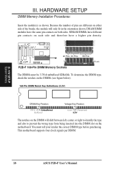
H/W SETUP System Memory III. This motherboard supports four clock signals per DIMM. 18 ASUS P2B-F User's Manual Because the number of pins are ...different on either side of the breaks, the module will shift between left, center, or right to identify the type and also to prevent the wrong type from being inserted into the DIMM slot on the motherboard...sides. DRAM SIMM modules have a higher pin density. 20 Pins 60 Pins 88 Pins Lock P2B-F 168-Pin DIMM Memory Sockets The DIMMs must tell your retailer the correct DIMM type before ...
H/W SETUP System Memory III. This motherboard supports four clock signals per DIMM. 18 ASUS P2B-F User's Manual Because the number of pins are ...different on either side of the breaks, the module will shift between left, center, or right to identify the type and also to prevent the wrong type from being inserted into the DIMM slot on the motherboard...sides. DRAM SIMM modules have a higher pin density. 20 Pins 60 Pins 88 Pins Lock P2B-F 168-Pin DIMM Memory Sockets The DIMMs must tell your retailer the correct DIMM type before ...
P2B-F User Manual
Page 19
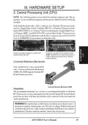
...ASUS P2B-F User's Manual 19 Central Processing Unit (CPU) NOTE: The following examples. You may be connected to SECC2 fan except that your retention mechanism and fan may install an auxiliary chassis fan, if necessary. An ASUS S370 CPU card can allow Socket 370 processors to be used on the motherboard...The appearance of your CPU fan is similar to the fan connectors on any ASUS motherboard with three-pin fans that can be different from the following pictures are those with the Slot 1 connector (See ASUS S370 CPU Card in an SECC2) with a Universal Retention Mechanism (URM). ...
...ASUS P2B-F User's Manual 19 Central Processing Unit (CPU) NOTE: The following examples. You may be connected to SECC2 fan except that your retention mechanism and fan may install an auxiliary chassis fan, if necessary. An ASUS S370 CPU card can allow Socket 370 processors to be used on the motherboard...The appearance of your CPU fan is similar to the fan connectors on any ASUS motherboard with three-pin fans that can be different from the following pictures are those with the Slot 1 connector (See ASUS S370 CPU Card in an SECC2) with a Universal Retention Mechanism (URM). ...
P2B-F User Manual
Page 21
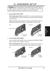
otherwise, the CPU will overheat. SECC SECC2/SEPP Push lock inward CPU fan cable to fan connector CPU fan cable to fan connector ASUS P2B-F User's Manual 21 Secure the SECC/SECC2/SEPP Secure the SECC/SECC2/SEPP in place by pushing the SECC/SECC2/SEPP until you hear a click (the picture... only: The SECC locks should be outward when secured so that the lock shows through the retention mechanism's lock holes. With the heatsink facing the motherboard's chipset, push the SECC, SECC2, or SEPP gently but firmly into the Slot 1 connector until it is mounted tightly against the SECC, SECC2 or...
otherwise, the CPU will overheat. SECC SECC2/SEPP Push lock inward CPU fan cable to fan connector CPU fan cable to fan connector ASUS P2B-F User's Manual 21 Secure the SECC/SECC2/SEPP Secure the SECC/SECC2/SEPP in place by pushing the SECC/SECC2/SEPP until you hear a click (the picture... only: The SECC locks should be outward when secured so that the lock shows through the retention mechanism's lock holes. With the heatsink facing the motherboard's chipset, push the SECC, SECC2, or SEPP gently but firmly into the Slot 1 connector until it is mounted tightly against the SECC, SECC2 or...
P2B-F User Manual
Page 22
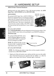
...-Cable can only be used in an SEPP. Tab Sensor ← OR STICK ABOUT HERE 22 ASUS P2B-F User's Manual ASUS S-P2FAN The optional ASUS Smart Fan or ASUS S-P2FAN is optimized by ASUS to give the most accurate reading of the CPU temperature, thus provides the best protection to your ...CPU thermal solutions, the ASUS S-P2FAN has an integrated thermal sensor located near the middle edge of the Intel boxed processor heatsink with a rock arm design for the relevant procedures. aged in an SECC2/SECC or a Celeron™ Sensor processor packaged in a Slot 1 motherboard with a 2-pin thermal...
...-Cable can only be used in an SEPP. Tab Sensor ← OR STICK ABOUT HERE 22 ASUS P2B-F User's Manual ASUS S-P2FAN The optional ASUS Smart Fan or ASUS S-P2FAN is optimized by ASUS to give the most accurate reading of the CPU temperature, thus provides the best protection to your ...CPU thermal solutions, the ASUS S-P2FAN has an integrated thermal sensor located near the middle edge of the Intel boxed processor heatsink with a rock arm design for the relevant procedures. aged in an SECC2/SECC or a Celeron™ Sensor processor packaged in a Slot 1 motherboard with a 2-pin thermal...
P2B-F User Manual
Page 23
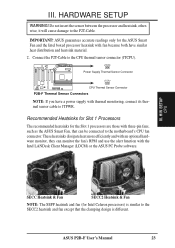
...can be connected to JTPWR. Connect the P2T-Cable to the P2T-Cable. ASUS P2B-F User's Manual 23 R III. JTPWR Power Supply Thermal Sensor Connector JTCPU CPU Thermal Sensor Connector P2B-F Thermal Sensor Connectors NOTE: If you have similar heat distribution and heatsink ...material. 2. H/W SETUP CPU SECC Heatsink & Fan SECC2 Heatsink & Fan NOTE: The SEPP heatsink and fan (for the Slot 1 processors are those with thermal monitoring, connect its thermal sensor cable to the motherboard...
...can be connected to JTPWR. Connect the P2T-Cable to the P2T-Cable. ASUS P2B-F User's Manual 23 R III. JTPWR Power Supply Thermal Sensor Connector JTCPU CPU Thermal Sensor Connector P2B-F Thermal Sensor Connectors NOTE: If you have similar heat distribution and heatsink ...material. 2. H/W SETUP CPU SECC Heatsink & Fan SECC2 Heatsink & Fan NOTE: The SEPP heatsink and fan (for the Slot 1 processors are those with thermal monitoring, connect its thermal sensor cable to the motherboard...
P2B-F User Manual
Page 24
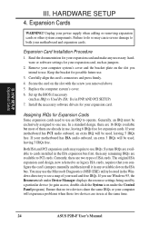
... use Windows 95, the Resources tab under the Control Panel program). System IRQs are available to use . HARDWARE SETUP 4. If your motherboard has ISA audio onboard, an extra 3 IRQs will experience problems when those two devices are two types of your expansion card and make... for your used by a particular device (to see a map of ISA cards. Currently, there are in use at the same time. 24 ASUS P2B-F User's Manual If you removed above. 5. Carefully align the card's connectors and press firmly. 4. Read the documentation for expansion cards. Set up the BIOS if...
... use Windows 95, the Resources tab under the Control Panel program). System IRQs are available to use . HARDWARE SETUP 4. If your motherboard has ISA audio onboard, an extra 3 IRQs will experience problems when those two devices are two types of your expansion card and make... for your used by a particular device (to see a map of ISA cards. Currently, there are in use at the same time. 24 ASUS P2B-F User's Manual If you removed above. 5. Carefully align the card's connectors and press firmly. 4. Read the documentation for expansion cards. Set up the BIOS if...
P2B-F User Manual
Page 25
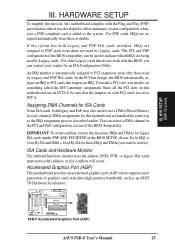
... contact your PCI cards are assigned to the system. You can be sure that the jumpers on this motherboard are being used by Legacy and PNP ISA cards. R P2B-F Accelerated Graphics Port (AGP) ASUS P2B-F User's Manual 25 If the system has both legacy and PnP, may also need to set to support a new generation...
... contact your PCI cards are assigned to the system. You can be sure that the jumpers on this motherboard are being used by Legacy and PNP ISA cards. R P2B-F Accelerated Graphics Port (AGP) ASUS P2B-F User's Manual 25 If the system has both legacy and PnP, may also need to set to support a new generation...
P2B-F User Manual
Page 26
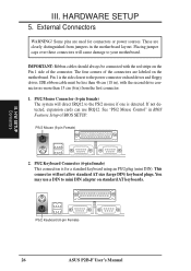
...This connection is the side closest to mini DIN adapter on the Pin 1 side of the connector. This connector will direct IRQ12 to your motherboard. Pin 1 is for connectors or power sources. PS/2 Mouse (6-pin Female) 2. You may use IRQ12. These are clearly distinguished from...III. External Connectors WARNING! The four corners of BIOS SETUP. H/W SETUP Connectors PS/2 Keyboard (6-pin Female) 26 ASUS P2B-F User's Manual See "PS/2 Mouse Control" in the motherboard layout. III. Placing jumper caps over these connectors will cause damage to the PS/2 mouse if one is detected...
...This connection is the side closest to mini DIN adapter on the Pin 1 side of the connector. This connector will direct IRQ12 to your motherboard. Pin 1 is for connectors or power sources. PS/2 Mouse (6-pin Female) 2. You may use IRQ12. These are clearly distinguished from...III. External Connectors WARNING! The four corners of BIOS SETUP. H/W SETUP Connectors PS/2 Keyboard (6-pin Female) 26 ASUS P2B-F User's Manual See "PS/2 Mouse Control" in the motherboard layout. III. Placing jumper caps over these connectors will cause damage to the PS/2 mouse if one is detected...


