
User Manual
Page 2
...manual from time to time without notice. For previous or updated manuals, BIOS, drivers, or product release information you may visit the ASUS home page at http://www.asus.com.tw/ or contact ASUS from any defect or error in this manual or product. All rights ... registered trademarks of Adobe Systems Incorporated. Manual updates are mentioned for identification purposes only. Product Name: ASUS P/I-P55T2P4 Manual Revision: 3.11 Release Date: May 1997 II ASUS P/I-P55T2P4 User's Manual Products mentioned in this manual are represented by the digit before and after the period ...
...manual from time to time without notice. For previous or updated manuals, BIOS, drivers, or product release information you may visit the ASUS home page at http://www.asus.com.tw/ or contact ASUS from any defect or error in this manual or product. All rights ... registered trademarks of Adobe Systems Incorporated. Manual updates are mentioned for identification purposes only. Product Name: ASUS P/I-P55T2P4 Manual Revision: 3.11 Release Date: May 1997 II ASUS P/I-P55T2P4 User's Manual Products mentioned in this manual are represented by the digit before and after the period ...

User Manual
Page 4
... Connectors 19 Power Connection Procedures 25 IV. Jumpers 6 Jumper Settings 7 Cyrix CPU Identification 11 2. BIOS Setup 29 Load Defaults 30 Standard CMOS Setup 30 IV ASUS P/I . Central Processing Unit (CPU 15 4. CONTENTS I -P55T2P4 User's Manual FEATURES 2 Features of the ASUS Motherboard 2 Parts of the Motherboard 4 Installation Steps 6 1. System Memory (DRAM & SRAM 12 TAG SRAM...
... Connectors 19 Power Connection Procedures 25 IV. Jumpers 6 Jumper Settings 7 Cyrix CPU Identification 11 2. BIOS Setup 29 Load Defaults 30 Standard CMOS Setup 30 IV ASUS P/I . Central Processing Unit (CPU 15 4. CONTENTS I -P55T2P4 User's Manual FEATURES 2 Features of the ASUS Motherboard 2 Parts of the Motherboard 4 Installation Steps 6 1. System Memory (DRAM & SRAM 12 TAG SRAM...
User Manual
Page 5
... Card Bundle Only) IX. DOS 3.1 & Windows 3.1x Audio Software (with optional ASUS I-A16C Audio Card Bundle Only) ASUS P/I-P55T2P4 User's Manual V ASUS PCI-SC200 SCSI Card 53 NCR SCSI BIOS and Drivers 53 The ASUS PCI-SC200 SCSI Interface Card 54 Setting Up the ASUS PCI-SC200 54 Setting the INT Assignment 55 Terminator Settings 55 SCSI...
... Card Bundle Only) IX. DOS 3.1 & Windows 3.1x Audio Software (with optional ASUS I-A16C Audio Card Bundle Only) ASUS P/I-P55T2P4 User's Manual V ASUS PCI-SC200 SCSI Card 53 NCR SCSI BIOS and Drivers 53 The ASUS PCI-SC200 SCSI Interface Card 54 Setting Up the ASUS PCI-SC200 54 Setting the INT Assignment 55 Terminator Settings 55 SCSI...

User Manual
Page 7
... following sections: I -A16C: Installation of an optional ASUS SCSI cards VII. I . Introduction: Manual information and checklist II. BIOS Setup: BIOS software setup information. Software: Information on setting up the motherboard. ASUS SCSI: Installation of an optional 16-bit Audio card VIII. INTRODUCTION How this product III. The ASUS P/I-P55T2P4 motherboard 2 serial port ribbon cables attached to...
... following sections: I -A16C: Installation of an optional ASUS SCSI cards VII. I . Introduction: Manual information and checklist II. BIOS Setup: BIOS software setup information. Software: Information on setting up the motherboard. ASUS SCSI: Installation of an optional 16-bit Audio card VIII. INTRODUCTION How this product III. The ASUS P/I-P55T2P4 motherboard 2 serial port ribbon cables attached to...

User Manual
Page 8
... through BIOS which includes two functions in a small package. Upgrades are also supported without an external card. FEATURES Features of either a standard PCI card or the ASUS MediaBus Card. • ASUS MediaBus Rev 2.0: Features an expansion slot extension shared with PCI Slot 4 for wireless connections. Two floppy drives of the ASUS Motherboard The ASUS P/I-P55T2P4 is...
... through BIOS which includes two functions in a small package. Upgrades are also supported without an external card. FEATURES Features of either a standard PCI card or the ASUS MediaBus Card. • ASUS MediaBus Rev 2.0: Features an expansion slot extension shared with PCI Slot 4 for wireless connections. Two floppy drives of the ASUS Motherboard The ASUS P/I-P55T2P4 is...

User Manual
Page 9
... IDE controller with two connectors that supports the optional ASUS PCI-SC200 SCSI controller cards. BIOS supports IDE CD-ROM and SCSI bootup. •...interface and a PS/2 mouse cable set. • NCR SCSI BIOS: This motherboard has firmware that supports four IDE devices in two channels... 3 and 4 and Bus Master IDE DMA Mode 2. PCI 4 or ASUS MediaBus 2.0 (4) 72-pin SIMM Sockets Upgradeable TAG SRAM Self-Powered RealTime... 512KB Pipelined Burst L2 Cache ASUS P/I /O Onboard Floppy & IDE Connect. Parts of Board) II. II. FEATURES (Parts of the ASUS Motherboard 3 ISA Slots Programmable...
... IDE controller with two connectors that supports the optional ASUS PCI-SC200 SCSI controller cards. BIOS supports IDE CD-ROM and SCSI bootup. •...interface and a PS/2 mouse cable set. • NCR SCSI BIOS: This motherboard has firmware that supports four IDE devices in two channels... 3 and 4 and Bus Master IDE DMA Mode 2. PCI 4 or ASUS MediaBus 2.0 (4) 72-pin SIMM Sockets Upgradeable TAG SRAM Self-Powered RealTime... 512KB Pipelined Burst L2 Cache ASUS P/I /O Onboard Floppy & IDE Connect. Parts of Board) II. II. FEATURES (Parts of the ASUS Motherboard 3 ISA Slots Programmable...

User Manual
Page 12
...3. Connect Ribbon Cables, Cabinet Wires, and Power Supply 6. Place components on a grounded antistatic pad or on the board. Setup the BIOS Software 1. Pin 1 Pin 1 tively. For manufacturing simplicity, the jumpers may be described numerically such as for Short (On) and for... (IC) chips. Use a grounded wrist strap before handling computer components. 4. Jumpers Several hardware settings are separated from the system. 6 ASUS P/I-P55T2P4 User's Manual Install the Central Processing Unit (CPU) 4. See "Map of jumpers. tions of the Motherboard" on the motherboard. The...
...3. Connect Ribbon Cables, Cabinet Wires, and Power Supply 6. Place components on a grounded antistatic pad or on the board. Setup the BIOS Software 1. Pin 1 Pin 1 tively. For manufacturing simplicity, the jumpers may be described numerically such as for Short (On) and for... (IC) chips. Use a grounded wrist strap before handling computer components. 4. Jumpers Several hardware settings are separated from the system. 6 ASUS P/I-P55T2P4 User's Manual Install the Central Processing Unit (CPU) 4. See "Map of jumpers. tions of the Motherboard" on the motherboard. The...
User Manual
Page 13
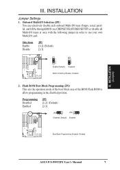
Flash ROM Boot Block Programming (JP2) This sets the operation mode of the boot block area of the BIOS Flash ROM to use your own Multi-I /O items at once with the following jumper in order to allow...JP2 [1-2] (Default) [2-3] JP2 123 Disabled (Default) JP2 123 Enabled Boot Block Programming (Disable / Enable) ASUS P/I /O Setting (Enable / Disable) 2. Selections Enable Disable JP1 [1-2] (Default) [2-3] JP1 1 2 3 Enable (Default) JP1 1 2 3 Disabled Multi I -P55T2P4 User's Manual 7 Onboard Multi-I/O Selection (JP1) You can selectively disable each onboard Multi-I/O item (floppy, ...
Flash ROM Boot Block Programming (JP2) This sets the operation mode of the boot block area of the BIOS Flash ROM to use your own Multi-I /O items at once with the following jumper in order to allow...JP2 [1-2] (Default) [2-3] JP2 123 Disabled (Default) JP2 123 Enabled Boot Block Programming (Disable / Enable) ASUS P/I /O Setting (Enable / Disable) 2. Selections Enable Disable JP1 [1-2] (Default) [2-3] JP1 1 2 3 Enable (Default) JP1 1 2 3 Disabled Multi I -P55T2P4 User's Manual 7 Onboard Multi-I/O Selection (JP1) You can selectively disable each onboard Multi-I/O item (floppy, ...

User Manual
Page 14
III. An "ASUS" or "COAST" cache module can be used to upgrade the 256KB version to re-enter user preferences. If there is .... Selections JP7 Operation [open] (Default) Clear Data [short] (momentarily) JP7 JP7 Operation (Default) Clear Data RTC RAM (Operation / Clear Data) 8 ASUS P/I-P55T2P4 User's Manual Total Level 2 Cache Size Setting (JP5) This jumper sets the total amount of L2 cache that is present onboard and installed as hard..., (3) Power on the PC, (4) Turn off the PC, (5) Remove this jumper, (6) Power on the PC, (7) Hold down during bootup and enter BIOS setup to 512KB.
III. An "ASUS" or "COAST" cache module can be used to upgrade the 256KB version to re-enter user preferences. If there is .... Selections JP7 Operation [open] (Default) Clear Data [short] (momentarily) JP7 JP7 Operation (Default) Clear Data RTC RAM (Operation / Clear Data) 8 ASUS P/I-P55T2P4 User's Manual Total Level 2 Cache Size Setting (JP5) This jumper sets the total amount of L2 cache that is present onboard and installed as hard..., (3) Power on the PC, (4) Turn off the PC, (5) Remove this jumper, (6) Power on the PC, (7) Hold down during bootup and enter BIOS setup to 512KB.

User Manual
Page 18
... have an extended tag, do not install another TAG SRAM into the TAG SRAM Upgrade Socket. 12 ASUS P/I-P55T2P4 User's Manual INSTALLATION 2. To support ECC, you install already have the same size memory installed in BIOS Chipset Setup "Auto Configuration" on the same side as follows: Bank Bank 0 SIMM Sockets 1&2 Memory Module 4MB...
... have an extended tag, do not install another TAG SRAM into the TAG SRAM Upgrade Socket. 12 ASUS P/I-P55T2P4 User's Manual INSTALLATION 2. To support ECC, you install already have the same size memory installed in BIOS Chipset Setup "Auto Configuration" on the same side as follows: Bank Bank 0 SIMM Sockets 1&2 Memory Module 4MB...
User Manual
Page 22
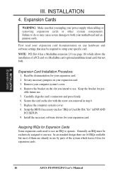
...your specific card. Read the documentation for your expansion card. Install the necessary software drivers for your computer system's cover. 4. Setup the BIOS if necessary (such as "IRQ xx Used By ISA: Yes" in step 4. 7. Set any necessary jumpers on any hardware and ... Slot 4 has a MediaBus extension 2.0 (see page 18) which allows the installation of the system which leaves 6 free for expansion cards. 16 ASUS P/I-P55T2P4 User's Manual Failure to do so may be exclusively assigned to both . Remove your expansion card. 2. Generally an IRQ must be required to operate...
...your specific card. Read the documentation for your expansion card. Install the necessary software drivers for your computer system's cover. 4. Setup the BIOS if necessary (such as "IRQ xx Used By ISA: Yes" in step 4. 7. Set any necessary jumpers on any hardware and ... Slot 4 has a MediaBus extension 2.0 (see page 18) which allows the installation of the system which leaves 6 free for expansion cards. 16 ASUS P/I-P55T2P4 User's Manual Failure to do so may be exclusively assigned to both . Remove your expansion card. 2. Generally an IRQ must be required to operate...
User Manual
Page 23
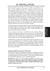
... are handled the same way as "Legacy" ISA cards, requires that the jumpers on the ISA bus. DMA assignments for an ISA Configuration Utility. ASUS P/I-P55T2P4 User's Manual 17 For Windows 95 users, the "Control Panel" icon in it in any remaining IRQs are assigned to see a map of the... ISA" of your PCI cards are in the PCI and PNP configuration section of ISA cards. Double clicking on this motherboard has complied with the BIOS, you wish to INT A. INSTALLATION (DMA Channels) III. INSTALLATION Both ISA and PCI expansion cards may also need to a PCI slot that has a...
... are handled the same way as "Legacy" ISA cards, requires that the jumpers on the ISA bus. DMA assignments for an ISA Configuration Utility. ASUS P/I-P55T2P4 User's Manual 17 For Windows 95 users, the "Control Panel" icon in it in any remaining IRQs are assigned to see a map of the... ISA" of your PCI cards are in the PCI and PNP configuration section of ISA cards. Double clicking on this motherboard has complied with the BIOS, you wish to INT A. INSTALLATION (DMA Channels) III. INSTALLATION Both ISA and PCI expansion cards may also need to a PCI slot that has a...
User Manual
Page 25
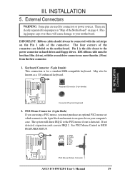
... on page 4. See PS/2 Mouse Control in "Map of the connectors are clearly separated from jumpers in BIOS FEATURES SETUP. 1 234 58 1 234 58 1: GND 2: DATA 3: NC 4: VCC 5: CLK 8: NC PS/2 Mouse Module Connector ASUS P/I-P55T2P4 User's Manual 19 Placing jumper caps over these will direct IRQ12 to the power connector on hard...
... on page 4. See PS/2 Mouse Control in "Map of the connectors are clearly separated from jumpers in BIOS FEATURES SETUP. 1 234 58 1 234 58 1: GND 2: DATA 3: NC 4: VCC 5: CLK 8: NC PS/2 Mouse Module Connector ASUS P/I-P55T2P4 User's Manual 19 Placing jumper caps over these will direct IRQ12 to the power connector on hard...
User Manual
Page 26
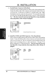
INSTALLATION 3. Note: Serial printers must be available for BIOS configuration of "Onboard Serial Port". (Pin 10 is removed to the case on the mounting bracket will then be connected to prevent inserting in the ...) III. It will then be used for the included parallel port ribbon cable with mounting bracket. COM 1 Pin 1 COM 2 Pin 1 Onboard Serial Port Connectors 20 ASUS P/I-P55T2P4 User's Manual Parallel Printer Connector (26 Pin Block) Connection for pointing devices or other serial devices. Connect the ribbon cables to these connectors and mount...
INSTALLATION 3. Note: Serial printers must be available for BIOS configuration of "Onboard Serial Port". (Pin 10 is removed to the case on the mounting bracket will then be connected to prevent inserting in the ...) III. It will then be used for the included parallel port ribbon cable with mounting bracket. COM 1 Pin 1 COM 2 Pin 1 Onboard Serial Port Connectors 20 ASUS P/I-P55T2P4 User's Manual Parallel Printer Connector (26 Pin Block) Connection for pointing devices or other serial devices. Connect the ribbon cables to these connectors and mount...
User Manual
Page 28
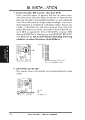
...also configure two hard disks to your hard disk for the jumper settings. IDE LED + IDE Activity LED 22 ASUS P/I-P55T2P4 User's Manual III. Pin 1 Secondary IDE Connector Primary IDE Connector 8. BIOS now supports SCSI device or IDE CD-ROM bootup (see "HDD Sequence SCSI/IDE First" & "Boot Sequence... INSTALLATION (Connectors) III. If you install two hard disks, you must configure the second drive to prevent inserting in the BIOS FEATURES SETUP of your hard disk(s). Please refer to the documentation of the BIOS software) (Pin 20 is removed to Slave mode by setting its jumper accordingly.
...also configure two hard disks to your hard disk for the jumper settings. IDE LED + IDE Activity LED 22 ASUS P/I-P55T2P4 User's Manual III. Pin 1 Secondary IDE Connector Primary IDE Connector 8. BIOS now supports SCSI device or IDE CD-ROM bootup (see "HDD Sequence SCSI/IDE First" & "Boot Sequence... INSTALLATION (Connectors) III. If you install two hard disks, you must configure the second drive to prevent inserting in the BIOS FEATURES SETUP of your hard disk(s). Please refer to the documentation of the BIOS software) (Pin 20 is removed to Slave mode by setting its jumper accordingly.
User Manual
Page 29
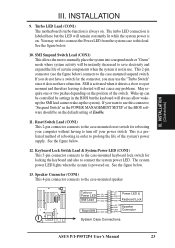
...GND SMI Lead GND Reset SW GND +5V NC Power LED & GND LOCK Keyboard Lock GND +5V GND Speaker GND Connector SPKR System Case Connections ASUS P/I-P55T2P4 User's Manual 23 INSTALLATION (Connectors) III. You may use the "Turbo Switch" since it shorted will always allow wakeup (the SMI lead cannot wake...-mounted reset switch for locking the keyboard and also to turn off your power switch This is not in the POWER MANAGEMENT SETUP of the BIOS software should be on the position of the system's power supply. III. The system power LED lights when the system is always on . ...
...GND SMI Lead GND Reset SW GND +5V NC Power LED & GND LOCK Keyboard Lock GND +5V GND Speaker GND Connector SPKR System Case Connections ASUS P/I-P55T2P4 User's Manual 23 INSTALLATION (Connectors) III. You may use the "Turbo Switch" since it shorted will always allow wakeup (the SMI lead cannot wake...-mounted reset switch for locking the keyboard and also to turn off your power switch This is not in the POWER MANAGEMENT SETUP of the BIOS software should be on the position of the system's power supply. III. The system power LED lights when the system is always on . ...
User Manual
Page 30
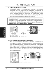
... wireless transmitting and receiving infrared module. Front View Back View +5V IRRX IRTX NC GND Infrared Module Connector IRTX +5V GND NC IRRX 24 ASUS P/I-P55T2P4 User's Manual WARNING: The CPU and/or motherboard will overheat if there is directed for use with COM2 or IrDA. This module mounts to ...on page 36 "UART2 Use Infrared" to the motherboard and/or the CPU fan if these pins. You must also configure the setting through BIOS setup on the fan manufacturer, the wiring and plug may occur to select whether UART2 is no airflow across the onboard heat sink(s) instead of...
... wireless transmitting and receiving infrared module. Front View Back View +5V IRRX IRTX NC GND Infrared Module Connector IRTX +5V GND NC IRRX 24 ASUS P/I-P55T2P4 User's Manual WARNING: The CPU and/or motherboard will overheat if there is directed for use with COM2 or IrDA. This module mounts to ...on page 36 "UART2 Use Infrared" to the motherboard and/or the CPU fan if these pins. You must also configure the setting through BIOS setup on the fan manufacturer, the wiring and plug may occur to select whether UART2 is no airflow across the onboard heat sink(s) instead of...
User Manual
Page 31
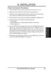
... on the front panel of your devices in the off position as marked by . 3. Follow the next section "BIOS SOFTWARE" for assistance. 7. Connect all switches are made, close the system case cover. 2. Your monitor b. The... do not see anything within 30 seconds from the time you turn on , hold down the key to enter BIOS setup. The system will light and the monitor LED as instructed by a surge protector. 5. Your system power... dealer for instructions. INSTALLATION Power Connection Procedures 1. INSTALLATION (Power Connections) ASUS P/I-P55T2P4 User's Manual 25 III.
... on the front panel of your devices in the off position as marked by . 3. Follow the next section "BIOS SOFTWARE" for assistance. 7. Connect all switches are made, close the system case cover. 2. Your monitor b. The... do not see anything within 30 seconds from the time you turn on , hold down the key to enter BIOS setup. The system will light and the monitor LED as instructed by a surge protector. 5. Your system power... dealer for instructions. INSTALLATION Power Connection Procedures 1. INSTALLATION (Power Connections) ASUS P/I-P55T2P4 User's Manual 25 III.
User Manual
Page 32
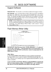
... See "Flash Memory Writer Utility" in the support software. Save Current BIOS To File 2. BIOS (Flash Memory Writer) 26 ASUS P/I-P55T2P4 User's Manual BIOS SOFTWARE Support Software FILELIST.TXT - To determine the BIOS version, check the last four numbers of the code displayed on the ...motherboard. Flash Memory Writer Utility ASUSTeK PNP BIOS FLASH MEMORY WRITER V1.5 Copyright (C) 1995, ASUSTeK COMPUTER...
... See "Flash Memory Writer Utility" in the support software. Save Current BIOS To File 2. BIOS (Flash Memory Writer) 26 ASUS P/I-P55T2P4 User's Manual BIOS SOFTWARE Support Software FILELIST.TXT - To determine the BIOS version, check the last four numbers of the code displayed on the ...motherboard. Flash Memory Writer Utility ASUSTeK PNP BIOS FLASH MEMORY WRITER V1.5 Copyright (C) 1995, ASUSTeK COMPUTER...
User Manual
Page 33
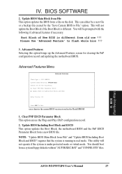
...This can either be prompted with the following : 1. You will not update the Boot Block if the Boot Block is different from a new BIOS file. BIOS (Flash Memory Writer) ASUS P/I-P55T2P4 User's Manual 27 This utility will not operate if the system is running in the Flash EPROM... 1. BIOS SOFTWARE 2. IV. Clear PNP ESCD Parameter Block This option erases the Plug-and-Play (PnP) configuration record. 2. Advanced Features Selecting this option ...
...This can either be prompted with the following : 1. You will not update the Boot Block if the Boot Block is different from a new BIOS file. BIOS (Flash Memory Writer) ASUS P/I-P55T2P4 User's Manual 27 This utility will not operate if the system is running in the Flash EPROM... 1. BIOS SOFTWARE 2. IV. Clear PNP ESCD Parameter Block This option erases the Plug-and-Play (PnP) configuration record. 2. Advanced Features Selecting this option ...


