
NCLV-D Series User Manual English Edition
Page 4
...4: BIOS setup 4.1 Managing and updating your BIOS 4-1 4.1.1 Creating a bootable floppy disk 4-1 4.1.2 AFUDOS utility 4-2 4.1.3 ASUS CrashFree BIOS 2 utility 4-5 4.1.4 ASUS Update utility 4-7 4.2 BIOS setup program 4-10 4.2.1 BIOS menu screen 4-11 4.2.2 Menu bar 4-11 4.2.3 Navigation keys...menu 4-13 4.3.1 System Time 4-13 4.3.2 System Date 4-13 4.3.3 Legacy Diskette A 4-13 4.3.4 Primary, Third and Fourth IDE Master/Slave ......... 4-14 4.3.5 IDE Configuration 4-15 4.3.6 System Information 4-16 4.4 Advanced menu 4-17 4.4.1 USB Configuration 4-17 4.4.2 MPS Configuration 4-18 4.4.3 ...
...4: BIOS setup 4.1 Managing and updating your BIOS 4-1 4.1.1 Creating a bootable floppy disk 4-1 4.1.2 AFUDOS utility 4-2 4.1.3 ASUS CrashFree BIOS 2 utility 4-5 4.1.4 ASUS Update utility 4-7 4.2 BIOS setup program 4-10 4.2.1 BIOS menu screen 4-11 4.2.2 Menu bar 4-11 4.2.3 Navigation keys...menu 4-13 4.3.1 System Time 4-13 4.3.2 System Date 4-13 4.3.3 Legacy Diskette A 4-13 4.3.4 Primary, Third and Fourth IDE Master/Slave ......... 4-14 4.3.5 IDE Configuration 4-15 4.3.6 System Information 4-16 4.4 Advanced menu 4-17 4.4.1 USB Configuration 4-17 4.4.2 MPS Configuration 4-18 4.4.3 ...

NCLV-D Series User Manual English Edition
Page 11
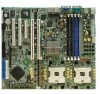
...port (green) 1 x Serial port 2 x LAN (RJ-45) port 2 x USB 2.0 ports 1 x Serial (COM2) port Floppy disk drive connector IDE connector Serial ATA connectors Serial ATA RAID connectors (NCLV-DA model only) SCSI port (NCLV-DS model only) Hard disk activity LED connector Chassis intrusion connector Parallel port connector CPU, Chassis, and Power Fan... (with 24-pin and 8-pin 12 V plugs) ATX 12V 2.0 compliant E-ATX form factor: 12 in x 10.5 in (30.5 cm x 26.7 cm) Device drivers ASUS Server Web-based Management (ASWM) ASUS Live Update Utility *Specifications are subject to change without notice. xi
...port (green) 1 x Serial port 2 x LAN (RJ-45) port 2 x USB 2.0 ports 1 x Serial (COM2) port Floppy disk drive connector IDE connector Serial ATA connectors Serial ATA RAID connectors (NCLV-DA model only) SCSI port (NCLV-DS model only) Hard disk activity LED connector Chassis intrusion connector Parallel port connector CPU, Chassis, and Power Fan... (with 24-pin and 8-pin 12 V plugs) ATX 12V 2.0 compliant E-ATX form factor: 12 in x 10.5 in (30.5 cm x 26.7 cm) Device drivers ASUS Server Web-based Management (ASWM) ASUS Live Update Utility *Specifications are subject to change without notice. xi

NCLV-D Series User Manual English Edition
Page 41
... Clock IRQ holder for PCI steering* IRQ holder for PCI steering* IRQ holder for PCI steering* PS/2 Compatible Mouse Port* Numeric Data Processor Primary IDE Channel Secondary IDE Channel * These IRQs are usually available for the expansion card. See Chapter 4 for information on shared slots, ensure that the drivers support "Share.... When using PCI cards on BIOS setup. 2. Assign an IRQ to the tables on the system and change the necessary BIOS settings, if any. ASUS NCLV-D Series 2-21 Align the card connector with the screw you removed earlier. 6. Turn on the next page. 3. 4.
... Clock IRQ holder for PCI steering* IRQ holder for PCI steering* IRQ holder for PCI steering* PS/2 Compatible Mouse Port* Numeric Data Processor Primary IDE Channel Secondary IDE Channel * These IRQs are usually available for the expansion card. See Chapter 4 for information on shared slots, ensure that the drivers support "Share.... When using PCI cards on BIOS setup. 2. Assign an IRQ to the tables on the system and change the necessary BIOS settings, if any. ASUS NCLV-D Series 2-21 Align the card connector with the screw you removed earlier. 6. Turn on the next page. 3. 4.

NCLV-D Series User Manual English Edition
Page 50
...documentation for the jumper settings. • Pin 20 on the IDE connector is removed to match the covered hole on the connector is for Ultra DMA 100/66 IDE devices. 2-30 SEC_IDE1 PIN 1 PRI_IDE1 PIN 1 NCLV(Series) IDE connectors NOTE: Orient the red markings (usually zigzag) on ... 1. Pin 5 on the Ultra DMA cable connector. Chapter 2: Hardware information NCLV(Series) Floppy disk drive connector 2 . If you install two hard disk drives, you connect the IDE cable. • Use the 80-conductor IDE cable for the provided floppy disk drive (FDD) signal cable. Floppy disk ...
...documentation for the jumper settings. • Pin 20 on the IDE connector is removed to match the covered hole on the connector is for Ultra DMA 100/66 IDE devices. 2-30 SEC_IDE1 PIN 1 PRI_IDE1 PIN 1 NCLV(Series) IDE connectors NOTE: Orient the red markings (usually zigzag) on ... 1. Pin 5 on the Ultra DMA cable connector. Chapter 2: Hardware information NCLV(Series) Floppy disk drive connector 2 . If you install two hard disk drives, you connect the IDE cable. • Use the 80-conductor IDE cable for the provided floppy disk drive (FDD) signal cable. Floppy disk ...

NCLV-D Series User Manual English Edition
Page 51
... "4.3.5 IDE Configuration" on for Serial ATA hard disk drives. NCLV-D NCLV-D SATA connectors SATA2 GND RSATA_TXP2 RSATA_TXN2 GND RSATA_RXP2 RSATA_RXN2 GND SATA1 GND RSATA_TXP1 RSATA_TXN1 GND RSATA_RXP1 RSATA_RXN1 GND (NCLV-DS model only) NCLV-DS NCLV-DS SATA connectors SATA2 GND RSATA_TXP2 RSATA_TXN2 GND RSATA_RXP2 RSATA_RXN2 GND SATA1 GND RSATA_TXP1 RSATA_TXN1 GND RSATA_RXP1 RSATA_RXN1 GND ASUS NCLV-D Series...
... "4.3.5 IDE Configuration" on for Serial ATA hard disk drives. NCLV-D NCLV-D SATA connectors SATA2 GND RSATA_TXP2 RSATA_TXN2 GND RSATA_RXP2 RSATA_RXN2 GND SATA1 GND RSATA_TXP1 RSATA_TXN1 GND RSATA_RXP1 RSATA_RXN1 GND (NCLV-DS model only) NCLV-DS NCLV-DS SATA connectors SATA2 GND RSATA_TXP2 RSATA_TXN2 GND RSATA_RXP2 RSATA_RXN2 GND SATA1 GND RSATA_TXP1 RSATA_TXN1 GND RSATA_RXP1 RSATA_RXN1 GND ASUS NCLV-D Series...

NCLV-D Series User Manual English Edition
Page 54
...cooling fans of 350 mA ~ 740 mA (8.88 W max.) or a total of any device connected to the primary/secondary IDE connectors or the SATA connectors cause this LED to the hard disk activity LED. Do not place jumper caps on the motherboard,...the connector. REAR_FAN1 REAR_FAN2 CPU_FAN1 CPU_FAN2 REAR_FAN1 REAR_FAN2 GND +12V Rotation Rotation +12V GND CPU_FAN1 CPU_FAN2 GND FANPWR2 FANOUT4 GND FANPWR2 FANOUT4 FRNT_FAN1 FRNT_FAN2 NCLV(Series) Fan connectors FRNT_FAN1 FRNT_FAN2 Rotation +12V GND Rotation +12V GND 2-34 Chapter 2: Hardware information The read or write activities of 2.1 ...
...cooling fans of 350 mA ~ 740 mA (8.88 W max.) or a total of any device connected to the primary/secondary IDE connectors or the SATA connectors cause this LED to the hard disk activity LED. Do not place jumper caps on the motherboard,...the connector. REAR_FAN1 REAR_FAN2 CPU_FAN1 CPU_FAN2 REAR_FAN1 REAR_FAN2 GND +12V Rotation Rotation +12V GND CPU_FAN1 CPU_FAN2 GND FANPWR2 FANOUT4 GND FANPWR2 FANOUT4 FRNT_FAN1 FRNT_FAN2 NCLV(Series) Fan connectors FRNT_FAN1 FRNT_FAN2 Rotation +12V GND Rotation +12V GND 2-34 Chapter 2: Hardware information The read or write activities of 2.1 ...

NCLV-D Series User Manual English Edition
Page 60
...color-coded for the system power button. POWERLED+ GND POWERLEDMLED+ MLEDNC +5V GND GND SPKROUT HDLED+ HDLEDNMIBTN# GND POWERBTN# GND NC RESETBTN# GND PANEL1 NCLV(Series) System panel connector The sytem panel connector is for the chassis-mounted reset button for the HDD Activity LED. The system power LED lights... mode depending on the next page for details. • System power LED (Green 3-pin PLED) This 3-pin connector is for easy connection. The IDE LED lights up when you to this connector. 15. The speaker allows you turn on the system power, and blinks when the system is in...
...color-coded for the system power button. POWERLED+ GND POWERLEDMLED+ MLEDNC +5V GND GND SPKROUT HDLED+ HDLEDNMIBTN# GND POWERBTN# GND NC RESETBTN# GND PANEL1 NCLV(Series) System panel connector The sytem panel connector is for the chassis-mounted reset button for the HDD Activity LED. The system power LED lights... mode depending on the next page for details. • System power LED (Green 3-pin PLED) This 3-pin connector is for easy connection. The IDE LED lights up when you to this connector. 15. The speaker allows you turn on the system power, and blinks when the system is in...

NCLV-D Series User Manual English Edition
Page 77
ASUS NCLV-D Series 4-11 Use the navigation keys to select items in ] : [ST320413A] : [ASUS CD-S520/A] : [Not Detected] : [Not Detected] : [Not Detected] : [Not Detected] Use [ENTER], [TAB] or [SHIFT-TAB] to select a field. Some of a ...to another. 4.2.1 BIOS menu screen Menu items Menu bar Configuration fields General help System Time System Date Legacy Diskette A Primary IDE Master Primary IDE Slave Third IDE Master Third IDE Slave Fourth IDE Master Fourth IDE Slave IDE Configuration System Information [11:51:19] [Thu 05/07/2004] [1.44M, 3.5 in the menu and change the settings....
ASUS NCLV-D Series 4-11 Use the navigation keys to select items in ] : [ST320413A] : [ASUS CD-S520/A] : [Not Detected] : [Not Detected] : [Not Detected] : [Not Detected] Use [ENTER], [TAB] or [SHIFT-TAB] to select a field. Some of a ...to another. 4.2.1 BIOS menu screen Menu items Menu bar Configuration fields General help System Time System Date Legacy Diskette A Primary IDE Master Primary IDE Slave Third IDE Master Third IDE Slave Fourth IDE Master Fourth IDE Slave IDE Configuration System Information [11:51:19] [Thu 05/07/2004] [1.44M, 3.5 in the menu and change the settings....

NCLV-D Series User Manual English Edition
Page 78
... menu items. 4.2.5 Sub-menu items System Time System Date Legacy Diskette A Language Primary IDE Master Primary IDE Slave Secondary IDE Master Secondary IDE Slave Third IDE Master Fourth IDE Master IDE Configuration System Information [11:10:19] [Thu 03/27/2003] [1.44M, 3.5 in] [English] :[ST320413A] :[ASUS CD-S340] :[Not Detected] :[Not Detected] :[Not Detected] :[Not Detected] Main menu...
... menu items. 4.2.5 Sub-menu items System Time System Date Legacy Diskette A Language Primary IDE Master Primary IDE Slave Secondary IDE Master Secondary IDE Slave Third IDE Master Fourth IDE Master IDE Configuration System Information [11:10:19] [Thu 03/27/2003] [1.44M, 3.5 in] [English] :[ST320413A] :[ASUS CD-S340] :[Not Detected] :[Not Detected] :[Not Detected] :[Not Detected] Main menu...

NCLV-D Series User Manual English Edition
Page 79
...set the system date. 4.3.3 Legacy Diskette A [1.44M, 3.5 in .] ASUS NCLV-D Series 4-13 System Time System Date Legacy Diskette A Primary IDE Master Primary IDE Slave Third IDE Master Third IDE Slave Fourth IDE Master Fourth IDE Slave IDE Configuration System Information [11:51:19] [Thu 05/07/2004] [1.44M..., 3.5 in] : [ST320413A] : [ASUS CD-S520/A] : [Not Detected] : [Not ...
...set the system date. 4.3.3 Legacy Diskette A [1.44M, 3.5 in .] ASUS NCLV-D Series 4-13 System Time System Date Legacy Diskette A Primary IDE Master Primary IDE Slave Third IDE Master Third IDE Slave Fourth IDE Master Fourth IDE Slave IDE Configuration System Information [11:51:19] [Thu 05/07/2004] [1.44M..., 3.5 in] : [ST320413A] : [ASUS CD-S520/A] : [Not Detected] : [Not ...

NCLV-D Series User Manual English Edition
Page 80
... the LBA mode. When set to [Disabled], the data transfer from and to the device occurs multiple sectors at a time. These items show N/A if no IDE device is either a ZIP, LS-120, or MO drive. Select [ARMD] (ATAPI Removable Media Device) if your device is installed in the system. Select ... (Device, Vendor, Size, LBA Mode, Block Mode, PIO Mode, Async DMA, Ultra DMA, and SMART monitoring). Type [Auto] Selects the type of the appropriate IDE device type. Select [CDROM] if you are not user-configurable. When set to [Auto], the data transfer from and to [Auto] enables the LBA mode...
... the LBA mode. When set to [Disabled], the data transfer from and to the device occurs multiple sectors at a time. These items show N/A if no IDE device is either a ZIP, LS-120, or MO drive. Select [ARMD] (ATAPI Removable Media Device) if your device is installed in the system. Select ... (Device, Vendor, Size, LBA Mode, Block Mode, PIO Mode, Async DMA, Ultra DMA, and SMART monitoring). Type [Auto] Selects the type of the appropriate IDE device type. Select [CDROM] if you are not user-configurable. When set to [Auto], the data transfer from and to [Auto] enables the LBA mode...

NCLV-D Series User Manual English Edition
Page 81
...The items in AHCI/RAID mode SATA controller is recommend that you may use native OS on Serial ATA and Parallel ATA ports. IDE Configuration Onboard IDE Operate Mode Enhanced Mode Support On Configure S-ATA as RAID [No] Allows you do not change the configurations for better OS compatibility...you are using native OS including Windows® 2000/XP. PIO Mode [Auto] Selects the PIO mode. Configuration options: [No] [Yes] ASUS NCLV-D Series 4-15 Configuration options: [Auto] [0] [1] [2] [3] [4] SMART Monitoring [Auto] Sets the Smart Monitoring, Analysis, and Reporting Technology.
...The items in AHCI/RAID mode SATA controller is recommend that you may use native OS on Serial ATA and Parallel ATA ports. IDE Configuration Onboard IDE Operate Mode Enhanced Mode Support On Configure S-ATA as RAID [No] Allows you do not change the configurations for better OS compatibility...you are using native OS including Windows® 2000/XP. PIO Mode [Auto] Selects the PIO mode. Configuration options: [No] [Yes] ASUS NCLV-D Series 4-15 Configuration options: [Auto] [0] [1] [2] [3] [4] SMART Monitoring [Auto] Sets the Smart Monitoring, Analysis, and Reporting Technology.

NCLV-D Series User Manual English Edition
Page 82
...r t s O n l y options are for detecting ATA/ATAPI devices. A T A. Configuration options: [Primary P-ATA+S-ATA] [Secondary P-ATA+S-ATA] [P-ATA Ports Only] IDE Detect Time Out [35] Selects the time out value for advanced users only. A T A and P - Configuration options: [0] [5] [10] [15] [20] [25]... and encountered problems, revert to the default setting P r i m a r y P - The Secondary P - If you to select the combined mode for the installed IDE and SATA devices. A T A + S - The BIOS automatically detects the items in this menu. A T A + S - AMIBIOS Version : 08.00.10 Build...
...r t s O n l y options are for detecting ATA/ATAPI devices. A T A. Configuration options: [Primary P-ATA+S-ATA] [Secondary P-ATA+S-ATA] [P-ATA Ports Only] IDE Detect Time Out [35] Selects the time out value for advanced users only. A T A and P - Configuration options: [0] [5] [10] [15] [20] [25]... and encountered problems, revert to the default setting P r i m a r y P - The Secondary P - If you to select the combined mode for the installed IDE and SATA devices. A T A + S - The BIOS automatically detects the items in this menu. A T A + S - AMIBIOS Version : 08.00.10 Build...

NCLV-D Series User Manual English Edition
Page 90
... PnP menu items. Incorrect field values can function correctly. Plug And Play O/S PCI Latency Timer Allocate IRQ to PCI VGA Palette Snooping PCI IDE BusMaster OffBoard PCI/ISA IDE Card [No] [64] [Yes] [Disabled] [Enabled] [Auto] IRQ-3 assigned to IRQ-4 assigned to IRQ-5 assigned to IRQ-7 assigned to IRQ-9 assigned to IRQ...
... PnP menu items. Incorrect field values can function correctly. Plug And Play O/S PCI Latency Timer Allocate IRQ to PCI VGA Palette Snooping PCI IDE BusMaster OffBoard PCI/ISA IDE Card [No] [64] [Yes] [Disabled] [Enabled] [Auto] IRQ-3 assigned to IRQ-4 assigned to IRQ-5 assigned to IRQ-7 assigned to IRQ-9 assigned to IRQ...

NCLV-D Series User Manual English Edition
Page 91
...PCI Device] [PCI Device] [PCI Device] [Disabled] Select Screen Select Item +- Configuration options: [Disabled] [Enabled] Offboard PCI/ISA IDE Card [Auto] Allows you to set to IDE devices. Change Option F1 General Help F10 Save and Exit ESC Exit DMA Channel X assigned to [PCI Device] When set to [...when reading/writing to [PCI Device], the specific IRQ is free for legacy ISA devices. Configuration options: [Disabled] [16k] [32k] [64k] ASUS NCLV-D Series 4-25 Configuration options: [Auto] [PCI Slot1] [PCI Slot2] [PCI Slot3] [PCI Slot4] [PCI Slot5] [PCI Slot6] IRQ-xx assigned to a...
...PCI Device] [PCI Device] [PCI Device] [Disabled] Select Screen Select Item +- Configuration options: [Disabled] [Enabled] Offboard PCI/ISA IDE Card [Auto] Allows you to set to IDE devices. Change Option F1 General Help F10 Save and Exit ESC Exit DMA Channel X assigned to [PCI Device] When set to [...when reading/writing to [PCI Device], the specific IRQ is free for legacy ISA devices. Configuration options: [Disabled] [16k] [32k] [64k] ASUS NCLV-D Series 4-25 Configuration options: [Auto] [PCI Slot1] [PCI Slot2] [PCI Slot3] [PCI Slot4] [PCI Slot5] [PCI Slot6] IRQ-xx assigned to a...


