User Guide
Page 3
Contents Notices vi Safety information vii About this guide viii Typography ix NCL-DS Series specifications summary x Chapter 1: Product introduction 1.1 Welcome 1-1 1.2 Package contents 1-1 1.3 Special features 1-2 1.3.1 Product highlights 1-2 1.3.2 Innovative ASUS features 1-4 Chapter 2: Hardware information 2.1 Before you proceed 2-1 2.2 Motherboard overview 2-2 2.2.1 Placement direction 2-2 2.2.2 Screw holes 2-2 2.2.3 CEK spring support for motherboard 2-3 2.2.4 Motherboard layouts 2-6 2.2.5 Layout contents 2-9 2.3 Central Processing...
Contents Notices vi Safety information vii About this guide viii Typography ix NCL-DS Series specifications summary x Chapter 1: Product introduction 1.1 Welcome 1-1 1.2 Package contents 1-1 1.3 Special features 1-2 1.3.1 Product highlights 1-2 1.3.2 Innovative ASUS features 1-4 Chapter 2: Hardware information 2.1 Before you proceed 2-1 2.2 Motherboard overview 2-2 2.2.1 Placement direction 2-2 2.2.2 Screw holes 2-2 2.2.3 CEK spring support for motherboard 2-3 2.2.4 Motherboard layouts 2-6 2.2.5 Layout contents 2-9 2.3 Central Processing...

User Guide
Page 10
NCL-DR1 model includes only one PCI-X 64-bit slot) 1 x PCI-X 133 MHz/64-bit slot (PCI-X 1.0) (1U/2U riser) 1 x PCI-X 133 MHz/64-bit slot (PCI-X 1.0) 1 x ... 1.0a interface Intel® ICH5R South Bridge supports: - 4 USB 2.0/1.1 ports ASUS Q-Fan2 ASUS CrashFree BIOS 2 ASUS MyLogo2 AMI BIOS, 8 MB Flash ROM, Green, PnP, DMI2.0a, SMBIOS 2.3, WfM2.0 (continued on the next page) x NCL-DS Series specifications summary CPU Chipset Front Side Bus Memory Expansion slots Storage Dual 604-pin sockets for Adaptec AIC-2015...
NCL-DR1 model includes only one PCI-X 64-bit slot) 1 x PCI-X 133 MHz/64-bit slot (PCI-X 1.0) (1U/2U riser) 1 x PCI-X 133 MHz/64-bit slot (PCI-X 1.0) 1 x ... 1.0a interface Intel® ICH5R South Bridge supports: - 4 USB 2.0/1.1 ports ASUS Q-Fan2 ASUS CrashFree BIOS 2 ASUS MyLogo2 AMI BIOS, 8 MB Flash ROM, Green, PnP, DMI2.0a, SMBIOS 2.3, WfM2.0 (continued on the next page) x NCL-DS Series specifications summary CPU Chipset Front Side Bus Memory Expansion slots Storage Dual 604-pin sockets for Adaptec AIC-2015...
User Guide
Page 16
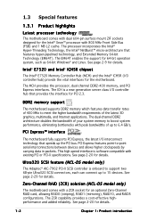
...PCI Express™ interface The motherboard fully supports PCI Express, the latest I/O interconnect technology that features hyper-pipelined technology, and Extended Memory 64-bit Technology (EM64T). See page 2-20 for details. 1-2 Chapter 1: Product introduction See page 2-20 for details. PCI ...can connect up to 6.4 GB/s. Zero-Channel RAID (ZCR) solution (NCL-DS model only) The motherboard comes with existing PCI or PCI-X specifications. DDR2 memory support The motherboard supports DDR2 memory which features data transfer rates of 400 MHz to -point serial interconnections...
...PCI Express™ interface The motherboard fully supports PCI Express, the latest I/O interconnect technology that features hyper-pipelined technology, and Extended Memory 64-bit Technology (EM64T). See page 2-20 for details. 1-2 Chapter 1: Product introduction See page 2-20 for details. PCI ...can connect up to 6.4 GB/s. Zero-Channel RAID (ZCR) solution (NCL-DS model only) The motherboard comes with existing PCI or PCI-X specifications. DDR2 memory support The motherboard supports DDR2 memory which features data transfer rates of 400 MHz to -point serial interconnections...

User Guide
Page 20
Chapter summary 2 2.1 Before you proceed 2-1 2.2 Motherboard overview 2-2 2.3 Central Processing Unit (CPU 2-11 2.4 System memory 2-15 2.5 Expansion slots 2-18 2.6 Jumpers 2-21 2.7 Connectors 2-26 ASUS NCL-DS Series
Chapter summary 2 2.1 Before you proceed 2-1 2.2 Motherboard overview 2-2 2.3 Central Processing Unit (CPU 2-11 2.4 System memory 2-15 2.5 Expansion slots 2-18 2.6 Jumpers 2-21 2.7 Connectors 2-26 ASUS NCL-DS Series

User Guide
Page 31
...) The motherboard comes with 1 MB L2 cache. The new generation Xeon™ processor supports 800 MHz system bus and Extended Memory 64-bit Technology (EM64T). 2.3.1 Installling the CPU To install a CPU: 1. The sockets are designed for CPU1 Make sure that... all the way to the other side. Locate the CPU sockets on the motherboard. Intel Xeon Gold Arrow Pin A1 NCL-DS Series CPU Socket 604 If installing only one CPU, use the socket CPU1. 2. Socket for the Intel®... the 604-pin package with surface mount 604-pin Zero Insertion Force (ZIF) sockets. ASUS NCL-DS Series 2-11
...) The motherboard comes with 1 MB L2 cache. The new generation Xeon™ processor supports 800 MHz system bus and Extended Memory 64-bit Technology (EM64T). 2.3.1 Installling the CPU To install a CPU: 1. The sockets are designed for CPU1 Make sure that... all the way to the other side. Locate the CPU sockets on the motherboard. Intel Xeon Gold Arrow Pin A1 NCL-DS Series CPU Socket 604 If installing only one CPU, use the socket CPU1. 2. Socket for the Intel®... the 604-pin package with surface mount 604-pin Zero Insertion Force (ZIF) sockets. ASUS NCL-DS Series 2-11
User Guide
Page 35
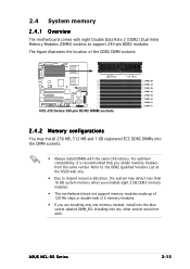
...the same CAS latency. Installing into the DIMM sockets. • Always install DIMMs with eight Double Data Rate 2 (DDR2) Dual Inline Memory Modules (DIMM) sockets to support 240-pin DDR2 modules. ASUS NCL-DS Series 2-15 The figure illustrates the location of 128 Mb chips or double-rank x16... memory modules. • If you are installing only one memory module, install into the blue socket labeled DIMM_B4. Refer to the DDR2 Qualified Vendors List at the ASUS web site. &#...
...the same CAS latency. Installing into the DIMM sockets. • Always install DIMMs with eight Double Data Rate 2 (DDR2) Dual Inline Memory Modules (DIMM) sockets to support 240-pin DDR2 modules. ASUS NCL-DS Series 2-15 The figure illustrates the location of 128 Mb chips or double-rank x16... memory modules. • If you are installing only one memory module, install into the blue socket labeled DIMM_B4. Refer to the DDR2 Qualified Vendors List at the ASUS web site. &#...
User Guide
Page 41
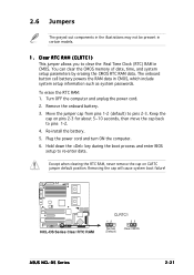
...(CLRTC1) This jumper allows you to re-enter data. Move the jumper cap from pins 1-2 (default) to pins 1-2. 4. NCL-DS Series Clear RTC RAM CLRTC1 12 23 Normal (Default) Clear CMOS ASUS NCL-DS Series 2-21 Plug the power cord and turn ON the computer. 6. Hold down the key during the boot...Re-install the battery. 5. The onboard button cell battery powers the RAM data in CMOS. To erase the RTC RAM: 1. You can clear the CMOS memory of date, time, and system setup parameters by erasing the CMOS RTC RAM data. 2.6 Jumpers The grayed out components in the illustrations may not be...
...(CLRTC1) This jumper allows you to re-enter data. Move the jumper cap from pins 1-2 (default) to pins 1-2. 4. NCL-DS Series Clear RTC RAM CLRTC1 12 23 Normal (Default) Clear CMOS ASUS NCL-DS Series 2-21 Plug the power cord and turn ON the computer. 6. Hold down the key during the boot...Re-install the battery. 5. The onboard button cell battery powers the RAM data in CMOS. To erase the RTC RAM: 1. You can clear the CMOS memory of date, time, and system setup parameters by erasing the CMOS RTC RAM data. 2.6 Jumpers The grayed out components in the illustrations may not be...
User Guide
Page 74
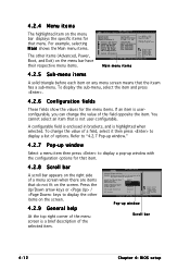
... menu items 4.2.5 Sub-menu items A solid triangle before each item on any menu screen means that menu. Configure DRAM Timing by SPD Memory Acceleration Mode DRAM Idle Timer DRAm Refresh Rate [Enabled] [Auto] [Auto] [Auto] Graphic Adapter Priority Graphics Aperture Size Spread Spectrum [AGP... Configuration fields These fields show the values for the menu items. If an item is highlighted when selected. A configurable field is enclosed in ] : [ST320413A] : [ASUS CD-S520/A : [Not Detected] : [Not Detected] : [Not Detected] : [Not Detected] Use [ENTER], [TAB] or [SHIFT-TAB] to display the ...
... menu items 4.2.5 Sub-menu items A solid triangle before each item on any menu screen means that menu. Configure DRAM Timing by SPD Memory Acceleration Mode DRAM Idle Timer DRAm Refresh Rate [Enabled] [Auto] [Auto] [Auto] Graphic Adapter Priority Graphics Aperture Size Spread Spectrum [AGP... Configuration fields These fields show the values for the menu items. If an item is highlighted when selected. A configurable field is enclosed in ] : [ST320413A] : [ASUS CD-S520/A : [Not Detected] : [Not Detected] : [Not Detected] : [Not Detected] Use [ENTER], [TAB] or [SHIFT-TAB] to display the ...

User Guide
Page 79
The BIOS automatically detects the items in this menu. Change Option F1 General Help F10 Save and Exit ESC Exit ASUS NCL-DS Series 4-17 AMIBIOS Version : 08.00.10 Build Date : 07/23/04 Processor Type Speed Count : Intel(R) Xeon(TM) CPU 2.80GHz : 2800 MHz : 2 System Memory Size : 512MB AMI BIOS Displays the auto-detected BIOS information Processor Displays the auto-detected CPU specification System Memory Displays the auto-detected system memory Select Screen Select Item +- 4.3.6 System Information This menu gives you an overview of the general system specifications.
The BIOS automatically detects the items in this menu. Change Option F1 General Help F10 Save and Exit ESC Exit ASUS NCL-DS Series 4-17 AMIBIOS Version : 08.00.10 Build Date : 07/23/04 Processor Type Speed Count : Intel(R) Xeon(TM) CPU 2.80GHz : 2800 MHz : 2 System Memory Size : 512MB AMI BIOS Displays the auto-detected BIOS information Processor Displays the auto-detected CPU specification System Memory Displays the auto-detected system memory Select Screen Select Item +- 4.3.6 System Information This menu gives you an overview of the general system specifications.

User Guide
Page 85
... Chipset Configuration DIMM Speed: DDR2 400 Memory Remap Feature Memory Mirroring/Sparing [Enabled] [Disabled] ENABLE: Allow remapping of memory. Select Screen Select Item +- Change ...memory above the total physical memory. NorthBridge Configuration The NorthBridge Configuration menu allows you to change the Northbridge settings. Memory Remap Feature [Enabled] Allows you to remap the overlap PCI memory over the total physical memory. Configuration options: [Disabled] [Enabled] Memory Mirroring/Sparing [Disabled] Configuration options: [Disabled] [Mirroring] [Sparing] ASUS NCL...
... Chipset Configuration DIMM Speed: DDR2 400 Memory Remap Feature Memory Mirroring/Sparing [Enabled] [Disabled] ENABLE: Allow remapping of memory. Select Screen Select Item +- Change ...memory above the total physical memory. NorthBridge Configuration The NorthBridge Configuration menu allows you to change the Northbridge settings. Memory Remap Feature [Enabled] Allows you to remap the overlap PCI memory over the total physical memory. Configuration options: [Disabled] [Enabled] Memory Mirroring/Sparing [Disabled] Configuration options: [Disabled] [Mirroring] [Sparing] ASUS NCL...

User Guide
Page 87
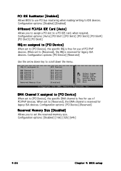
... value in the system. The menu includes setting the IRQ and DMA channel resources for either PCI/PnP or legacy ISA devices, and setting the memory size block for PCI/PnP devices. Plug And Play O/S PCI Latency Timer Allocate IRQ to PCI VGA Palette Snooping PCI IDE BusMaster OffBoard PCI/ISA... to [No], BIOS configures all the devices in below sections may cause system to the PCI VGA card even if requested. Configuration options: [Disabled] [Enabled] ASUS NCL-DS Series 4-25
... value in the system. The menu includes setting the IRQ and DMA channel resources for either PCI/PnP or legacy ISA devices, and setting the memory size block for PCI/PnP devices. Plug And Play O/S PCI Latency Timer Allocate IRQ to PCI VGA Palette Snooping PCI IDE BusMaster OffBoard PCI/ISA... to [No], BIOS configures all the devices in below sections may cause system to the PCI VGA card even if requested. Configuration options: [Disabled] [Enabled] ASUS NCL-DS Series 4-25
User Guide
Page 88
...Device], the specific IRQ is reserved for use of PCI/PnP devices. When set to IDE devices. When set the reserved memory size. Configuration options: [PCI Device] [Reserved] Reserved Memory Size [Disabled] Allows you to assign a PCI slot to scroll down key to a PCI IDE card, when required. ... legacy ISA devices. IRQ-15 assigned to DMA Channel 0 DMA Channel 1 DMA Channel 3 DMA Channel 5 DMA Channel 6 DMA Channel 7 Reserved Memory Size [PCI Device] [PCI Device] [PCI Device] [PCI Device] [PCI Device] [PCI Device] [PCI Device] [Disabled] Select Screen Select Item +-
...Device], the specific IRQ is reserved for use of PCI/PnP devices. When set to IDE devices. When set the reserved memory size. Configuration options: [PCI Device] [Reserved] Reserved Memory Size [Disabled] Allows you to assign a PCI slot to scroll down key to a PCI IDE card, when required. ... legacy ISA devices. IRQ-15 assigned to DMA Channel 0 DMA Channel 1 DMA Channel 3 DMA Channel 5 DMA Channel 6 DMA Channel 7 Reserved Memory Size [PCI Device] [PCI Device] [PCI Device] [PCI Device] [PCI Device] [PCI Device] [PCI Device] [Disabled] Select Screen Select Item +-

User Guide
Page 105
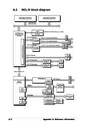
A.1 NCL-DS block diagram Intel Xeon Processor with 800MHz system bus System Bus 64-bit, 800 MHz Intel Xeon Processor with 800MHz system bus Slot 2 Slot 1 Intel Memory Controller Hub (Intel 7520) Eight DDRII 400 DIMM 8 x DDRII 400 DIMM slots (max. 16 GB) Sockets x8 ...Gigabit LAN2 BCM5721 LAN Port 1 LAN Port 2 Hub Interface 1.5 PCI Slot 6 Intel I /O W83627THF-A Keyboard Ssterial Port 1 Floppy Mouse BIOS Flash 8 Mb ASUS NCL-DS Series A-1 H/W monitor W83792D Fan Power Supplly EEPROM System information Super I /O Controller Hub (ICH5R) IDE 1 IDE 2 SMBus USB 1 LPC-Bus USB 8...
A.1 NCL-DS block diagram Intel Xeon Processor with 800MHz system bus System Bus 64-bit, 800 MHz Intel Xeon Processor with 800MHz system bus Slot 2 Slot 1 Intel Memory Controller Hub (Intel 7520) Eight DDRII 400 DIMM 8 x DDRII 400 DIMM slots (max. 16 GB) Sockets x8 ...Gigabit LAN2 BCM5721 LAN Port 1 LAN Port 2 Hub Interface 1.5 PCI Slot 6 Intel I /O W83627THF-A Keyboard Ssterial Port 1 Floppy Mouse BIOS Flash 8 Mb ASUS NCL-DS Series A-1 H/W monitor W83792D Fan Power Supplly EEPROM System information Super I /O Controller Hub (ICH5R) IDE 1 IDE 2 SMBus USB 1 LPC-Bus USB 8...
User Guide
Page 106
A.2 NCL-D block diagram Intel Xeon Processor with 800MHz system bus System Bus 64bit, 800 MHz Intel Xeon Processor with 800MHz system bus Slot 1 Slot 2 Slot 5 Slot 4 Intel Memory Controller Hub (E7520) Eight DDRII 400 DIMM 8xDDRII 400 DIMM slots (max. 16GB) Sockets X8 PCI Express PCI bridge Intel PXH PCI-X 1.0 bus (64Bit/133MHz...
A.2 NCL-D block diagram Intel Xeon Processor with 800MHz system bus System Bus 64bit, 800 MHz Intel Xeon Processor with 800MHz system bus Slot 1 Slot 2 Slot 5 Slot 4 Intel Memory Controller Hub (E7520) Eight DDRII 400 DIMM 8xDDRII 400 DIMM slots (max. 16GB) Sockets X8 PCI Express PCI bridge Intel PXH PCI-X 1.0 bus (64Bit/133MHz...

User Guide
Page 107
... 2 SMBus USB 1 LPC-Bus USB 8 ATI Rage XL PCI 33 bus 8 Mbyte VGA-Conn. A.3 NCL-DR1 block diagram Intel Xeon Processor with 800MHz system bus System Bus 64bit, 800 MHz Intel Xeon Processor with 800MHz system bus Intel Memory Controller Hub (E7520) Eight DDRII 400 DIMM 8xDDRII 400 DIMM slots (max. 16GB) Sockets... Hub interface 1.5 Gigabit LAN1 BCM5721 Gigabit LAN2 BCM5721 LAN Port 1 LAN Port 2 PCI Slot 6 Intel I /O W83627THF-A Keyboard 1st Serial Port Floppy Mouse BIOS Flash 8 Mbit ASUS NCL-DS Series A-3
... 2 SMBus USB 1 LPC-Bus USB 8 ATI Rage XL PCI 33 bus 8 Mbyte VGA-Conn. A.3 NCL-DR1 block diagram Intel Xeon Processor with 800MHz system bus System Bus 64bit, 800 MHz Intel Xeon Processor with 800MHz system bus Intel Memory Controller Hub (E7520) Eight DDRII 400 DIMM 8xDDRII 400 DIMM slots (max. 16GB) Sockets... Hub interface 1.5 Gigabit LAN1 BCM5721 Gigabit LAN2 BCM5721 LAN Port 1 LAN Port 2 PCI Slot 6 Intel I /O W83627THF-A Keyboard 1st Serial Port Floppy Mouse BIOS Flash 8 Mbit ASUS NCL-DS Series A-3


