
User Manual
Page 15
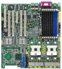
... in -1 floppy disk drive cable Accessories Application CDs Documentation 2 x CEK springs (for the following items. Motherboard ASUS NCL-DE Series motherboard Cables 2 x Serial ATA signal cables 1 x Serial ATA power cable (dual-plug) 2 x SCSI Ultra320 cable (NCL-DE/SCSI model only) 80-conductor IDE cable 3-in the long line of the above items is...
... in -1 floppy disk drive cable Accessories Application CDs Documentation 2 x CEK springs (for the following items. Motherboard ASUS NCL-DE Series motherboard Cables 2 x Serial ATA signal cables 1 x Serial ATA power cable (dual-plug) 2 x SCSI Ultra320 cable (NCL-DE/SCSI model only) 80-conductor IDE cable 3-in the long line of the above items is...
User Manual
Page 17
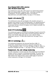
... page 2-28 for details. The ASIC monitors the voltage levels to ensure stable supply of current for timely failure detection. Zero-Channel RAID (ZCR) solution (NCL-DE/SCSI model only) The motherboard comes with dual Gigabit LAN controllers and ports to provide a total solution for your networking needs. The ZCR capability... voltage monitoring The CPU temperature is monitored for critical components. See page 2-19 for details. See page 4-30 for thinner, more flexible cables with USB 1.1. ASUS NCL-DE Series 1-3
... page 2-28 for details. The ASIC monitors the voltage levels to ensure stable supply of current for timely failure detection. Zero-Channel RAID (ZCR) solution (NCL-DE/SCSI model only) The motherboard comes with dual Gigabit LAN controllers and ports to provide a total solution for your networking needs. The ZCR capability... voltage monitoring The CPU temperature is monitored for critical components. See page 2-19 for details. See page 4-30 for thinner, more flexible cables with USB 1.1. ASUS NCL-DE Series 1-3
User Manual
Page 20
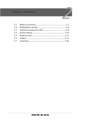
Chapter summary 2 2.1 Before you proceed 2-1 2.2 Motherboard overview 2-2 2.3 Central Processing Unit (CPU 2-10 2.4 System memory 2-14 2.5 Expansion slots 2-17 2.6 Jumpers 2-21 2.7 Connectors 2-26 ASUS NCL-DE Series
Chapter summary 2 2.1 Before you proceed 2-1 2.2 Motherboard overview 2-2 2.3 Central Processing Unit (CPU 2-10 2.4 System memory 2-14 2.5 Expansion slots 2-17 2.6 Jumpers 2-21 2.7 Connectors 2-26 ASUS NCL-DE Series

User Manual
Page 21
... with a standby power LED. The green LED lights up to indicate that the system is switched off mode. NCL-DE Series ® SB_PWR1 ON Standby Power OFF Powered Off NCL-DE Series Standby power LED ASUS NCL-DE Series 2-1 Onboard LED The motherboard comes with the component. • Before you install or remove any...
... with a standby power LED. The green LED lights up to indicate that the system is switched off mode. NCL-DE Series ® SB_PWR1 ON Standby Power OFF Powered Off NCL-DE Series Standby power LED ASUS NCL-DE Series 2-1 Onboard LED The motherboard comes with the component. • Before you install or remove any...
User Manual
Page 23
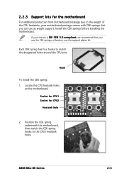
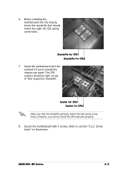
... the motherboard, then match the CEK spring hooks to match the designated holes around the CPU area. Locate the CPU heatsink holes on the motherboard. ASUS NCL-DE Series 2-3 Hook To install the CEK spring: 1. Each CEK spring has four hooks to the CPU1 heatsink holes. Socket for CPU1 Socket for the...
... the motherboard, then match the CEK spring hooks to match the designated holes around the CPU area. Locate the CPU heatsink holes on the motherboard. ASUS NCL-DE Series 2-3 Hook To install the CEK spring: 1. Each CEK spring has four hooks to the CPU1 heatsink holes. Socket for CPU1 Socket for the...
User Manual
Page 25
..., you can not install the CPU heatsinks properly. 8. Standoffs for CPU1 Standoffs for illustration. The CPU sockets should match the eight (8) CEK spring screw holes. ASUS NCL-DE Series 2-5 6.
..., you can not install the CPU heatsinks properly. 8. Standoffs for CPU1 Standoffs for illustration. The CPU sockets should match the eight (8) CEK spring screw holes. ASUS NCL-DE Series 2-5 6.
User Manual
Page 31
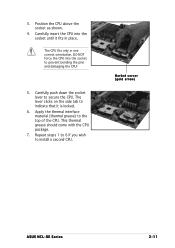
... lever to install a second CPU. Repeat steps 1 to 6 if you wish to secure the CPU. The CPU fits only in place. Marked corner (gold arrow) ASUS NCL-DE Series 2-11 The lever clicks on the side tab to indicate that it fits in one correct orientation. 3. Position the CPU above the socket...
... lever to install a second CPU. Repeat steps 1 to 6 if you wish to secure the CPU. The CPU fits only in place. Marked corner (gold arrow) ASUS NCL-DE Series 2-11 The lever clicks on the side tab to indicate that it fits in one correct orientation. 3. Position the CPU above the socket...
User Manual
Page 33
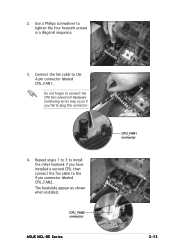
Do not forget to tighten the four heatsink screws in a diagonal sequence. 3. CPU_FAN2 connector ASUS NCL-DE Series CPU_FAN1 connector 2-13 Hardware monitoring errors may occur if you have installed a second CPU, then connect the fan cable to the 4-pin connector labeled CPU_FAN2. Use a Phillips screwdriver to connect the CPU fan connector! The heatsinks appear as shown when installed. Repeat steps 1 to 3 to install the other heatsink if you fail to the 4-pin connector labeled CPU_FAN1. Connect the fan cable to plug this connector. 4. 2.
Do not forget to tighten the four heatsink screws in a diagonal sequence. 3. CPU_FAN2 connector ASUS NCL-DE Series CPU_FAN1 connector 2-13 Hardware monitoring errors may occur if you have installed a second CPU, then connect the fan cable to the 4-pin connector labeled CPU_FAN2. Use a Phillips screwdriver to connect the CPU fan connector! The heatsinks appear as shown when installed. Repeat steps 1 to 3 to install the other heatsink if you fail to the 4-pin connector labeled CPU_FAN1. Connect the fan cable to plug this connector. 4. 2.
User Manual
Page 35
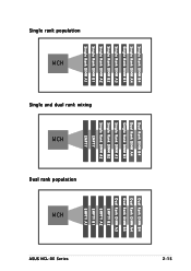
Single rank population MCH Single and dual rank mixing MCH Dual rank population MCH ASUS NCL-DE Series Single Rank DIMM B4 Single Rank DIMM A4 Single Rank DIMM B3 Single Rank DIMM A3 Single Rank DIMM B2 Single Rank DIMM A2 Single Rank DIMM B1 Single Rank DIMM A1 Dual Rank DIMM B4 Dual Rank DIMM A4 Single Rank DIMM B3 Single Rank DIMM A3 Single Rank DIMM B2 Single Rank DIMM A2 EMPTY EMPTY Dual Rank DIMM B4 Dual Rank DIMM A4 Dual Rank DIMM B3 Dual Rank DIMM A3 EMPTY B2 EMPTY A2 EMPTY B1 EMPTY A1 2-15
Single rank population MCH Single and dual rank mixing MCH Dual rank population MCH ASUS NCL-DE Series Single Rank DIMM B4 Single Rank DIMM A4 Single Rank DIMM B3 Single Rank DIMM A3 Single Rank DIMM B2 Single Rank DIMM A2 Single Rank DIMM B1 Single Rank DIMM A1 Dual Rank DIMM B4 Dual Rank DIMM A4 Single Rank DIMM B3 Single Rank DIMM A3 Single Rank DIMM B2 Single Rank DIMM A2 EMPTY EMPTY Dual Rank DIMM B4 Dual Rank DIMM A4 Dual Rank DIMM B3 Dual Rank DIMM A3 EMPTY B2 EMPTY A2 EMPTY B1 EMPTY A1 2-15
User Manual
Page 37
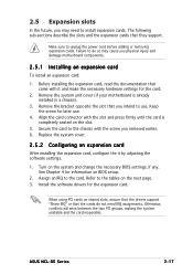
..., you may cause you physical injury and damage motherboard components. 2.5.1 Installing an expansion card To install an expansion card: 1. See Chapter 4 for the expansion card. ASUS NCL-DE Series 2-17
..., you may cause you physical injury and damage motherboard components. 2.5.1 Installing an expansion card To install an expansion card: 1. See Chapter 4 for the expansion card. ASUS NCL-DE Series 2-17
User Manual
Page 39
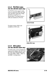
ASUS NCL-DE Series 2-19 The figure shows a RAID card installed on a PCI-X slot. 32-bit PCI slot 64-bit PCI-X slot 2.5.5 ZCR socket (For NCL-DE/SCSI model only) The ZCR socket on a PCI slot. The figure shows a LAN card installed on the motherboard supports the Adaptec AIC-2015 and AIC-2025 Zero-Channel RAID cards that comply with PCI 2.3 and PCI-X 1.0 specifications. 2.5.4 PCI/PCI-X slots (For NCL-DE/SCSI model only) The PCI/PCI-X slots support cards such as a LAN card, SCSI card, USB card, and other cards that allow RAID 0, RAID 1, RAID 10, and RAID 5 configurations.
ASUS NCL-DE Series 2-19 The figure shows a RAID card installed on a PCI-X slot. 32-bit PCI slot 64-bit PCI-X slot 2.5.5 ZCR socket (For NCL-DE/SCSI model only) The ZCR socket on a PCI slot. The figure shows a LAN card installed on the motherboard supports the Adaptec AIC-2015 and AIC-2025 Zero-Channel RAID cards that comply with PCI 2.3 and PCI-X 1.0 specifications. 2.5.4 PCI/PCI-X slots (For NCL-DE/SCSI model only) The PCI/PCI-X slots support cards such as a LAN card, SCSI card, USB card, and other cards that allow RAID 0, RAID 1, RAID 10, and RAID 5 configurations.
User Manual
Page 41
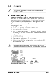
... data. Turn OFF the computer and unplug the power cord. 2. Keep the cap on CLRTC jumper default position. NCL-DE Series ® NCL-DE Series Clear RTC RAM CLRTC1 21 32 Normal Clear CMOS (Default) ASUS NCL-DE Series 2-21 Plug the power cord and turn ON the computer. 6. To erase the RTC RAM... (RTC) RAM in CMOS, which include system setup information such as system passwords. 2.6 Jumpers The grayed out components in the illustrations are present only in NCL-DE/SCSI model. 1. Removing the cap will cause system boot failure!
... data. Turn OFF the computer and unplug the power cord. 2. Keep the cap on CLRTC jumper default position. NCL-DE Series ® NCL-DE Series Clear RTC RAM CLRTC1 21 32 Normal Clear CMOS (Default) ASUS NCL-DE Series 2-21 Plug the power cord and turn ON the computer. 6. To erase the RTC RAM... (RTC) RAM in CMOS, which include system setup information such as system passwords. 2.6 Jumpers The grayed out components in the illustrations are present only in NCL-DE/SCSI model. 1. Removing the cap will cause system boot failure!
User Manual
Page 43
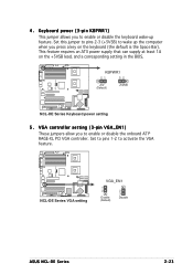
4. KBPWR1 21 32 +5V (Default) +5VSB NCL-DE Series ® NCL-DE Series Keyboard power setting 5 . Set this jumper to pins 2-3 (+5VSB) to enable or disable the keyboard wake-up the computer when you press a key ... requires an ATX power supply that can supply at least 1A on the keyboard (the default is the Space Bar). NCL-DE Series ® NCL-DE Series VGA setting VGA_EN1 1 2 Enable (Default) 2 3 Disable ASUS NCL-DE Series 2-23 VGA controller setting (3-pin VGA_EN1) These jumpers allow you to wake up feature. Set to pins...
4. KBPWR1 21 32 +5V (Default) +5VSB NCL-DE Series ® NCL-DE Series Keyboard power setting 5 . Set this jumper to pins 2-3 (+5VSB) to enable or disable the keyboard wake-up the computer when you press a key ... requires an ATX power supply that can supply at least 1A on the keyboard (the default is the Space Bar). NCL-DE Series ® NCL-DE Series VGA setting VGA_EN1 1 2 Enable (Default) 2 3 Disable ASUS NCL-DE Series 2-23 VGA controller setting (3-pin VGA_EN1) These jumpers allow you to wake up feature. Set to pins...

User Manual
Page 45
...Prepare a floppy disk that contains the latest BIOS for the motherboard (xxxx-xxx.ROM) and the AFUDOS.EXE utility. 2. NCL-DE Series ® NCL-DE Series SCSI setting SCSI_EN1 12 23 Enable (Default) Disable 9 . Insert the floppy disk then turn on the system. ...Turn on the system to pins 1-2. 6. To update the BIOS: 1. Shut down the system. 5. NCL-DE Series ® RECOVERY1 12 23 Normal BIOS Recovery (Default) NCL-DE Series BIOS recovery setting ASUS NCL...
...Prepare a floppy disk that contains the latest BIOS for the motherboard (xxxx-xxx.ROM) and the AFUDOS.EXE utility. 2. NCL-DE Series ® NCL-DE Series SCSI setting SCSI_EN1 12 23 Enable (Default) Disable 9 . Insert the floppy disk then turn on the system. ...Turn on the system to pins 1-2. 6. To update the BIOS: 1. Shut down the system. 5. NCL-DE Series ® RECOVERY1 12 23 Normal BIOS Recovery (Default) NCL-DE Series BIOS recovery setting ASUS NCL...
User Manual
Page 47
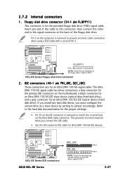
... FDD cable with a covered Pin 5. This prevents incorrect insertion when you must configure the second drive as a slave device by setting its jumper accordingly. NCL-DE Series Floppy disk drive connector 2 . If you install two hard disk drives, you connect the IDE cable. • Use the 80-conductor IDE... cable for an Ultra DMA 100/66 signal cable. NCL-DE Series ® NCL-DE Series IDE connectors ASUS NCL-DE Series SEC_IDE PIN 1 PRI_IDE PIN 1 NOTE: Orient the red markings (usually zigzag) on the IDE ribbon cable to ...
... FDD cable with a covered Pin 5. This prevents incorrect insertion when you must configure the second drive as a slave device by setting its jumper accordingly. NCL-DE Series Floppy disk drive connector 2 . If you install two hard disk drives, you connect the IDE cable. • Use the 80-conductor IDE... cable for an Ultra DMA 100/66 signal cable. NCL-DE Series ® NCL-DE Series IDE connectors ASUS NCL-DE Series SEC_IDE PIN 1 PRI_IDE PIN 1 NOTE: Orient the red markings (usually zigzag) on the IDE ribbon cable to ...
User Manual
Page 49
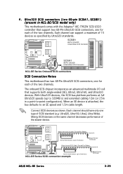
...two channels. With Ultra320 devices, the SCSI bus platform performs at full Ultra320 speeds (up to 15 devices) NCL-DE Series SCSI connection example 68-pin Female Terminator ASUS NCL-DE Series 2-29 When an SE device is attached, the bus defaults to -point configuration). Each channel should... have only one type of the slower device. Ultra320, Ultra160, Ultra2, Ultra-Wide). NCL-DE Series ® 68-pin Internal ...
...two channels. With Ultra320 devices, the SCSI bus platform performs at full Ultra320 speeds (up to 15 devices) NCL-DE Series SCSI connection example 68-pin Female Terminator ASUS NCL-DE Series 2-29 When an SE device is attached, the bus defaults to -point configuration). Each channel should... have only one type of the slower device. Ultra320, Ultra160, Ultra2, Ultra-Wide). NCL-DE Series ® 68-pin Internal ...
User Manual
Page 51
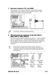
... Series Fan connectors REAR_FAN1 GND +12V Rotation FRNT_FAN1 GND +12V Rotation REAR_FAN2 Rotation +12V GND FRNT_FAN2 GND +12V Rotation ASUS NCL-DE Series 2-31 NCL-DE Series ® COM2 PIN 1 NCL-DE Series Serial port connectors The serial port module is for a serial (COM) port. These are not jumpers! 7 . Do not place jumper caps...
... Series Fan connectors REAR_FAN1 GND +12V Rotation FRNT_FAN1 GND +12V Rotation REAR_FAN2 Rotation +12V GND FRNT_FAN2 GND +12V Rotation ASUS NCL-DE Series 2-31 NCL-DE Series ® COM2 PIN 1 NCL-DE Series Serial port connectors The serial port module is for a serial (COM) port. These are not jumpers! 7 . Do not place jumper caps...
User Manual
Page 53
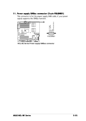
NCL-DE Series ® I2C_7_CLK# I2C_7_DATA# NC GND +3.3V Remote Sense 11. PSUSMB1 NCL-DE Series Power supply SMBus connector ASUS NCL-DE Series 2-33 Power supply SMBus connector (5-pin PSUSMB1) This connector is for the power supply SMB cable, if your power supply supports the SMBus function.
NCL-DE Series ® I2C_7_CLK# I2C_7_DATA# NC GND +3.3V Remote Sense 11. PSUSMB1 NCL-DE Series Power supply SMBus connector ASUS NCL-DE Series 2-33 Power supply SMBus connector (5-pin PSUSMB1) This connector is for the power supply SMB cable, if your power supply supports the SMBus function.
User Manual
Page 55
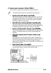
... connector is for the chassis-mounted reset button for the system power LED. POWERLED+ NC POWERLEDMLED+ MLEDNC +5V GND GND SPKROUT NCL-DE Series ® PANEL1 NCL-DE Series System panel connector ASUS NCL-DE Series HDLED+ HDLEDNMIBTN# GND POWERBTN# GND NC RESETBTN# GND 2-35 System panel connector (20-pin PANEL1) This connector supports...
... connector is for the chassis-mounted reset button for the system power LED. POWERLED+ NC POWERLEDMLED+ MLEDNC +5V GND GND SPKROUT NCL-DE Series ® PANEL1 NCL-DE Series System panel connector ASUS NCL-DE Series HDLED+ HDLEDNMIBTN# GND POWERBTN# GND NC RESETBTN# GND 2-35 System panel connector (20-pin PANEL1) This connector supports...
User Manual
Page 58
Chapter summary 3 3.1 Starting up for the first time 3-1 3.2 Turning off the computer 3-2 ASUS NCL-DE Series
Chapter summary 3 3.1 Starting up for the first time 3-1 3.2 Turning off the computer 3-2 ASUS NCL-DE Series


