
User Guide
Page 1
Motherboard N3150I-C N3050I-C
Motherboard N3150I-C N3050I-C
User Guide
Page 3
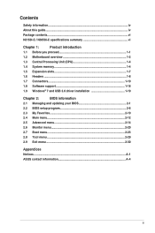
Contents Safety information...iv About this guide...iv Package contents...vi N3150I-C / N3050I-C specifications summary vi Chapter 1: Product introduction 1.1 Before you proceed 1-1 1.2 Motherboard overview 1-2 1.3 Central Processing Unit (CPU 1-4 1.4 System memory 1-4 1.5 Expansion slots 1-7 1.6 Headers...1-8 1.7 Connectors 1-10 1.8 Software support 1-18 1.9 Windows® 7 and USB 3.0... menu...2-12 2.5 Advanced menu 2-14 2.6 Monitor menu 2-20 2.7 Boot menu...2-23 2.8 Tool menu...2-29 2.9 Exit menu...2-30 Appendices Notices...A-1 ASUS contact information A-4 iii
Contents Safety information...iv About this guide...iv Package contents...vi N3150I-C / N3050I-C specifications summary vi Chapter 1: Product introduction 1.1 Before you proceed 1-1 1.2 Motherboard overview 1-2 1.3 Central Processing Unit (CPU 1-4 1.4 System memory 1-4 1.5 Expansion slots 1-7 1.6 Headers...1-8 1.7 Connectors 1-10 1.8 Software support 1-18 1.9 Windows® 7 and USB 3.0... menu...2-12 2.5 Advanced menu 2-14 2.6 Monitor menu 2-20 2.7 Boot menu...2-23 2.8 Tool menu...2-29 2.9 Exit menu...2-30 Appendices Notices...A-1 ASUS contact information A-4 iii
User Guide
Page 4
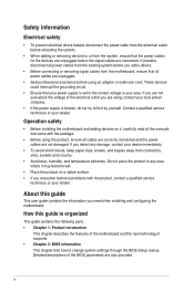
... How this guide This user guide contains the information you add a device. • Before connecting or removing signal cables from the motherboard, ensure that the power cables for the devices are unplugged before the signal cables are not damaged. Contact a qualified service technician or...the features of the BIOS parameters are using an adapter or extension cord. If you are also provided. Detailed descriptions of the motherboard and the new technology it by yourself. Safety information Electrical safety • To prevent electrical shock hazard, disconnect the power ...
... How this guide This user guide contains the information you add a device. • Before connecting or removing signal cables from the motherboard, ensure that the power cables for the devices are unplugged before the signal cables are not damaged. Contact a qualified service technician or...the features of the BIOS parameters are using an adapter or extension cord. If you are also provided. Detailed descriptions of the motherboard and the new technology it by yourself. Safety information Electrical safety • To prevent electrical shock hazard, disconnect the power ...
User Guide
Page 6
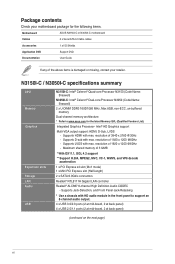
... Memory Graphics Expansion slots Storage LAN Audio USB N3150I-C: Intel® Celeron® Quad-core Processor N3150 (Code Name: Braswell) N3050I-C: Intel® Celeron® Dual-core Processor N3050 (Code Name: Braswell) 2 x U-DIMM DDR3 1600/1066 MHz, Max ... Vendors List). resolution of 1920 x 1200 @60Hz - Supports LVDS with HD audio module in the front panel to www.asus.com for the following items. Motherboard ASUS N3150I-C or N3050I-C motherboard Cables 2 x Serial ATA 6.0 Gb/s cables Accessories 1 x I/O Shields Application DVD Support DVD Documentation User Guide If any...
... Memory Graphics Expansion slots Storage LAN Audio USB N3150I-C: Intel® Celeron® Quad-core Processor N3150 (Code Name: Braswell) N3050I-C: Intel® Celeron® Dual-core Processor N3050 (Code Name: Braswell) 2 x U-DIMM DDR3 1600/1066 MHz, Max ... Vendors List). resolution of 1920 x 1200 @60Hz - Supports LVDS with HD audio module in the front panel to www.asus.com for the following items. Motherboard ASUS N3150I-C or N3050I-C motherboard Cables 2 x Serial ATA 6.0 Gb/s cables Accessories 1 x I/O Shields Application DVD Support DVD Documentation User Guide If any...

User Guide
Page 9
ASUS N3150I-C / N3050I-C 1-1 Failure to do so may cause severe damage to avoid touching the ICs on them. • Whenever you...is detached from the power supply. Product introduction 1 1.1 Before you proceed Take note of the following precautions before you install motherboard components or change any motherboard settings. • Unplug the power cord from the wall socket before touching any component. • Before handling components, ...supply case, to avoid damaging them due to static electricity. • Hold components by the edges to the motherboard, peripherals, or components.
ASUS N3150I-C / N3050I-C 1-1 Failure to do so may cause severe damage to avoid touching the ICs on them. • Whenever you...is detached from the power supply. Product introduction 1 1.1 Before you proceed Take note of the following precautions before you install motherboard components or change any motherboard settings. • Unplug the power cord from the wall socket before touching any component. • Before handling components, ...supply case, to avoid damaging them due to static electricity. • Hold components by the edges to the motherboard, peripherals, or components.

User Guide
Page 10
... it into the holes indicated by circles to secure the motherboard to the chassis. Ensure that you unplug the power cord before installing or removing the motherboard. Do not overtighten the screws! Place this side towards the rear of the chassis N3150I-C N3050I-C 1-2 Chapter 1: Product introduction Doing so can cause you physical injury...
... it into the holes indicated by circles to secure the motherboard to the chassis. Ensure that you unplug the power cord before installing or removing the motherboard. Do not overtighten the screws! Place this side towards the rear of the chassis N3150I-C N3050I-C 1-2 Chapter 1: Product introduction Doing so can cause you physical injury...
User Guide
Page 11
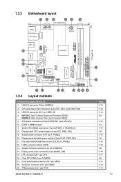
...(40-pin LVDS) 13. LPT connector (26-1 pin LPT) 16. Display panel VCC power selector (3-pin VCC_PWR_SEL) 9. 1.2.3 Motherboard layout 1 2 3 45 6 17.0cm(6.7in) KBMS CPU_FAN CHA_FAN LAN_USBE12 ATX12V LANGuard USB3_12 USBE34 USB3_34 19 ASM 1442K Intel®...COM2) 19. USB 2.0 connector (10-pin USBE34) 2. USB 3.0 connector (20-1 pin USB3_34) 4. TPM connector (14-1 pin TPM) ASUS N3150I-C / N3050I-C Mini PCIe SATA6G_1 SATA6G_2 N3150I-C N3050I-C DDR3_DIMM_A1 (64bit, 240-pin module) DDR3_DIMM_B1 (64bit, 240-pin module) EATX_PWR 17.0cm(6.7in) 5 7 Page 1-14 1-12 1-14...
...(40-pin LVDS) 13. LPT connector (26-1 pin LPT) 16. Display panel VCC power selector (3-pin VCC_PWR_SEL) 9. 1.2.3 Motherboard layout 1 2 3 45 6 17.0cm(6.7in) KBMS CPU_FAN CHA_FAN LAN_USBE12 ATX12V LANGuard USB3_12 USBE34 USB3_34 19 ASM 1442K Intel®...COM2) 19. USB 2.0 connector (10-pin USBE34) 2. USB 3.0 connector (20-1 pin USB3_34) 4. TPM connector (14-1 pin TPM) ASUS N3150I-C / N3050I-C Mini PCIe SATA6G_1 SATA6G_2 N3150I-C N3050I-C DDR3_DIMM_A1 (64bit, 240-pin module) DDR3_DIMM_B1 (64bit, 240-pin module) EATX_PWR 17.0cm(6.7in) 5 7 Page 1-14 1-12 1-14...

User Guide
Page 12
..., install it to DIMM_A1 slot. 1-4 Chapter 1: Product introduction N3150I-C N3050I-C Intel SOC N3150I-C / N3050I-C CPU N3150I-C with two Double Data Rate 3 (DDR3) U-DIMM sockets. N3050I-C with Intel SOC N3050. 1.4 System memory 1.4.1 Overview This motherboard comes with Intel SOC N3150. 1.3 Central Processing Unit (CPU) The motherboard comes with an onboard Intel® Celeron Quad-core/ Dual...
..., install it to DIMM_A1 slot. 1-4 Chapter 1: Product introduction N3150I-C N3050I-C Intel SOC N3150I-C / N3050I-C CPU N3150I-C with two Double Data Rate 3 (DDR3) U-DIMM sockets. N3050I-C with Intel SOC N3050. 1.4 System memory 1.4.1 Overview This motherboard comes with Intel SOC N3150. 1.3 Central Processing Unit (CPU) The motherboard comes with an onboard Intel® Celeron Quad-core/ Dual...
User Guide
Page 13
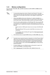
... motherboard, the actual usable memory for the latest Memory QVL (Qualified Vendors List). For optimal compatibility, we recommend that you want to install 4GB or more efficient memory cooling system to support a full memory load (2 DIMMs) or overclocking condition. • Refer to www.asus....we recommend that you do any of the same version or date code (D/C) from a memory module. Check with the same CAS latency. ASUS N3150I-C / N3050I-C 1-5 Install a maximum of the lower-sized channel for overclocking may install varying memory sizes in Channel A and Channel B. Under the ...
... motherboard, the actual usable memory for the latest Memory QVL (Qualified Vendors List). For optimal compatibility, we recommend that you want to install 4GB or more efficient memory cooling system to support a full memory load (2 DIMMs) or overclocking condition. • Refer to www.asus....we recommend that you do any of the same version or date code (D/C) from a memory module. Check with the same CAS latency. ASUS N3150I-C / N3050I-C 1-5 Install a maximum of the lower-sized channel for overclocking may install varying memory sizes in Channel A and Channel B. Under the ...
User Guide
Page 15
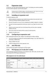
...an expansion card: 1. Secure the card to install expansion cards. Keep the screw for later use . Turn on the slot. 5. See Chapter 2 for this motherboard Component PCIe x4 Realtek 8111H LAN controller SATA controller HD Audio XHCI controller A B C D E F G H shared - - - - - - - ... press firmly until the card is already installed in a chassis). 3. shared - - - - - - - - - - ASUS N3150I-C / N3050I-C 1-7 Remove the bracket opposite the slot that they support. Replace the system cover. 1.5.2 Configuring an expansion card After installing the ...
...an expansion card: 1. Secure the card to install expansion cards. Keep the screw for later use . Turn on the slot. 5. See Chapter 2 for this motherboard Component PCIe x4 Realtek 8111H LAN controller SATA controller HD Audio XHCI controller A B C D E F G H shared - - - - - - - ... press firmly until the card is already installed in a chassis). 3. shared - - - - - - - - - - ASUS N3150I-C / N3050I-C 1-7 Remove the bracket opposite the slot that they support. Replace the system cover. 1.5.2 Configuring an expansion card After installing the ...
User Guide
Page 19
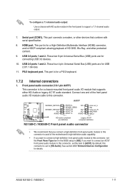
... avail of the front panel audio I /O module that supports either HD Audio or legacy AC`97 audio standard. By default, this connector. ASUS N3150I-C / N3050I-C 1-11 This port connects a modem, or other protected content. 9. USB 3.0 ports 1 and 2. To configure a 7.1-channel audio output:... Use a chassis with serial specification. 8. HDMI port. PS/2 keyboard port. Connect one end of the motherboard's high-definition audio capability. • If ...
... avail of the front panel audio I /O module that supports either HD Audio or legacy AC`97 audio standard. By default, this connector. ASUS N3150I-C / N3050I-C 1-11 This port connects a modem, or other protected content. 9. USB 3.0 ports 1 and 2. To configure a 7.1-channel audio output:... Use a chassis with serial specification. 8. HDMI port. PS/2 keyboard port. Connect one end of the motherboard's high-definition audio capability. • If ...

User Guide
Page 20
... GND 1-12 Chapter 1: Product introduction 2. CPU_FAN CHA_FAN N3150I-C / N3050I-C Fan connectors Do not forget to connect the fan cables to the fan connectors on the fan connectors! Do not place jumper caps on the motherboard, ensuring that the black wire of each cable matches the ground pin... of the system chassis. Insufficient air flow inside the system may damage the motherboard components. Serial port connector (10-1 pin COM1) This connector is purchased separately. 3. Connect the serial port module cable to this connector...
... GND 1-12 Chapter 1: Product introduction 2. CPU_FAN CHA_FAN N3150I-C / N3050I-C Fan connectors Do not forget to connect the fan cables to the fan connectors on the fan connectors! Do not place jumper caps on the motherboard, ensuring that the black wire of each cable matches the ground pin... of the system chassis. Insufficient air flow inside the system may damage the motherboard components. Serial port connector (10-1 pin COM1) This connector is purchased separately. 3. Connect the serial port module cable to this connector...

User Guide
Page 22
... USB module cable is purchased separately. 1-14 Chapter 1: Product introduction N3150I-C N3050I-C USBE34 NC GND USB_P3+ USB_P3USB+5V GND USB_P4+ USB_P4USB+5V PIN 1 N3150I-C / N3050I-C USB2.0 connector Never connect a 1394 cable to connect a USB 3.0 module...USB connector. Doing so will damage the motherboard! USB3_34 N3150I-C N3050I-C USB3+5V IntA_P2_SSRXIntA_P2_SSRX+ GND IntA_P2_SSTXIntA_P2_SSTX+ GND IntA_P2_DIntA_P2_D+ PIN 1 USB3+5V IntA_P1_SSRXIntA_P1_SSRX+ GND IntA_P1_SSTXIntA_P1_SSTX+ GND IntA_P1_DIntA_P1_D+ GND N3150I-C / N3050I-C USB3.0 connector The USB 3.0 module is...
... USB module cable is purchased separately. 1-14 Chapter 1: Product introduction N3150I-C N3050I-C USBE34 NC GND USB_P3+ USB_P3USB+5V GND USB_P4+ USB_P4USB+5V PIN 1 N3150I-C / N3050I-C USB2.0 connector Never connect a 1394 cable to connect a USB 3.0 module...USB connector. Doing so will damage the motherboard! USB3_34 N3150I-C N3050I-C USB3+5V IntA_P2_SSRXIntA_P2_SSRX+ GND IntA_P2_SSTXIntA_P2_SSTX+ GND IntA_P2_DIntA_P2_D+ PIN 1 USB3+5V IntA_P1_SSRXIntA_P1_SSRX+ GND IntA_P1_SSTXIntA_P1_SSTX+ GND IntA_P1_DIntA_P1_D+ GND N3150I-C / N3050I-C USB3.0 connector The USB 3.0 module is...
User Guide
Page 26
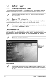
... from the BIN folder. Click Drivers, Utilities, Manual, and Contact tabs to maximize the features of ASUS motherboard. Double-click the ASSETUP.EXE to change at www.asus.com for updates. If Autorun is NOT enabled in your computer, browse the contents of the Support... of your OS documentation for reference only. Visit the ASUS website at any time without notice. 1.8 Software support 1.8.1 Installing an operating system This motherboard supports Windows® 8.1 64-bit and Windows® 7 64-bit. Motherboard settings and hardware options vary. Always install the latest ...
... from the BIN folder. Click Drivers, Utilities, Manual, and Contact tabs to maximize the features of ASUS motherboard. Double-click the ASSETUP.EXE to change at www.asus.com for updates. If Autorun is NOT enabled in your computer, browse the contents of the Support... of your OS documentation for reference only. Visit the ASUS website at any time without notice. 1.8 Software support 1.8.1 Installing an operating system This motherboard supports Windows® 8.1 64-bit and Windows® 7 64-bit. Motherboard settings and hardware options vary. Always install the latest ...
User Guide
Page 31
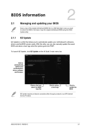
... your BIOS Save a copy of the original motherboard BIOS file to a USB flash disk in case you need to automatically update your motherboard's softwares, drivers and the BIOS version easily. Copy the original motherboard BIOS using the ASUS Update utility. 2.1.1 EZ Update EZ Update is... a utility that allows you can also manually update the saved BIOS and select a boot logo when the system goes into POST. ASUS N3150I-C / N3050I...
... your BIOS Save a copy of the original motherboard BIOS file to a USB flash disk in case you need to automatically update your motherboard's softwares, drivers and the BIOS version easily. Copy the original motherboard BIOS using the ASUS Update utility. 2.1.1 EZ Update EZ Update is... a utility that allows you can also manually update the saved BIOS and select a boot logo when the system goes into POST. ASUS N3150I-C / N3050I...
User Guide
Page 33
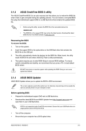
... DVD optical drive. Download the latest BIOS file from http://support.asus.com and save them in the support DVD may not be the latest version. Doing so can restore a corrupted BIOS file using the motherboard support DVD or a USB flash drive that your computer screen.... to the USB port. 3. Before updating BIOS • Prepare the motherboard support DVD and a USB flash drive. • Download the latest BIOS file and BIOS Updater from the ASUS website at www.asus.com. ASUS N3150I-C / N3050I-C 2-3 The utility automatically checks the devices for reference only and may...
... DVD optical drive. Download the latest BIOS file from http://support.asus.com and save them in the support DVD may not be the latest version. Doing so can restore a corrupted BIOS file using the motherboard support DVD or a USB flash drive that your computer screen.... to the USB port. 3. Before updating BIOS • Prepare the motherboard support DVD and a USB flash drive. • Download the latest BIOS file and BIOS Updater from the ASUS website at www.asus.com. ASUS N3150I-C / N3050I-C 2-3 The utility automatically checks the devices for reference only and may...
User Guide
Page 36
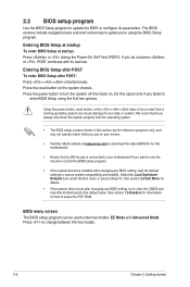
...unstable after changing any BIOS setting, try to clear the CMOS and reset the motherboard to enter BIOS Setup using the BIOS Setup program. Entering BIOS Setup at startup To enter BIOS Setup at www.asus.com to download the latest BIOS file for information on the system chassis. Select... the Load Optimized Defaults item under two modes: EZ Mode and Advanced Mode. Do this option only if you in this motherboard. • Ensure that a USB mouse...
...unstable after changing any BIOS setting, try to clear the CMOS and reset the motherboard to enter BIOS Setup using the BIOS Setup program. Entering BIOS Setup at startup To enter BIOS Setup at www.asus.com to download the latest BIOS file for information on the system chassis. Select... the Load Optimized Defaults item under two modes: EZ Mode and Advanced Mode. Do this option only if you in this motherboard. • Ensure that a USB mouse...

User Guide
Page 37
... the BIOS setup program can be changed. To access the Advanced Mode, click Advanced Mode(F7) or press . Displays the CPU/motherboard temperature, CPU voltage output, CPU/chassis fan speed, and SATA information Selects the display language of the basic system information, and allows... you installed to select the display language, system performance mode, fan profile and boot device priority. ASUS N3150I-C / N3050I-C 2-7 The EZ Mode provides you an overview of the BIOS setup program Loads optimized default settings Shows the bootable devices Saves...
... the BIOS setup program can be changed. To access the Advanced Mode, click Advanced Mode(F7) or press . Displays the CPU/motherboard temperature, CPU voltage output, CPU/chassis fan speed, and SATA information Selects the display language of the basic system information, and allows... you installed to select the display language, system performance mode, fan profile and boot device priority. ASUS N3150I-C / N3050I-C 2-7 The EZ Mode provides you an overview of the BIOS setup program Loads optimized default settings Shows the bootable devices Saves...

User Guide
Page 38
To access the EZ Mode, click EzMode(F7) or press . 2.2.2 Advanced Mode The Advanced Mode provides advanced options for the detailed configurations. Quick Note MyFavorite Language Menu bar Hot Keys Sub-menu item Menu items General help Configuration fields Scroll bar Last modified settings Goes back to configure the BIOS settings. The figure below shows an example of the Advanced Mode. Refer to the following sections for experienced end-users to EZ Mode Displays the CPU/motherboard temperature, CPU and memory voltage output 2-8 Chapter 2: Getting started
To access the EZ Mode, click EzMode(F7) or press . 2.2.2 Advanced Mode The Advanced Mode provides advanced options for the detailed configurations. Quick Note MyFavorite Language Menu bar Hot Keys Sub-menu item Menu items General help Configuration fields Scroll bar Last modified settings Goes back to configure the BIOS settings. The figure below shows an example of the Advanced Mode. Refer to the following sections for experienced end-users to EZ Mode Displays the CPU/motherboard temperature, CPU and memory voltage output 2-8 Chapter 2: Getting started

User Guide
Page 48
... sub-items in this item to set the parallel port configuration. 2-18 Chapter 2: Getting started USB Single Port Control This item allows you to section 1.2.3 Motherboard layout for the location of the Realtek LAN controller. Configuration options: [On] [Off] Change Settings [IO=3F8h; Refer to enable or disable the individual USB...
... sub-items in this item to set the parallel port configuration. 2-18 Chapter 2: Getting started USB Single Port Control This item allows you to section 1.2.3 Motherboard layout for the location of the Realtek LAN controller. Configuration options: [On] [Off] Change Settings [IO=3F8h; Refer to enable or disable the individual USB...


