User Manual
Page 1
TABLE OF CONTENTS IMPORTANT INFORMATION 1 PRECAUTIONS 2 SPECIAL NOTES 3 TAKE CARE OF THE MONITOR 3 BEFORE YOU OPERATE THE MONITOR 4 FEATURES 4 PACKING LIST 4 INSTALLATION INSTRUCTIONS 5 ADJUSTING THE VIEWING ANGLE 7 OPERATING INSTRUCTIONS 8 GENERAL INSTRUCTIONS 8 HOW TO RECONFIGURE 9 OSD MENU TABLE 10 PLUG AND PLAY 12 TROUBLESHOOTING (FAQ 13 ERROR MESSAGE & POSSIBLE SOLUTION 14 APPENDIX 15 SPECIFICATIONS 15 PRESET TIMING TABLE 16 CONNECTOR PIN ASSIGNMENT 17
TABLE OF CONTENTS IMPORTANT INFORMATION 1 PRECAUTIONS 2 SPECIAL NOTES 3 TAKE CARE OF THE MONITOR 3 BEFORE YOU OPERATE THE MONITOR 4 FEATURES 4 PACKING LIST 4 INSTALLATION INSTRUCTIONS 5 ADJUSTING THE VIEWING ANGLE 7 OPERATING INSTRUCTIONS 8 GENERAL INSTRUCTIONS 8 HOW TO RECONFIGURE 9 OSD MENU TABLE 10 PLUG AND PLAY 12 TROUBLESHOOTING (FAQ 13 ERROR MESSAGE & POSSIBLE SOLUTION 14 APPENDIX 15 SPECIFICATIONS 15 PRESET TIMING TABLE 16 CONNECTOR PIN ASSIGNMENT 17
User Manual
Page 2
... can radiate radio frequency energy, and if not installed and used in a particular installation. Increase the separation between the equipment and receiver. 3. It is not responsible for future reference. Refer servicing to rain or moisture. Reorient or relocate the receiving antenna. 2. Shielded interface cables and AC power cord, if any radio or TV interference caused by turning the equipment...
... can radiate radio frequency energy, and if not installed and used in a particular installation. Increase the separation between the equipment and receiver. 3. It is not responsible for future reference. Refer servicing to rain or moisture. Reorient or relocate the receiving antenna. 2. Shielded interface cables and AC power cord, if any radio or TV interference caused by turning the equipment...
User Manual
Page 3
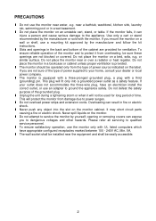
... power outlet as a safety feature. It may short circuit parts causing a fire or electric shock. l Do not attempt to service the monitor by the manufacturer and follow the kit instructions. opening or removing covers can injure a person and cause serious damage to the appliance. If the monitor falls, it will fit only into the slot on a wall or shelf, use the monitor...
... power outlet as a safety feature. It may short circuit parts causing a fire or electric shock. l Do not attempt to service the monitor by the manufacturer and follow the kit instructions. opening or removing covers can injure a person and cause serious damage to the appliance. If the monitor falls, it will fit only into the slot on a wall or shelf, use the monitor...

User Manual
Page 4
... screen may remain after switching the image, when the same image is originally packed in the factory. • To maintain cleanness of the fluorescent light, the screen may flicker during initial use. SPECIAL NOTES The following symptoms are normal with the monitor and do not indicate a problem. • Due to replace parts. TAKE CARE OF THE MONITOR • Do not install the monitor in a location near heat sources...
... screen may remain after switching the image, when the same image is originally packed in the factory. • To maintain cleanness of the fluorescent light, the screen may flicker during initial use. SPECIAL NOTES The following symptoms are normal with the monitor and do not indicate a problem. • Due to replace parts. TAKE CARE OF THE MONITOR • Do not install the monitor in a location near heat sources...

User Manual
Page 5
... Selection for Users' Preference. • Microsoft Windows 95/98/2000/XP Compliance • VESA Display Data Channel (DDC)1/2B Compliance • VESA Wall Mount Compliance (100x100mm). • EPA ENERGY STAR® and Ergonomic Design. • Cabel Binder and Compact Case Design for Space Saving. • Both VGA and DVI-D Inputs. (for MM17T only) • 1.2Wx2 Stereo Speakers / Earphone Jack. (for MM17T only) 4 Power Cord 5. LCD Monitor 2.
... Selection for Users' Preference. • Microsoft Windows 95/98/2000/XP Compliance • VESA Display Data Channel (DDC)1/2B Compliance • VESA Wall Mount Compliance (100x100mm). • EPA ENERGY STAR® and Ergonomic Design. • Cabel Binder and Compact Case Design for Space Saving. • Both VGA and DVI-D Inputs. (for MM17T only) • 1.2Wx2 Stereo Speakers / Earphone Jack. (for MM17T only) 4 Power Cord 5. LCD Monitor 2.
User Manual
Page 6
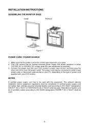
... according to IEC 60227 (designation H05VV-F 3G 0.75mm2 or H05VVH2-F2 3G 0.75mm2) shall be used . The power cord may be used with your PC, depending on your LCD monitor. Connect the power cord into a 3-pin AC power outlet. Alternative a flexible cord be considered. Make sure that allows operation in your LCD monitor's power input socket, and then plug the other end into your area. 2. INSTALLATION INSTRUCTIONS ASSEMBLING THE MONITOR BASE Install Remove Figure 1 POWER CORD / POWER SOURCE 1.
... according to IEC 60227 (designation H05VV-F 3G 0.75mm2 or H05VVH2-F2 3G 0.75mm2) shall be used . The power cord may be used with your PC, depending on your LCD monitor. Connect the power cord into a 3-pin AC power outlet. Alternative a flexible cord be considered. Make sure that allows operation in your LCD monitor's power input socket, and then plug the other end into your area. 2. INSTALLATION INSTRUCTIONS ASSEMBLING THE MONITOR BASE Install Remove Figure 1 POWER CORD / POWER SOURCE 1.
User Manual
Page 7
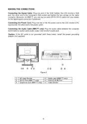
... (or audio) card's audio output and monitor's audio jack. AC Input Socket 3. Audio Jack (MM17T only) 4. Connecting the Power Cord: Plug one end of the AC-power cord to the LCD monitor's AC input socket, the other end to the power outlet. VGA (D-SUB) Port 6. Figure 2 1. Caution: If the AC outlet is not grounded (with three holes), install the proper grounding adapter (not supplied). MAKING THE CONNECTIONS Connecting the Signal Cable: Plug one end of the VGA Cableto the LCD monitor's VGA port...
... (or audio) card's audio output and monitor's audio jack. AC Input Socket 3. Audio Jack (MM17T only) 4. Connecting the Power Cord: Plug one end of the AC-power cord to the LCD monitor's AC input socket, the other end to the power outlet. VGA (D-SUB) Port 6. Figure 2 1. Caution: If the AC outlet is not grounded (with three holes), install the proper grounding adapter (not supplied). MAKING THE CONNECTIONS Connecting the Signal Cable: Plug one end of the VGA Cableto the LCD monitor's VGA port...
User Manual
Page 8
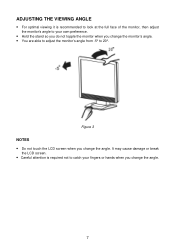
It may cause damage or break the LCD screen. • Careful attention is recommended to look at the full face of the monitor, then adjust the monitor's angle to 20°. ADJUSTING THE VIEWING ANGLE • For optimal viewing it is required not to catch your fingers or hands when you change the monitor's angle. • You are able to adjust the monitor's angle from -5° to your own preference. • Hold the stand so you do not topple the monitor when you change the angle. Figure 3 NOTES • Do not touch the LCD screen when you change the angle. 7
It may cause damage or break the LCD screen. • Careful attention is recommended to look at the full face of the monitor, then adjust the monitor's angle to 20°. ADJUSTING THE VIEWING ANGLE • For optimal viewing it is required not to catch your fingers or hands when you change the monitor's angle. • You are able to adjust the monitor's angle from -5° to your own preference. • Hold the stand so you do not topple the monitor when you change the angle. Figure 3 NOTES • Do not touch the LCD screen when you change the angle. 7
User Manual
Page 9
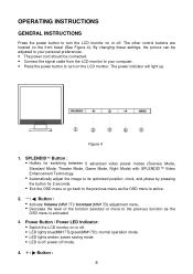
...; LED lights blue(MM17T)/green(MM17D): normal operation mode. • LED lights amber: power saving mode. • LED is activated. 3. OPERATING INSTRUCTIONS GENERAL INSTRUCTIONS Press the power button to turn on the LCD monitor. The power indicator will light up. By changing these settings, the picture can be adjusted to your personal preferences. • The power cord should be connected. • Connect the signal cable from the LCD monitor to your computer. • Press the power button to the previous function as the OSD menu is...
...; LED lights blue(MM17T)/green(MM17D): normal operation mode. • LED lights amber: power saving mode. • LED is activated. 3. OPERATING INSTRUCTIONS GENERAL INSTRUCTIONS Press the power button to turn on the LCD monitor. The power indicator will light up. By changing these settings, the picture can be adjusted to your personal preferences. • The power cord should be connected. • Connect the signal cable from the LCD monitor to your computer. • Press the power button to the previous function as the OSD menu is...

User Manual
Page 10
... or again to navigate through the functions. Once the desired function is highlighted, press MENU-button to activate it . Press the MENU-button to activate the OSD main menu (Figure 5). 2. Menu Button : • Activate the OSD (On-Screen Display) main menu. • Enter/select the icon(function) highlighted as the OSD menu is activated. • Activate Brightness adjustment menu. • Increase the level of the selected function. 4.
... or again to navigate through the functions. Once the desired function is highlighted, press MENU-button to activate it . Press the MENU-button to activate the OSD main menu (Figure 5). 2. Menu Button : • Activate the OSD (On-Screen Display) main menu. • Enter/select the icon(function) highlighted as the OSD menu is activated. • Activate Brightness adjustment menu. • Increase the level of the selected function. 4.
User Manual
Page 11
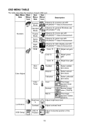
... dark-display use with SPLENDID™ Video Enhancement Color R Adjust red gain Color G Color B Adjust green gain Adjust blue gain Color Adjust Luminance Skin Tone Color Temp Brightnes s Contrast Reddish Select reddish skin stone Natural Select natural skin stone Yellowish Select yellowish skin stone Cool Normal The image appears bluer. (9300°K) Normal image color. (7500°K) Warm The image appears redder. (6500°K) Adjust brightness level Adjust contrast level OSD Setup OSD HPosition Adjust horizontal position of the OSD 10
... dark-display use with SPLENDID™ Video Enhancement Color R Adjust red gain Color G Color B Adjust green gain Adjust blue gain Color Adjust Luminance Skin Tone Color Temp Brightnes s Contrast Reddish Select reddish skin stone Natural Select natural skin stone Yellowish Select yellowish skin stone Cool Normal The image appears bluer. (9300°K) Normal image color. (7500°K) Warm The image appears redder. (6500°K) Adjust brightness level Adjust contrast level OSD Setup OSD HPosition Adjust horizontal position of the OSD 10
User Manual
Page 12
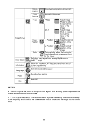
... of the image Clock Adjust image Clock to reduce Vertical-line noise of the image Image H-Position Adjust horizontal Position position of the image V-Position Adjust vertical position of the image Auto Automatically adjust the horizontal /vertical positions, phase and clock of the image Select an input signal from analog/digital source (MM17T only) Show the resolution,H/V frequency and input port of current input timing Select the desired language Recall default setting Exit OSD NOTES • PHASE adjusts the phase of pixels scanned by one horizontal sweep. If...
... of the image Clock Adjust image Clock to reduce Vertical-line noise of the image Image H-Position Adjust horizontal Position position of the image V-Position Adjust vertical position of the image Auto Automatically adjust the horizontal /vertical positions, phase and clock of the image Select an input signal from analog/digital source (MM17T only) Show the resolution,H/V frequency and input port of current input timing Select the desired language Recall default setting Exit OSD NOTES • PHASE adjusts the phase of pixels scanned by one horizontal sweep. If...
User Manual
Page 13
After the video input signal is restored, full power is restored and the display is similar to an OFF mode. The voltage rating for the Northern American region is the wallet plug with a grounding type attachment plug, rated 10A, 250V, CEE-22 male configuration. Supplied with VESA DDC2B capabilities according to the VESA DDC STANDARD. Please note that power supply cord needs to use a cord set by the Video Electronics Standards Association...
After the video input signal is restored, full power is restored and the display is similar to an OFF mode. The voltage rating for the Northern American region is the wallet plug with a grounding type attachment plug, rated 10A, 250V, CEE-22 male configuration. Supplied with VESA DDC2B capabilities according to the VESA DDC STANDARD. Please note that power supply cord needs to use a cord set by the Video Electronics Standards Association...
User Manual
Page 14
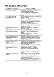
... the Power Cord is properly installed and activated. 13 l Ensure the computer sound card driver is properly connected the monitor and the power outlet. l Adjust the Contrast and Brightness settings via OSD. l Adjust the Phase and Clock settings via OSD. Possible Solution l Press the Power Button to check if the computer is properly connected the monitor and the computer l Adjust the volume settings of the pins are in the ON mode. l Adjust the H-Position or V-Position settings via OSD l Make sure the Signal Cable...
... the Power Cord is properly installed and activated. 13 l Ensure the computer sound card driver is properly connected the monitor and the power outlet. l Adjust the Contrast and Brightness settings via OSD. l Adjust the Phase and Clock settings via OSD. Possible Solution l Press the Power Button to check if the computer is properly connected the monitor and the computer l Adjust the volume settings of the pins are in the ON mode. l Adjust the H-Position or V-Position settings via OSD l Make sure the Signal Cable...
User Manual
Page 15
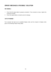
ERROR MESSAGE & POSSIBLE SOLUTION NO SIGNAL︰ 1. Check the signal-cable's connection pins for damage. OUT OF RANGE︰ Your computer has been set to unsuitable display mode ,set the computer to display mode given in the following Preset Timing Table. 14 Check that the signal-cable is properly connected , If the connector is loose, tighten the connector's screws. 2.
ERROR MESSAGE & POSSIBLE SOLUTION NO SIGNAL︰ 1. Check the signal-cable's connection pins for damage. OUT OF RANGE︰ Your computer has been set to unsuitable display mode ,set the computer to display mode given in the following Preset Timing Table. 14 Check that the signal-cable is properly connected , If the connector is loose, tighten the connector's screws. 2.
User Manual
Page 16
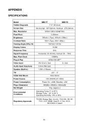
... SPECIFICATIONS Model Visible Diagonals Screen Size Max. Resolution Pixel Pitch Brightness Contrast Ratio Viewing Angle (CR≧10) Display Colors Response Time Signal Frequency Max. Dimension Net Weight Environmental Conditions MM17T MM17D 17.0" (43.2cm) Horizontal : 337.92mm, Vertical : 270.34mm SXGA 1280x1024@75Hz 0.264mm 300cd/㎡ (Typ.), 400cd/㎡ (Max.) 500:1 (Typ.), 600:1 (Max.) 150°(H)/ 130°(V) 16.2M 8ms Horizontal: 30~80 kHz, Vertical...
... SPECIFICATIONS Model Visible Diagonals Screen Size Max. Resolution Pixel Pitch Brightness Contrast Ratio Viewing Angle (CR≧10) Display Colors Response Time Signal Frequency Max. Dimension Net Weight Environmental Conditions MM17T MM17D 17.0" (43.2cm) Horizontal : 337.92mm, Vertical : 270.34mm SXGA 1280x1024@75Hz 0.264mm 300cd/㎡ (Typ.), 400cd/㎡ (Max.) 500:1 (Typ.), 600:1 (Max.) 150°(H)/ 130°(V) 16.2M 8ms Horizontal: 30~80 kHz, Vertical...

User Manual
Page 18
... 3- 24. DESCRIPTION Red Green Blue TXD Ground R-Ground G-Ground B-Ground 9. +5V 10. TMDS Data 3+ 2. TMDS Data 1/3 23. RXD 12. DESCRIPTION PI N NO. Ground(for+5V) Shield 4. TMDS Data 0- 6. TMDS Data 0+ 7. DDC Data 19. Detect Cable 11. V-Sync 15. DESCRIPTION 1. TMDS Clock Shield 11. H-Sync 14. Pin Color Display Signal Cable(MM17T only) PIN NO. TMDS Data 2+ 14. +5V Power 3. N.C. 20. TMDS...
... 3- 24. DESCRIPTION Red Green Blue TXD Ground R-Ground G-Ground B-Ground 9. +5V 10. TMDS Data 3+ 2. TMDS Data 1/3 23. RXD 12. DESCRIPTION PI N NO. Ground(for+5V) Shield 4. TMDS Data 0- 6. TMDS Data 0+ 7. DDC Data 19. Detect Cable 11. V-Sync 15. DESCRIPTION 1. TMDS Clock Shield 11. H-Sync 14. Pin Color Display Signal Cable(MM17T only) PIN NO. TMDS Data 2+ 14. +5V Power 3. N.C. 20. TMDS...


