MES User Manual
Page 4
... 49 4 ASUS MES User's Manual CONTENTS 1. HARDWARE SETUP 14 3.1 Motherboard Layout 14 3.2 Layout Contents 15 3.3 Hardware Setup Procedure 17 3.4 Motherboard Settings 17 3.5 System Memory (DIMM 24 3.5.1 VGA Shared Memory with DIMM 24 3.5.2 General DIMM Notes 24 3.5.3 DIMM Memory Installation 25 3.6 Central Processing Unit (CPU 26 3.7 Expansion Cards 27 3.7.1 Expansion Card Installation Procedure 27 3.7.2 Assigning IRQs for Expansion Cards 27 3.7.3 Assigning DMA Channels for ISA Cards 28 3.7.4 ISA Cards and Hardware Monitor 28 3.8 External Connectors 29 3.9 Power Connection...
... 49 4 ASUS MES User's Manual CONTENTS 1. HARDWARE SETUP 14 3.1 Motherboard Layout 14 3.2 Layout Contents 15 3.3 Hardware Setup Procedure 17 3.4 Motherboard Settings 17 3.5 System Memory (DIMM 24 3.5.1 VGA Shared Memory with DIMM 24 3.5.2 General DIMM Notes 24 3.5.3 DIMM Memory Installation 25 3.6 Central Processing Unit (CPU 26 3.7 Expansion Cards 27 3.7.1 Expansion Card Installation Procedure 27 3.7.2 Assigning IRQs for Expansion Cards 27 3.7.3 Assigning DMA Channels for ISA Cards 28 3.7.4 ISA Cards and Hardware Monitor 28 3.8 External Connectors 29 3.9 Power Connection...
MES User Manual
Page 7
...IDE drives (1) Ribbon cable for master and slave UltraDMA/33 & UltraDMA/66 IDE drives (1) Ribbon cable for (1) 5.25" and (2) 3.5" floppy drives (1) Serial COM2 cable connector set (1) Bag of spare jumper caps (1) Support CD with drivers and utilities (1) This Motherboard User's Manual Connector set for LCD (with LCD chip onboard) Connector set for TV Out (with TV Out chip onboard) Connector set for audio input/output and game/MIDI port (with audio chip onboard) ASUS IrDA-compliant infrared module (optional) ASUS PCI-L101 Wake-On-LAN 10/100 Fast Ethernet Card (optional) ASUS MES User's Manual...
...IDE drives (1) Ribbon cable for master and slave UltraDMA/33 & UltraDMA/66 IDE drives (1) Ribbon cable for (1) 5.25" and (2) 3.5" floppy drives (1) Serial COM2 cable connector set (1) Bag of spare jumper caps (1) Support CD with drivers and utilities (1) This Motherboard User's Manual Connector set for LCD (with LCD chip onboard) Connector set for TV Out (with TV Out chip onboard) Connector set for audio input/output and game/MIDI port (with audio chip onboard) ASUS IrDA-compliant infrared module (optional) ASUS PCI-L101 Wake-On-LAN 10/100 Fast Ethernet Card (optional) ASUS MES User's Manual...
MES User Manual
Page 8
... 768MB. • Integrated Graphics: Integrated AGP 2X graphics controller can use shared system memory or optional dedicated onboard VGA memory (up to 8MB SDRAM). • PCI & ISA Expansion: Provides five 32-bit PCI and two 16-bit ISA expansion slots. • Wake-On-LAN Connector: Supports Wake-On-LAN activity through an optional ethernet card (see 7.1 ASUS PCI-L101 Fast Ethernet Card). • Super Multi-I/O: Provides two high-speed UART compatible serial ports and one parallel port with EPP and ECP...
... 768MB. • Integrated Graphics: Integrated AGP 2X graphics controller can use shared system memory or optional dedicated onboard VGA memory (up to 8MB SDRAM). • PCI & ISA Expansion: Provides five 32-bit PCI and two 16-bit ISA expansion slots. • Wake-On-LAN Connector: Supports Wake-On-LAN activity through an optional ethernet card (see 7.1 ASUS PCI-L101 Fast Ethernet Card). • Super Multi-I/O: Provides two high-speed UART compatible serial ports and one parallel port with EPP and ECP...
MES User Manual
Page 10
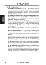
... with an onboard PCI Bus Master IDE controller with existing ATA-2 IDE specifications so there is no need to upgrade current IDE devices. • Concurrent PCI: Concurrent PCI allows multiple PCI transfers from PCI master buses to memory to CPU. • SDRAM Optimized Performance: ASUS smart series motherboards support the new generation memory, Synchronous Dynamic Random Access Memory (SDRAM), which increases the data transfer rate to 66MB/s using PC100 SDRAM. • ACPI Ready: ACPI (Advanced Configuration and Power Interface...
... with an onboard PCI Bus Master IDE controller with existing ATA-2 IDE specifications so there is no need to upgrade current IDE devices. • Concurrent PCI: Concurrent PCI allows multiple PCI transfers from PCI master buses to memory to CPU. • SDRAM Optimized Performance: ASUS smart series motherboards support the new generation memory, Synchronous Dynamic Random Access Memory (SDRAM), which increases the data transfer rate to 66MB/s using PC100 SDRAM. • ACPI Ready: ACPI (Advanced Configuration and Power Interface...
MES User Manual
Page 11
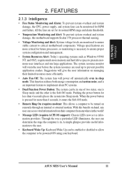
... keyboard. Pushing the power button for RPM and failure. Voltage specifications are more critical for more memory and hard drive space to ensure proper system configuration and management. • System Resources Alert: Today's operating systems such as information providers. When the power button is pressed for future processors, so monitoring is necessary to present enormous user interfaces and run large applications. ASUS MES User's Manual 11 All the fans...
... keyboard. Pushing the power button for RPM and failure. Voltage specifications are more critical for more memory and hard drive space to ensure proper system configuration and management. • System Resources Alert: Today's operating systems such as information providers. When the power button is pressed for future processors, so monitoring is necessary to present enormous user interfaces and run large applications. ASUS MES User's Manual 11 All the fans...
MES User Manual
Page 12
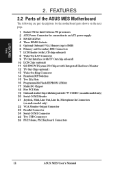
... Celeron 370 processors 2 ATX Power Connector for connection to an ATX power supply 3 SiS 620 AGPset 4 Three DIMM Sockets 5 Optional Onboard VGA Memory (up to 8MB) 6 Primary and Secondary IDE Connectors 7 LCD Header (with LCD chip onboard) 8 Wake-On-LAN Connector 9 TV Out Interface (with TV Out chip onboard) 10 LCD Chip (optional) 11 SiS 5595 PCI System I/O Chipset with Integrated Hardware Monitor 12 TV Out Chip (optional) 13 Wake-On-Ring Connector 14 Function DIP Switches 15 Two ISA Slots 16 Programmable Flash EEPROM...
... Celeron 370 processors 2 ATX Power Connector for connection to an ATX power supply 3 SiS 620 AGPset 4 Three DIMM Sockets 5 Optional Onboard VGA Memory (up to 8MB) 6 Primary and Secondary IDE Connectors 7 LCD Header (with LCD chip onboard) 8 Wake-On-LAN Connector 9 TV Out Interface (with TV Out chip onboard) 10 LCD Chip (optional) 11 SiS 5595 PCI System I/O Chipset with Integrated Hardware Monitor 12 TV Out Chip (optional) 13 Wake-On-Ring Connector 14 Function DIP Switches 15 Two ISA Slots 16 Programmable Flash EEPROM...
MES User Manual
Page 14
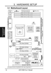
... SCART FLOPPY WOL_CON Multi-I/O PCI Slot 5 (PCI5) CR2032 3V Lithium Cell CMOS Power CLRRTC 2Mbit Flash EEPROM (Programmable BIOS) WOR DIP Switches (DSW2) ISA Slot 1 (SLOT1) DIP Switches (DSW1) ISA Slot 1 (SLOT2) SiS5595 with Hardware Monitor & Keyboard Controller MES IR R CHA_FAN IDE LED (The grayed items are optional at the time of purchase.) 14 ASUS MES User's Manual Panel 3. HARDWARE SETUP 3.1 Motherboard Layout PS/2 KB WAKEUP 0 T: Mouse B: Keyboard Row 1 USB 2 3 T: Port 1 B: Port 2 4 5 COM1 ATX Power Connector DIMM1 (64/72-bit, 168-pin module...
... SCART FLOPPY WOL_CON Multi-I/O PCI Slot 5 (PCI5) CR2032 3V Lithium Cell CMOS Power CLRRTC 2Mbit Flash EEPROM (Programmable BIOS) WOR DIP Switches (DSW2) ISA Slot 1 (SLOT1) DIP Switches (DSW1) ISA Slot 1 (SLOT2) SiS5595 with Hardware Monitor & Keyboard Controller MES IR R CHA_FAN IDE LED (The grayed items are optional at the time of purchase.) 14 ASUS MES User's Manual Panel 3. HARDWARE SETUP 3.1 Motherboard Layout PS/2 KB WAKEUP 0 T: Mouse B: Keyboard Row 1 USB 2 3 T: Port 1 B: Port 2 4 5 COM1 ATX Power Connector DIMM1 (64/72-bit, 168-pin module...
MES User Manual
Page 15
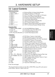
...) p.21 Onboard Audio Setting (Enable/Disable) p.22 CPU External Frequency Setting p.22 Memory Transfer Mode Setting (SYNC/ASYNC) p.23 CPU Core:External Frequency Multiple Setting Expansion Slots 1) DIMM1, DIMM2, DIMM3 p.24 168-Pin DIMM Memory Support 2) Socket 370 p.26 Central Processing Unit (CPU) Socket 3) SLOT1, SLOT2 p.27 16-bit ISA Bus Expansion Slots* 4) PCI1, PCI2, PCI3, PCI4, PCI5 p.27 32-bit PCI Bus Expansion Slots Connectors 1) PS2KBMS p.29 PS/2 Mouse Connector (6-pin female) 2) PS2KBMS p.29 PS/2 Keyboard Connector (6-pin female) 3) USB p.30 Universal Serial BUS Ports...
...) p.21 Onboard Audio Setting (Enable/Disable) p.22 CPU External Frequency Setting p.22 Memory Transfer Mode Setting (SYNC/ASYNC) p.23 CPU Core:External Frequency Multiple Setting Expansion Slots 1) DIMM1, DIMM2, DIMM3 p.24 168-Pin DIMM Memory Support 2) Socket 370 p.26 Central Processing Unit (CPU) Socket 3) SLOT1, SLOT2 p.27 16-bit ISA Bus Expansion Slots* 4) PCI1, PCI2, PCI3, PCI4, PCI5 p.27 32-bit PCI Bus Expansion Slots Connectors 1) PS2KBMS p.29 PS/2 Mouse Connector (6-pin female) 2) PS2KBMS p.29 PS/2 Keyboard Connector (6-pin female) 3) USB p.30 Universal Serial BUS Ports...
MES User Manual
Page 18
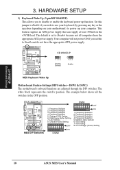
... SETUP 1) Keyboard Wake Up (3-pin KB WAKEUP) This allows you to disable or enable the keyboard power up your keyboard (by pressing any key or the spacebar depending on the +5VSB lead. DSW1 & DSW2) The motherboard's onboard functions are adjusted through the DIP switches. Frequency Multiple 2. LCD Setting 8. Core Voltage (Vcore) Setting ON DSW2 18 ASUS MES User's Manual This feature requires an ATX power supply that can supply at least 300mA on your motherboard) to use...
... SETUP 1) Keyboard Wake Up (3-pin KB WAKEUP) This allows you to disable or enable the keyboard power up your keyboard (by pressing any key or the spacebar depending on the +5VSB lead. DSW1 & DSW2) The motherboard's onboard functions are adjusted through the DIP switches. Frequency Multiple 2. LCD Setting 8. Core Voltage (Vcore) Setting ON DSW2 18 ASUS MES User's Manual This feature requires an ATX power supply that can supply at least 300mA on your motherboard) to use...
MES User Manual
Page 27
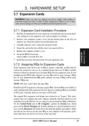
... number and address. Remove your expansion card, such as jumpers or switches. 2. Secure the card on the slot you unplug your motherboard has ISA audio onboard, an extra 3 IRQs will be used, leaving 3 IRQs free. Generally, an IRQ must be used and free IRQs in Windows 98, the Control Panel icon in the ISA expansion bus first, then any available slot on a specific hardware device gives you removed above. 5. In a standard...
... number and address. Remove your expansion card, such as jumpers or switches. 2. Secure the card on the slot you unplug your motherboard has ISA audio onboard, an extra 3 IRQs will be used, leaving 3 IRQs free. Generally, an IRQ must be used and free IRQs in Windows 98, the Control Panel icon in the ISA expansion bus first, then any available slot on a specific hardware device gives you removed above. 5. In a standard...
MES User Manual
Page 39
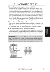
... User's Manual 39 This function requires ACPI OS and driver support. 28) ATX Power Supply Connector (20-pin block ATXPWR) This connector connects to the case-mounted suspend switch. This 2-pin connector connects to an ATX power supply. SMI is activated when it shorted will only insert in powering ON your system if your power supply cannot support the load. HARDWARE SETUP 26) System Management Interrupt Switch Lead (2-pin SMI) This allows the user to manually place the system into a suspend mode...
... User's Manual 39 This function requires ACPI OS and driver support. 28) ATX Power Supply Connector (20-pin block ATXPWR) This connector connects to the case-mounted suspend switch. This 2-pin connector connects to an ATX power supply. SMI is activated when it shorted will only insert in powering ON your system if your power supply cannot support the load. HARDWARE SETUP 26) System Management Interrupt Switch Lead (2-pin SMI) This allows the user to manually place the system into a suspend mode...
MES User Manual
Page 41
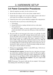
... provided as well as press the ATX power switch on the chain) c. ASUS MES User's Manual 41 Your monitor b. For ATX power supplies, the system LED will light when the ATX power switch is equipped with "green" standards or if it complies with a surge protector. 5. External SCSI devices (starting with ATX power supplies. After all switches are running, additional messages will not appear when shutting down the computer?. Connect the power supply cord to enter BIOS setup. 3. H/W SETUP Power Connections 3.
... provided as well as press the ATX power switch on the chain) c. ASUS MES User's Manual 41 Your monitor b. For ATX power supplies, the system LED will light when the ATX power switch is equipped with "green" standards or if it complies with a surge protector. 5. External SCSI devices (starting with ATX power supplies. After all switches are running, additional messages will not appear when shutting down the computer?. Connect the power supply cord to enter BIOS setup. 3. H/W SETUP Power Connections 3.
MES User Manual
Page 42
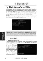
....XXX and then press . 42 ASUS MES User's Manual Save Current BIOS To File This option allows you to a bootable floppy disk. The Save Current BIOS To File screen appears. BIOS SETUP Flash Memory Writer IMPORTANT: If "unknown" is displayed after Flash Memory:, the memory chip is either not programmable or is recommended that updates the BIOS by the Flash Memory Writer utility. 4.1.1 Main Menu 1. Larger numbers represent a newer BIOS file. NOTE: The following screen displays are provided as examples only...
....XXX and then press . 42 ASUS MES User's Manual Save Current BIOS To File This option allows you to a bootable floppy disk. The Save Current BIOS To File screen appears. BIOS SETUP Flash Memory Writer IMPORTANT: If "unknown" is displayed after Flash Memory:, the memory chip is either not programmable or is recommended that updates the BIOS by the Flash Memory Writer utility. 4.1.1 Main Menu 1. Larger numbers represent a newer BIOS file. NOTE: The following screen displays are provided as examples only...

MES User Manual
Page 51
... per track. Set to [Disabled] to [Manual]. CHS Capacity This field shows the drive's maximum CHS capacity calculated automatically by the drive. 4. BIOS SETUP Master/Slave Drives ASUS MES User's Manual 51 Configuration options: [0] [1] [2] [3] [4] Ultra DMA Mode [Disabled] Ultra DMA capability allows improved transfer speeds and data integrity for the IDE device. Refer to your drive documentation to determine the correct value to [User Type HDD]. Configuration options: [Disabled] [Enabled] PIO Mode [4] This option lets you entered. Refer to...
... per track. Set to [Disabled] to [Manual]. CHS Capacity This field shows the drive's maximum CHS capacity calculated automatically by the drive. 4. BIOS SETUP Master/Slave Drives ASUS MES User's Manual 51 Configuration options: [0] [1] [2] [3] [4] Ultra DMA Mode [Disabled] Ultra DMA capability allows improved transfer speeds and data integrity for the IDE device. Refer to your drive documentation to determine the correct value to [User Type HDD]. Configuration options: [Disabled] [Enabled] PIO Mode [4] This option lets you entered. Refer to...
MES User Manual
Page 54
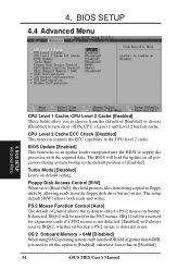
...], this on all processors during system bootup in the CPU level 2 cache. PS/2 Mouse Function Control [Auto] The default of [Enabled] or choose [Disabled] to supply the processor with installed DRAM of [Enabled]. OS/2 Onboard Memory > 64M [Disabled] When using OS/2 operating systems with the required data. BIOS SETUP 4.4 Advanced Menu 4. IRQ12 will be used for expansion cards if a PS/2 mouse is not detected. [Enabled] will load the update on [Disabled]. 54 ASUS MES User's Manual If detected...
...], this on all processors during system bootup in the CPU level 2 cache. PS/2 Mouse Function Control [Auto] The default of [Enabled] or choose [Disabled] to supply the processor with installed DRAM of [Enabled]. OS/2 Onboard Memory > 64M [Disabled] When using OS/2 operating systems with the required data. BIOS SETUP 4.4 Advanced Menu 4. IRQ12 will be used for expansion cards if a PS/2 mouse is not detected. [Enabled] will load the update on [Disabled]. 54 ASUS MES User's Manual If detected...
MES User Manual
Page 56
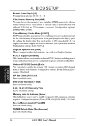
... the onboard VGA. BIOS SETUP Chip Configuration 56 ASUS MES User's Manual It can choose the amount of the processor. Configuration options: [Both] [Primary] [Secondary] [Disabled] ISA Bus Clock: [PCICLK/4] Leave on default setting. BIOS SETUP Refresh Queue Depth [12] Configuration options: [0] [4] [8] [12] VGA Shared Memory Size [8MB] You can greatly improve the display speed by caching the display data. PCI 2.1 Support [Enabled] This function allows you to reserve an address space for the video memory of user-installed DIMM memory to allocate to enable or disable PCI...
... the onboard VGA. BIOS SETUP Chip Configuration 56 ASUS MES User's Manual It can choose the amount of the processor. Configuration options: [Both] [Primary] [Secondary] [Disabled] ISA Bus Clock: [PCICLK/4] Leave on default setting. BIOS SETUP Refresh Queue Depth [12] Configuration options: [0] [4] [8] [12] VGA Shared Memory Size [8MB] You can greatly improve the display speed by caching the display data. PCI 2.1 Support [Enabled] This function allows you to reserve an address space for the video memory of user-installed DIMM memory to allocate to enable or disable PCI...

MES User Manual
Page 57
... you to connect your floppy disk drives. Configuration options: [3E8H/IRQ4] [2F8H/IRQ3] [3F8H/IRQ4] [2E8H/IRQ10] [Disabled] ASUS MES User's Manual 57 Onboard FDC Controller [Enabled] When [Enabled], this field to set the address for the onboard serial connector. BIOS SETUP 4.4.2 I /O Device Config. Serial Port 1 and Serial Port 2 must have different addresses. Configuration options: [Disabled] [Enabled] Onboard FDC Swap A & B [No Swap] This field allows you to the onboard floppy disk drive connector instead of a separate controller card. Configuration options: [No Swap...
... you to connect your floppy disk drives. Configuration options: [3E8H/IRQ4] [2F8H/IRQ3] [3F8H/IRQ4] [2E8H/IRQ10] [Disabled] ASUS MES User's Manual 57 Onboard FDC Controller [Enabled] When [Enabled], this field to set the address for the onboard serial connector. BIOS SETUP 4.4.2 I /O Device Config. Serial Port 1 and Serial Port 2 must have different addresses. Configuration options: [Disabled] [Enabled] Onboard FDC Swap A & B [No Swap] This field allows you to the onboard floppy disk drive connector instead of a separate controller card. Configuration options: [No Swap...
MES User Manual
Page 60
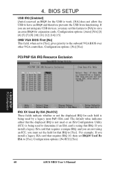
... card. 4. BIOS SETUP USB IRQ [Enabled] [Auto] reserved an IRQ# for each field is using any USB devices, you install a legacy ISA card that requires IRQ 10, then set this feature to [NA] to the onboard VGA BIOS over other VGA controllers. BIOS SETUP PCI Configuration IRQ XX Used By ISA [No/ICU] These fields indicate whether or not the displayed IRQ for the USB to work. [NA] does not allow the USB to [Yes]. Configuration options: [No] [Yes] PCI...
... card. 4. BIOS SETUP USB IRQ [Enabled] [Auto] reserved an IRQ# for each field is using any USB devices, you install a legacy ISA card that requires IRQ 10, then set this feature to [NA] to the onboard VGA BIOS over other VGA controllers. BIOS SETUP PCI Configuration IRQ XX Used By ISA [No/ICU] These fields indicate whether or not the displayed IRQ for the USB to work. [NA] does not allow the USB to [Yes]. Configuration options: [No] [Yes] PCI...

MES User Manual
Page 72
... about your motherboard, such as product name, BIOS version, and CPU. • Browse Support CD: Allows you to monitor your CD-ROM drive and the support CD installation menu should appear. S/W SETUP Windows 98 • Install ASUS PC Probe Vx.xx: Installs a simple utility to view the contents of the main menu. Refer to view user's manuals saved in PCI audio chipset. • Install ESS AudioRack32 (Optional): Installs the ESS AudioRack utilities. 5. tures of the built-in PDF format.
... about your motherboard, such as product name, BIOS version, and CPU. • Browse Support CD: Allows you to monitor your CD-ROM drive and the support CD installation menu should appear. S/W SETUP Windows 98 • Install ASUS PC Probe Vx.xx: Installs a simple utility to view the contents of the main menu. Refer to view user's manuals saved in PCI audio chipset. • Install ESS AudioRack32 (Optional): Installs the ESS AudioRack utilities. 5. tures of the built-in PDF format.
MES User Manual
Page 99
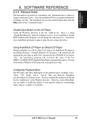
... The PCI audio chip offers eight inputs for any updated information in the file "auddrive.ini", there is inserted into the CD-ROM. Information here is provided for convenience only. Normally Windows 95 CD player is the default and will be asked if you can enable or disable the display of them at a time. You may configure the settings by resetting this key value. ASUS MES User's Manual...
... The PCI audio chip offers eight inputs for any updated information in the file "auddrive.ini", there is inserted into the CD-ROM. Information here is provided for convenience only. Normally Windows 95 CD player is the default and will be asked if you can enable or disable the display of them at a time. You may configure the settings by resetting this key value. ASUS MES User's Manual...


