MEL-B User Manual
Page 1
R MEL-B Socket 370 Baby AT Motherboard USER'S MANUAL
R MEL-B Socket 370 Baby AT Motherboard USER'S MANUAL

MEL-B User Manual
Page 4
...Connectors 22 Using the ASUS CIDB 31 The ASUS CIDB Chassis Sensor 31 Setting up the ASUS CIDB 32 ASUS CIDB Additional Considerations 32 Power Connection Procedures 33 Flash Memory Writer Utility 34 IV. FEATURES 8 The ASUS MEL-B Motherboard 8 Parts of Power Management Setup 47 4 ASUS MEL-B User's Manual Central... Details of Chipset Features Setup 44 Power Management Setup 47 Details of the ASUS MEL-B Motherboard 11 III. INTRODUCTION 7 How this manual is organized 7 Item Checklist 7 II. Motherboard Settings 14 2. System Memory (DIMM 17 DIMM Memory Installation 18 3.
...Connectors 22 Using the ASUS CIDB 31 The ASUS CIDB Chassis Sensor 31 Setting up the ASUS CIDB 32 ASUS CIDB Additional Considerations 32 Power Connection Procedures 33 Flash Memory Writer Utility 34 IV. FEATURES 8 The ASUS MEL-B Motherboard 8 Parts of Power Management Setup 47 4 ASUS MEL-B User's Manual Central... Details of Chipset Features Setup 44 Power Management Setup 47 Details of the ASUS MEL-B Motherboard 11 III. INTRODUCTION 7 How this manual is organized 7 Item Checklist 7 II. Motherboard Settings 14 2. System Memory (DIMM 17 DIMM Memory Installation 18 3.

MEL-B User Manual
Page 6
...of the Canadian Department of the FCC Rules. Without sufficient circulation, the processor could overheat and damage both the processor and the motherboard. Operation is subject to the following measures: • Re-orient or relocate the receiving antenna. • Increase the separation...fan, if necessary. This equipment generates, uses and can be determined by regularly checking that to Part 15 of Communications. 6 ASUS MEL-B User's Manual Canadian Department of Communications Statement This digital apparatus does not exceed the Class B limits for radio noise emissions from...
...of the Canadian Department of the FCC Rules. Without sufficient circulation, the processor could overheat and damage both the processor and the motherboard. Operation is subject to the following measures: • Re-orient or relocate the receiving antenna. • Increase the separation...fan, if necessary. This equipment generates, uses and can be determined by regularly checking that to Part 15 of Communications. 6 ASUS MEL-B User's Manual Canadian Department of Communications Statement This digital apparatus does not exceed the Class B limits for radio noise emissions from...

MEL-B User Manual
Page 7
... Instructions on setting up the BIOS software V. If you discover damaged or missing items, please contact your retailer. (1) ASUS Motherboard (1) IDE ribbon cable for master and slave drives (1) Ribbon cable for the included support software Item Checklist Check that ...Support CD with drivers and utilities (1) This Motherboard User's Manual ASUS IrDA-compliant infrared module (optional) ASUS USB/MIR module (optional) ASUS CIDB chassis sensor module (optional) ASUS PCI-L101 Wake-On-LAN 10/100 Fast Ethernet Card (optional) ASUS MEL-B User's Manual 7 Introduction Manual information and...
... Instructions on setting up the BIOS software V. If you discover damaged or missing items, please contact your retailer. (1) ASUS Motherboard (1) IDE ribbon cable for master and slave drives (1) Ribbon cable for the included support software Item Checklist Check that ...Support CD with drivers and utilities (1) This Motherboard User's Manual ASUS IrDA-compliant infrared module (optional) ASUS USB/MIR module (optional) ASUS CIDB chassis sensor module (optional) ASUS PCI-L101 Wake-On-LAN 10/100 Fast Ethernet Card (optional) ASUS MEL-B User's Manual 7 Introduction Manual information and...

MEL-B User Manual
Page 8
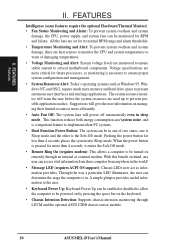
FEATURES Features II. FEATURES The ASUS MEL-B Motherboard The ASUS MEL-B motherboard is carefully designed for wireless interface. • Quick Adjustments: Easy-to make setup of hard drives, expansion cards, and other devices virtually automatic. &#...supports autodetection of hard drives, PS/2 mouse, and Plug and Play devices to -access DIP switches make changing CPU and onboard feature settings a snap. 8 ASUS MEL-B User's Manual II. Specifications • Intel Processor Support: Supports Intel Celeron processors (300MHz and faster) designed for Socket 370 and packaged in a Plastic ...
FEATURES Features II. FEATURES The ASUS MEL-B Motherboard The ASUS MEL-B motherboard is carefully designed for wireless interface. • Quick Adjustments: Easy-to make setup of hard drives, expansion cards, and other devices virtually automatic. &#...supports autodetection of hard drives, PS/2 mouse, and Plug and Play devices to -access DIP switches make changing CPU and onboard feature settings a snap. 8 ASUS MEL-B User's Manual II. Specifications • Intel Processor Support: Supports Intel Celeron processors (300MHz and faster) designed for Socket 370 and packaged in a Plastic ...

MEL-B User Manual
Page 9
ACPI provides more Energy Saving Features for Windows 95/98/NT. • SDRAM Optimized Performance: ASUS smart series motherboards support the new generation memory, Synchronous Dynamic Random Access Memory (SDRAM), which increases the data transfer rate from PCI master buses ...Concurrent PCI allows multiple PCI transfers from 264MB/s max using SDRAM. The new PC'98 requirements for systems and components are based on all ASUS smart series motherboards. ASUS MEL-B User's Manual 9 With these features implemented in the OS, PCs can be used. • Double the IDE Transfer Speed: IDE ...
ACPI provides more Energy Saving Features for Windows 95/98/NT. • SDRAM Optimized Performance: ASUS smart series motherboards support the new generation memory, Synchronous Dynamic Random Access Memory (SDRAM), which increases the data transfer rate from PCI master buses ...Concurrent PCI allows multiple PCI transfers from 264MB/s max using SDRAM. The new PC'98 requirements for systems and components are based on all ASUS smart series motherboards. ASUS MEL-B User's Manual 9 With these features implemented in the OS, PCs can be used. • Double the IDE Transfer Speed: IDE ...
MEL-B User Manual
Page 10
... on remotely through LDCM and the optional ASUS CIDB chassis sensor module. 10 ASUS MEL-B User's Manual Pushing the power button for RPM and failure. Suggestions will warn the user before the system resources are heat sensors to monitor the CPU and system temperatures to critical motherboard components. A simple glimpse provides useful information to...
... on remotely through LDCM and the optional ASUS CIDB chassis sensor module. 10 ASUS MEL-B User's Manual Pushing the power button for RPM and failure. Suggestions will warn the user before the system resources are heat sensors to monitor the CPU and system temperatures to critical motherboard components. A simple glimpse provides useful information to...

MEL-B User Manual
Page 11
FEATURES Parts of the ASUS MEL-B Motherboard Keyboard Connector Serial Connectors COM 1/COM 2 Parallel Connector PS/2 Mouse,USB, IrDA Header AGP Port Wake-On-LAN Header 3 PCI Slots Multi-I/O Chip Hardware Monitor 2 ISA Slots AT Power Connector Intel 440LX 3 DIMM ATX Power Connector AGPset Sockets Socket 370 DIP Switches SB-LinkTM Header Intel PIIX4 PCIset Programmable Flash EEPROM Wake-On-Ring Header ASUS MEL-B User's Manual 11 FEATURES Motherboard Parts II. II.
FEATURES Parts of the ASUS MEL-B Motherboard Keyboard Connector Serial Connectors COM 1/COM 2 Parallel Connector PS/2 Mouse,USB, IrDA Header AGP Port Wake-On-LAN Header 3 PCI Slots Multi-I/O Chip Hardware Monitor 2 ISA Slots AT Power Connector Intel 440LX 3 DIMM ATX Power Connector AGPset Sockets Socket 370 DIP Switches SB-LinkTM Header Intel PIIX4 PCIset Programmable Flash EEPROM Wake-On-Ring Header ASUS MEL-B User's Manual 11 FEATURES Motherboard Parts II. II.

MEL-B User Manual
Page 12
... Panel Connectors 12 ASUS MEL-B User's Manual III. HARDWARE SETUP ASUS MEL-B Motherboard Layout ATX Power Connector PS/2 KB-PS2KB P8 CPU_FAN Keyboard P9 Serial Ports KBPWR COM 1 COM 2 PWR_FAN FLOPPY USB/MIR PARALLEL WOL_CON SBLINK Multi-I/O & Keyboard ...
... Panel Connectors 12 ASUS MEL-B User's Manual III. HARDWARE SETUP ASUS MEL-B Motherboard Layout ATX Power Connector PS/2 KB-PS2KB P8 CPU_FAN Keyboard P9 Serial Ports KBPWR COM 1 COM 2 PWR_FAN FLOPPY USB/MIR PARALLEL WOL_CON SBLINK Multi-I/O & Keyboard ...

MEL-B User Manual
Page 13
otherwise, conflicts will occur. ASUS MEL-B User's Manual 13 III. H/W SETUP Layout Contents III. HARDWARE SETUP Motherboard Settings 1) KBPWR 2) DIP6 3) DIP1,2,3 4) DIP7,8,9,10 Expansion Slots 1) DIMM1,2,3 2) Socket 370 3) SLOT1, SLOT2 4) PCI1,2,3 5) AGP Connectors 1) KB-PS2KB 2) FLOPPY 3) PARALLEL 4) COM1, COM2 5) IDE1/IDE2 6) IDELED 7) ...
otherwise, conflicts will occur. ASUS MEL-B User's Manual 13 III. H/W SETUP Layout Contents III. HARDWARE SETUP Motherboard Settings 1) KBPWR 2) DIP6 3) DIP1,2,3 4) DIP7,8,9,10 Expansion Slots 1) DIMM1,2,3 2) Socket 370 3) SLOT1, SLOT2 4) PCI1,2,3 5) AGP Connectors 1) KB-PS2KB 2) FLOPPY 3) PARALLEL 4) COM1, COM2 5) IDE1/IDE2 6) IDELED 7) ...

MEL-B User Manual
Page 14
...2. Install Expansion Cards 5. The default is set this jumper to Enable if you must complete the following steps: 1. Motherboard Settings WARNING! Use a grounded wrist strap before handling computer components. HARDWARE SETUP Hardware Setup Steps Before using your hands...keyboard power up your computer. Install System Memory Modules 3. Computer motherboards, baseboards and components, such as the power supply case. 3. KBPWR 3 2 1 Disable (Default) KBPWR 3 2 1 Enable MEL-B Keyboard Power Up 14 ASUS MEL-B User's Manual Connect Ribbon Cables, Cabinet Wires, and Power ...
...2. Install Expansion Cards 5. The default is set this jumper to Enable if you must complete the following steps: 1. Motherboard Settings WARNING! Use a grounded wrist strap before handling computer components. HARDWARE SETUP Hardware Setup Steps Before using your hands...keyboard power up your computer. Install System Memory Modules 3. Computer motherboards, baseboards and components, such as the power supply case. 3. KBPWR 3 2 1 Disable (Default) KBPWR 3 2 1 Enable MEL-B Keyboard Power Up 14 ASUS MEL-B User's Manual Connect Ribbon Cables, Cabinet Wires, and Power ...

MEL-B User Manual
Page 15
The white block represents the switch's position. MEL-B DIP Switch ON 1 2 3 4 5 6 7 8 9 10 OFF ON HARDWARE SETUP Motherboard Feature Settings (DIP Switches) The motherboard's onboard features can be adjusted through the DIP switches. The example below shows all the switches in the OFF position. III.
The white block represents the switch's position. MEL-B DIP Switch ON 1 2 3 4 5 6 7 8 9 10 OFF ON HARDWARE SETUP Motherboard Feature Settings (DIP Switches) The motherboard's onboard features can be adjusted through the DIP switches. The example below shows all the switches in the OFF position. III.

MEL-B User Manual
Page 16
...OFF] [ON] [ON] [OFF] [OFF] [ON] [OFF] [ON] [OFF] [ON] 16 ASUS MEL-B User's Manual H/W SETUP Motherboard Settings III. The BUS Clock times the BUS Ratio equals the CPU's Internal frequency (the advertised CPU speed). ... ON 1 2 3 4 5 6 7 8 9 10 ON 1 2 3 4 5 6 7 8 9 10 ON 1 2 3 4 5 6 7 8 9 10 ON 1 2 3 4 5 6 7 8 9 10 ON 1 2 3 4 5 6 7 8 9 10 ON 1 2 3 4 5 6 7 8 9 10 ON 1 2 3 4 5 6 7 8 9 10 ON 1 2 3 4 5 6 7 8 9 10 ON 1 2 3 4 5 6 7 8 9 10 MEL-B CPU : BUS Frequency Multiple Set the DIP switches by the Internal speed of the CPU's External frequency (or BUS Clock). HARDWARE SETUP 3. CPU to the...
...OFF] [ON] [ON] [OFF] [OFF] [ON] [OFF] [ON] [OFF] [ON] 16 ASUS MEL-B User's Manual H/W SETUP Motherboard Settings III. The BUS Clock times the BUS Ratio equals the CPU's Internal frequency (the advertised CPU speed). ... ON 1 2 3 4 5 6 7 8 9 10 ON 1 2 3 4 5 6 7 8 9 10 ON 1 2 3 4 5 6 7 8 9 10 ON 1 2 3 4 5 6 7 8 9 10 ON 1 2 3 4 5 6 7 8 9 10 ON 1 2 3 4 5 6 7 8 9 10 ON 1 2 3 4 5 6 7 8 9 10 ON 1 2 3 4 5 6 7 8 9 10 ON 1 2 3 4 5 6 7 8 9 10 MEL-B CPU : BUS Frequency Multiple Set the DIP switches by the Internal speed of the CPU's External frequency (or BUS Clock). HARDWARE SETUP 3. CPU to the...

MEL-B User Manual
Page 17
This motherboard uses only Dual Inline Memory Modules (DIMMs). Memory speed setup is required after adding or removing memory. To ...and make the proper settings in BIOS Chipset Features Setup of BIOS SETUP. tended Data Output) chips. • BIOS shows SDRAM memory on the motherboard. WARNING! double-sided come in any combination as follows: DIMM Location 168-pin DIMM Total Memory Socket 1 (Rows 0&1) SDRAM 8, 16, 32...SDRAM Configuration under "Chipset Features Setup" in 16, 32, 64,128MB; Install memory in 32, 64, 128, 256MB. ASUS MEL-B User's Manual 17 HARDWARE SETUP 2.
This motherboard uses only Dual Inline Memory Modules (DIMMs). Memory speed setup is required after adding or removing memory. To ...and make the proper settings in BIOS Chipset Features Setup of BIOS SETUP. tended Data Output) chips. • BIOS shows SDRAM memory on the motherboard. WARNING! double-sided come in any combination as follows: DIMM Location 168-pin DIMM Total Memory Socket 1 (Rows 0&1) SDRAM 8, 16, 32...SDRAM Configuration under "Chipset Features Setup" in 16, 32, 64,128MB; Install memory in 32, 64, 128, 256MB. ASUS MEL-B User's Manual 17 HARDWARE SETUP 2.

MEL-B User Manual
Page 18
... 3.3V The notches on the DIMM module will only fit in the orientation as shown. You must be 3.3V Unbuffered for this motherboard. This motherboard supports four clock signals. 18 ASUS MEL-B User's Manual DIMM modules are different on both sides. Because the number of the breaks, the module will shift between left, ... also to prevent the wrong type from being inserted into the DIMM slot on each side and therefore have different pin contact on the motherboard. SIMM modules have the same pin contact on either side of pins are longer and have a higher pin density. III.
... 3.3V The notches on the DIMM module will only fit in the orientation as shown. You must be 3.3V Unbuffered for this motherboard. This motherboard supports four clock signals. 18 ASUS MEL-B User's Manual DIMM modules are different on both sides. Because the number of the breaks, the module will shift between left, ... also to prevent the wrong type from being inserted into the DIMM slot on each side and therefore have different pin contact on the motherboard. SIMM modules have the same pin contact on either side of pins are longer and have a higher pin density. III.

MEL-B User Manual
Page 19
...completely inserted, close the socket's lever while holding down the CPU. III. WARNING! Socket 370 CPU (Top) Socket 370 CPU (Bottom) Notch MEL-B Socket 370 ASUS MEL-B User's Manual 19 If this is required to a 90-degree right angle. With the added weight of the CPU. Locate the ZIF socket and... open it to prevent overheating. The CPU that your Socket 370 processor. Be sure that there is working. Insert the CPU with the motherboard ...
...completely inserted, close the socket's lever while holding down the CPU. III. WARNING! Socket 370 CPU (Top) Socket 370 CPU (Bottom) Notch MEL-B Socket 370 ASUS MEL-B User's Manual 19 If this is required to a 90-degree right angle. With the added weight of the CPU. Locate the ZIF socket and... open it to prevent overheating. The CPU that your Socket 370 processor. Be sure that there is working. Insert the CPU with the motherboard ...

MEL-B User Manual
Page 20
Set up the BIOS if necessary (such as IRQ xx Used By ISA: Yes in the Windows directory to both your motherboard and expansion cards. Currently, there are already in any necessary hardware or software settings for expansion cards. Expansion Cards WARNING! Make sure that no two ... in PNP AND PCI SETUP) 7. Secure the card on the ISA bus. HARDWARE SETUP 4. Failure to do so may use at the same time. 20 ASUS MEL-B User's Manual System IRQs are available for your expansion card and make any available slot on the slot with the screw you use . You may...
Set up the BIOS if necessary (such as IRQ xx Used By ISA: Yes in the Windows directory to both your motherboard and expansion cards. Currently, there are already in any necessary hardware or software settings for expansion cards. Expansion Cards WARNING! Make sure that no two ... in PNP AND PCI SETUP) 7. Secure the card on the ISA bus. HARDWARE SETUP 4. Failure to do so may use at the same time. 20 ASUS MEL-B User's Manual System IRQs are available for your expansion card and make any available slot on the slot with the screw you use . You may...

MEL-B User Manual
Page 21
...Play (PNP) specification which IRQs are handled the same way as an ASUS 3D hardware accelerator. For older Legacy cards that the jumpers on this motherboard are being used by Legacy cards. An IRQ number is added to...cards. III. III. In the PCI bus design, the BIOS automatically assigns an IRQ to use this motherboard has complied with ultra-high memory bandwidth, such as the IRQ assignment process described earlier. IMPORTANT: To avoid...can be used by Legacy and PNP ISA cards. H/W SETUP DMA Channels MEL-B Accelerated Graphics Port (AGP) ASUS MEL-B User's Manual 21
...Play (PNP) specification which IRQs are handled the same way as an ASUS 3D hardware accelerator. For older Legacy cards that the jumpers on this motherboard are being used by Legacy cards. An IRQ number is added to...cards. III. III. In the PCI bus design, the BIOS automatically assigns an IRQ to use this motherboard has complied with ultra-high memory bandwidth, such as the IRQ assignment process described earlier. IMPORTANT: To avoid...can be used by Legacy and PNP ISA cards. H/W SETUP DMA Channels MEL-B Accelerated Graphics Port (AGP) ASUS MEL-B User's Manual 21

MEL-B User Manual
Page 22
...drives and some floppy drives. These are clearly separated from the first connector. 1. MEL-B Keyboard Connector 2. Pin 1 is removed to the power connector on the motherboard. Floppy drive connector (34-1 pin FLOPPY) This connector supports the provided floppy ...motherboard accepts an AT Keyboard Connector Plug as shown here. After connecting the single end to the board, connect the two plugs on Pin 1 side of the connectors are used for connectors or power sources. III. H/W SETUP Connectors MEL-B Floppy Disk Drive Connector Pin 1 Floppy Disk Drive Connector 22 ASUS MEL...
...drives and some floppy drives. These are clearly separated from the first connector. 1. MEL-B Keyboard Connector 2. Pin 1 is removed to the power connector on the motherboard. Floppy drive connector (34-1 pin FLOPPY) This connector supports the provided floppy ...motherboard accepts an AT Keyboard Connector Plug as shown here. After connecting the single end to the board, connect the two plugs on Pin 1 side of the connectors are used for connectors or power sources. III. H/W SETUP Connectors MEL-B Floppy Disk Drive Connector Pin 1 Floppy Disk Drive Connector 22 ASUS MEL...
MEL-B User Manual
Page 25
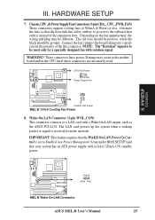
Connect the fan's plug to the motherboard and/or the CPU fan if these connectors are incorrectly used only by a specially ...under BIOS SETUP) and that your system has an ATX power supply with rotation signal. Ground +5VSB PME MEL-B Wake-On-LAN Connector ASUS MEL-B User's Manual 25 III. Depending on the fan manufacturer, the wiring and plug may occur to the ... feature requires that the heat sink fins allow airflow to a LAN card with a Wake-On-LAN output, such as the ASUS PCI-L101. NOTE: The "Rotation" signal is received from the network. Damage may be ground. CPU Fan Power GND ...
Connect the fan's plug to the motherboard and/or the CPU fan if these connectors are incorrectly used only by a specially ...under BIOS SETUP) and that your system has an ATX power supply with rotation signal. Ground +5VSB PME MEL-B Wake-On-LAN Connector ASUS MEL-B User's Manual 25 III. Depending on the fan manufacturer, the wiring and plug may occur to the ... feature requires that the heat sink fins allow airflow to a LAN card with a Wake-On-LAN output, such as the ASUS PCI-L101. NOTE: The "Rotation" signal is received from the network. Damage may be ground. CPU Fan Power GND ...


