
MEB-VM User Manual
Page 1
R MEB-VM Socket 370 AGP Motherboard USER'S MANUAL
R MEB-VM Socket 370 AGP Motherboard USER'S MANUAL
MEB-VM User Manual
Page 8
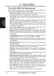
... surround and positioning capabiliy. II. FEATURES Features II. FEATURES The ASUS MEB-VM Motherboard The ASUS MEB-VM motherboard is carefully designed for the demanding PC user who wants many intelligent features in a small package. • Intel Processor Support: Supports Intel's Celeron processor designed for the Socket 370 and packaged in a Plastic Pin Grid Array (PPGA). • Intel...
... surround and positioning capabiliy. II. FEATURES Features II. FEATURES The ASUS MEB-VM Motherboard The ASUS MEB-VM motherboard is carefully designed for the demanding PC user who wants many intelligent features in a small package. • Intel Processor Support: Supports Intel's Celeron processor designed for the Socket 370 and packaged in a Plastic Pin Grid Array (PPGA). • Intel...
MEB-VM User Manual
Page 11
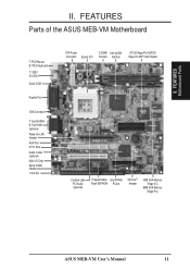
...ASUS MEB-VM Motherboard T: PS/2 Mouse B: PS/2 Keyboard T: USB 1 B: USB 2 Serial COM 1 Parallel Port VGA Connector T: Joystick/Midi B: Out/In/Mic (optional) Wake-On-LAN Header AGP Port 2 PCI Slots Audio Codec (optional) Multi-I/O Chip Serial COM2 Header 1 ISA Slot ATX Power 2 DIMM Intel 440BX Connector Socket 370 Sockets... AGPset ATI 3D Rage Pro AGP2X/ Rage IIC AGP VGA Chipset Creative Labs PCI Audio (optional) Programmable Intel PIIX4E Flash EEPROM PCIset SB-LinkTM Header 4MB VGA Memory (Rage IIC) 8MB VGA Memory (Rage Pro) ASUS MEB-VM User's Manual...
...ASUS MEB-VM Motherboard T: PS/2 Mouse B: PS/2 Keyboard T: USB 1 B: USB 2 Serial COM 1 Parallel Port VGA Connector T: Joystick/Midi B: Out/In/Mic (optional) Wake-On-LAN Header AGP Port 2 PCI Slots Audio Codec (optional) Multi-I/O Chip Serial COM2 Header 1 ISA Slot ATX Power 2 DIMM Intel 440BX Connector Socket 370 Sockets... AGPset ATI 3D Rage Pro AGP2X/ Rage IIC AGP VGA Chipset Creative Labs PCI Audio (optional) Programmable Intel PIIX4E Flash EEPROM PCIset SB-LinkTM Header 4MB VGA Memory (Rage IIC) 8MB VGA Memory (Rage Pro) ASUS MEB-VM User's Manual...
MEB-VM User Manual
Page 12
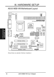
...ASUS MEB-VM Motherboard Layout PS/2 T: Mouse B:Keyboard USB T: Port 1 B:Port 2 COM1 ATXPWR BUS FREQ FS0 FS1 FS2 FS3 FS4 Row DIMM Socket 1 (64/72-bit, 168-pin module) 0 1 DIMM Socket 2 (64/72-bit, 168-pin module) 2 3 ATI Multimedia Connector (AMC) GAME_AUDIO PRINTER VGA Line Out Line In Mic In Socket 370 ...Slot 2 (PCI2) Multi-I/O & Keyboard Controller 2Mbit Flash EEPROM (Programmable BIOS) ISA Slot 1 (ISA1) Intel PIIX4E Chipset FLOPPY IR SBLINK RTCCLR FREQ MULT ASUS ASIC Buzzer PANEL (Grayed items are optional at the time of purchase.) 12 ASUS MEB-VM User's Manual
...ASUS MEB-VM Motherboard Layout PS/2 T: Mouse B:Keyboard USB T: Port 1 B:Port 2 COM1 ATXPWR BUS FREQ FS0 FS1 FS2 FS3 FS4 Row DIMM Socket 1 (64/72-bit, 168-pin module) 0 1 DIMM Socket 2 (64/72-bit, 168-pin module) 2 3 ATI Multimedia Connector (AMC) GAME_AUDIO PRINTER VGA Line Out Line In Mic In Socket 370 ...Slot 2 (PCI2) Multi-I/O & Keyboard Controller 2Mbit Flash EEPROM (Programmable BIOS) ISA Slot 1 (ISA1) Intel PIIX4E Chipset FLOPPY IR SBLINK RTCCLR FREQ MULT ASUS ASIC Buzzer PANEL (Grayed items are optional at the time of purchase.) 12 ASUS MEB-VM User's Manual

MEB-VM User Manual
Page 13
... VGA Setting (Enable/Disable) p. 15 Audio Setting (Enable/Disable) p. 16 CPU External Clock (BUS) Frequency Selection p. 16 CPU:BUS Frequency Multiple Expansion Slots 1) DIMM1, DIMM2 2) Socket 370 3) PCI1, PCI2 4) ISA1 p. 17 168-Pin DIMM Memory Support p. 19 Central Processing Unit (CPU) Support p. 20 32-bit PCI Bus Expansion Slots p. 20 16-bit...) PLED (PANEL) p. 31 System Power LED Lead (3-1 pins) 26) RESET (PANEL) p. 31 Reset Switch Lead (2 pins) 27) ATXPWR p. 32 ATX Power Supply Connector (20 pins) ASUS MEB-VM User's Manual 13
... VGA Setting (Enable/Disable) p. 15 Audio Setting (Enable/Disable) p. 16 CPU External Clock (BUS) Frequency Selection p. 16 CPU:BUS Frequency Multiple Expansion Slots 1) DIMM1, DIMM2 2) Socket 370 3) PCI1, PCI2 4) ISA1 p. 17 168-Pin DIMM Memory Support p. 19 Central Processing Unit (CPU) Support p. 20 32-bit PCI Bus Expansion Slots p. 20 16-bit...) PLED (PANEL) p. 31 System Power LED Lead (3-1 pins) 26) RESET (PANEL) p. 31 Reset Switch Lead (2 pins) 27) ATXPWR p. 32 ATX Power Supply Connector (20 pins) ASUS MEB-VM User's Manual 13
MEB-VM User Manual
Page 19
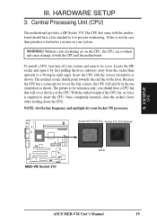
...fan attached to it by first pulling the lever sideways away from the socket then upwards to insert the CPU. NOTE: Set the bus frequency and multiple for reference only; Socket 370 CPU (Top) Socket 370 CPU (Bottom) 01 MEB-VM Socket 370 Notch ASUS MEB-VM User's Manual 19 HARDWARE SETUP 3. WARNING! The picture is required ... overheating. Insert the CPU with the motherboard should point towards the end the of the CPU fan, no force is for your Socket 370 processor. Because the CPU has a corner pin for two of the four corners, the CPU will cover the face of the CPU...
...fan attached to it by first pulling the lever sideways away from the socket then upwards to insert the CPU. NOTE: Set the bus frequency and multiple for reference only; Socket 370 CPU (Top) Socket 370 CPU (Bottom) 01 MEB-VM Socket 370 Notch ASUS MEB-VM User's Manual 19 HARDWARE SETUP 3. WARNING! The picture is required ... overheating. Insert the CPU with the motherboard should point towards the end the of the CPU fan, no force is for your Socket 370 processor. Because the CPU has a corner pin for two of the four corners, the CPU will cover the face of the CPU...


