User Guide
Page 15
... memory slots, and PCI Express 2.0/3.0 expansion slots. PCIE® 3.0 PCIE® 3.0 (PCIe 3.0) is a single chipset that provides twice the performance and speed of PCIe 2.0. Chapter 1 ASUS MAXIMUS VII HERO 1-1 LGA1150 socket for 4th/ New 4th/ 5th generation Intel® Core™ i7/Intel® Core™ i5/Intel® Core™ i3, Pentium®...
... memory slots, and PCI Express 2.0/3.0 expansion slots. PCIE® 3.0 PCIE® 3.0 (PCIe 3.0) is a single chipset that provides twice the performance and speed of PCIe 2.0. Chapter 1 ASUS MAXIMUS VII HERO 1-1 LGA1150 socket for 4th/ New 4th/ 5th generation Intel® Core™ i7/Intel® Core™ i5/Intel® Core™ i3, Pentium®...

User Guide
Page 17
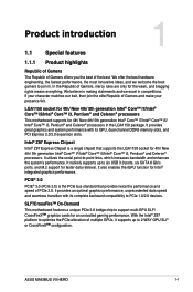
... shows what opponents and teammates are up your own setting to fire up to run faster and smoother. GameFirst III ASUS GameFirst III is an on-board solution that improves audio experience when you connect your headset's impedance and adjusts the ...management software that features four preset packet prioritized profiles (Optimization, Game, Media Streaming and File Sharing) facilitating user's need. Chapter 1 ASUS MAXIMUS VII HERO 1-3 1.1.2 ROG Gaming Features SupremeFX The re-engineered ROG-exclusive SupremeFX audio technology features an onboard 8-channel high-definition sound of true...
... shows what opponents and teammates are up your own setting to fire up to run faster and smoother. GameFirst III ASUS GameFirst III is an on-board solution that improves audio experience when you connect your headset's impedance and adjusts the ...management software that features four preset packet prioritized profiles (Optimization, Game, Media Streaming and File Sharing) facilitating user's need. Chapter 1 ASUS MAXIMUS VII HERO 1-3 1.1.2 ROG Gaming Features SupremeFX The re-engineered ROG-exclusive SupremeFX audio technology features an onboard 8-channel high-definition sound of true...
User Guide
Page 19
... optical media into as many as S/PDIF or HDMI) designed to deliver audio to gather information of the main devices of incredible surround sound. Chapter 1 ASUS MAXIMUS VII HERO 1-5 DTS Interactive is based on personal computers, and sending encoded bitstreams out of a digital audio connection (such as 7.1 channels of your system. It gives you...
... optical media into as many as S/PDIF or HDMI) designed to deliver audio to gather information of the main devices of incredible surround sound. Chapter 1 ASUS MAXIMUS VII HERO 1-5 DTS Interactive is based on personal computers, and sending encoded bitstreams out of a digital audio connection (such as 7.1 channels of your system. It gives you...

User Guide
Page 21
1.2.2 Motherboard layout Chapter 1 Refer to Internal connectors and Rear I/O connection for more information about rear panel connectors and internal connectors. ASUS MAXIMUS VII HERO 1-7
1.2.2 Motherboard layout Chapter 1 Refer to Internal connectors and Rear I/O connection for more information about rear panel connectors and internal connectors. ASUS MAXIMUS VII HERO 1-7
User Guide
Page 23
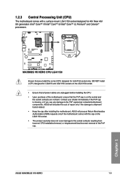
...™ i3, Pentium® and Celeron® processors. ASUS will process Return Merchandise Authorization (RMA) requests only if the motherboard comes with a surface mount LGA1150 socket designed for LGA1150 socket only. ASUS MAXIMUS VII HERO 1-9 Chapter 1 Ensure that the PnP cap is shipment/ ...transit-related. • Keep the cap after installing the motherboard. ASUS will shoulder the cost of the PnP cap. 1.2.3 Central Processing...
...™ i3, Pentium® and Celeron® processors. ASUS will process Return Merchandise Authorization (RMA) requests only if the motherboard comes with a surface mount LGA1150 socket designed for LGA1150 socket only. ASUS MAXIMUS VII HERO 1-9 Chapter 1 Ensure that the PnP cap is shipment/ ...transit-related. • Keep the cap after installing the motherboard. ASUS will shoulder the cost of the PnP cap. 1.2.3 Central Processing...
User Guide
Page 25
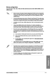
... system maps the total size of accessing information from a memory module. For optimal compatibility, we recommend that you are using a 32-bit Windows OS. Chapter 1 ASUS MAXIMUS VII HERO 1-11 b) Install a 64-bit Windows OS when you install 4GB or more efficient memory cooling system to Intel CPU spec, DIMM voltage below 1.65V is...
... system maps the total size of accessing information from a memory module. For optimal compatibility, we recommend that you are using a 32-bit Windows OS. Chapter 1 ASUS MAXIMUS VII HERO 1-11 b) Install a 64-bit Windows OS when you install 4GB or more efficient memory cooling system to Intel CPU spec, DIMM voltage below 1.65V is...

User Guide
Page 27
Timing DS - - 10-11-11-31 Voltage DIMM socket support (Optional) 2 4 1.65 • • Chapter 1 ASUS MAXIMUS VII HERO 1-13 Size Apacer Apacer Apacer CORSAIR G.SKILL GEIL KINGSTON 78.BAGFF.AFC0C(XMP) 78.BAGFR.AFD0C(XMP) 78.CAGFF.AFD0C(XMP) CMD16GX3M4A2666C11 (Ver5.12)(XMP) ...
Timing DS - - 10-11-11-31 Voltage DIMM socket support (Optional) 2 4 1.65 • • Chapter 1 ASUS MAXIMUS VII HERO 1-13 Size Apacer Apacer Apacer CORSAIR G.SKILL GEIL KINGSTON 78.BAGFF.AFC0C(XMP) 78.BAGFR.AFD0C(XMP) 78.CAGFF.AFD0C(XMP) CMD16GX3M4A2666C11 (Ver5.12)(XMP) ...

User Guide
Page 31
...; • • • • • • • • • • • • • • • • • • • (continued on the next page) Chapter 1 ASUS MAXIMUS VII HERO 1-17 DDR3 1800 MHz capability Vendors Part No. Timing G.SKILL F3-14400CL9D-4GBRL(XMP) 4GB (2x 2GB ) DS - - 9-9-9-24 Voltage DIMM socket support (Optional) 2 4 1.65...
...; • • • • • • • • • • • • • • • • • • • (continued on the next page) Chapter 1 ASUS MAXIMUS VII HERO 1-17 DDR3 1800 MHz capability Vendors Part No. Timing G.SKILL F3-14400CL9D-4GBRL(XMP) 4GB (2x 2GB ) DS - - 9-9-9-24 Voltage DIMM socket support (Optional) 2 4 1.65...

User Guide
Page 33
...; • - - - - 1333- 1.5 • • 9-9-9- 24 - 1.5 • • KINGSTON D2568JPUCPGGBU 11-11- - • • 11-28-1 Hynix H5TQ2G83CFRPBC - 1.5 • • (continued on the next page) Chapter 1 ASUS MAXIMUS VII HERO 1-19
...; • - - - - 1333- 1.5 • • 9-9-9- 24 - 1.5 • • KINGSTON D2568JPUCPGGBU 11-11- - • • 11-28-1 Hynix H5TQ2G83CFRPBC - 1.5 • • (continued on the next page) Chapter 1 ASUS MAXIMUS VII HERO 1-19

User Guide
Page 35
...; - • • 1.5 • • 1.5 • 1.5 • • - • • 1.5 • • 1.5 • • 1.5 • • 1.5 • • 1.5 • • (continued on the next page) Chapter 1 ASUS MAXIMUS VII HERO 1-21 N/A - SAMSUNG K4B1G0846F SAMSUNG K4B1G0846F(ECC) Micron D9KPT Micron D9KPT(ECC) SAMSUNG K4B1G0846F(ECC) Hynix H5TQ2G83AFR Hynix H5TQ2G83AFR(ECC) AMD 23EY4587MB3H AMD 23EY4587MB3H Apacer AM5D5808FEQSBG...
...; - • • 1.5 • • 1.5 • 1.5 • • - • • 1.5 • • 1.5 • • 1.5 • • 1.5 • • 1.5 • • (continued on the next page) Chapter 1 ASUS MAXIMUS VII HERO 1-21 N/A - SAMSUNG K4B1G0846F SAMSUNG K4B1G0846F(ECC) Micron D9KPT Micron D9KPT(ECC) SAMSUNG K4B1G0846F(ECC) Hynix H5TQ2G83AFR Hynix H5TQ2G83AFR(ECC) AMD 23EY4587MB3H AMD 23EY4587MB3H Apacer AM5D5808FEQSBG...

User Guide
Page 37
...SS/ DS Chip Brand Chip NO. Single-sided DS - settings in the BIOS for the hyper DIMM support. • Visit the ASUS website for better compatibility. (4) Supports four (4) modules inserted into slots A2 and B2 for the latest QVL. DDR3 1333 MHz capability ...8226;• - - •• - - •• 9 - •• 9-9-9-24 - •• 9-9-9-24 - •• - - •• - - •• - - •• Side(s): SS - Chapter 1 ASUS MAXIMUS VII HERO 1-23 Double-sided DIMM support: (1) Supports one pair of individual CPUs.
...SS/ DS Chip Brand Chip NO. Single-sided DS - settings in the BIOS for the hyper DIMM support. • Visit the ASUS website for better compatibility. (4) Supports four (4) modules inserted into slots A2 and B2 for the latest QVL. DDR3 1333 MHz capability ...8226;• - - •• - - •• 9 - •• 9-9-9-24 - •• 9-9-9-24 - •• - - •• - - •• - - •• Side(s): SS - Chapter 1 ASUS MAXIMUS VII HERO 1-23 Double-sided DIMM support: (1) Supports one pair of individual CPUs.
User Guide
Page 39
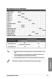
... slots are occupied. PCIe_x16/x8_1 slot switches to the motherboard connector labeled CHA_FAN1-4 when using multiple graphics cards for this motherboard A B C D E F G H PCIE_x16/x8_1 shared - - - - - - - Chapter 1 ASUS MAXIMUS VII HERO 1-25
... slots are occupied. PCIe_x16/x8_1 slot switches to the motherboard connector labeled CHA_FAN1-4 when using multiple graphics cards for this motherboard A B C D E F G H PCIE_x16/x8_1 shared - - - - - - - Chapter 1 ASUS MAXIMUS VII HERO 1-25
User Guide
Page 41
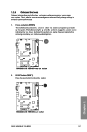
... system and unplug the power cable before removing or installing any motherboard component. 2. RESET button (RESET) Press the reset button to enhance system performance. 1. Chapter 1 ASUS MAXIMUS VII HERO 1-27 The button also lights up the system. 1.2.6 Onboard buttons Onboard buttons allow you to fine-tune performance when working on button that you to...
... system and unplug the power cable before removing or installing any motherboard component. 2. RESET button (RESET) Press the reset button to enhance system performance. 1. Chapter 1 ASUS MAXIMUS VII HERO 1-27 The button also lights up the system. 1.2.6 Onboard buttons Onboard buttons allow you to fine-tune performance when working on button that you to...

User Guide
Page 43
Clear CMOS button (CLR_CMOS) Press this button to clear the BIOS setup information only when the systems hangs due to the Software Support chapter of this button to activate the KeyBot feature. • The KeyBot feature supports USB keyboards only. • For more information about the KeyBot feature, refer to overclocking. 5. KeyBot button (KeyBot) Press this user guide. ASUS MAXIMUS VII HERO 1-29 Chapter 1 4.
Clear CMOS button (CLR_CMOS) Press this button to clear the BIOS setup information only when the systems hangs due to the Software Support chapter of this button to activate the KeyBot feature. • The KeyBot feature supports USB keyboards only. • For more information about the KeyBot feature, refer to overclocking. 5. KeyBot button (KeyBot) Press this user guide. ASUS MAXIMUS VII HERO 1-29 Chapter 1 4.

User Guide
Page 45
... indicate the hard disk activity. Hard Disk LED (HD_LED) The Hard Disk LED is being written into or read from the hard disk drive. Chapter 1 ASUS MAXIMUS VII HERO 1-31 If an error is found, the corresponding LED flashes until the problem is no hard disk drive connected to locate the root problem within...
... indicate the hard disk activity. Hard Disk LED (HD_LED) The Hard Disk LED is being written into or read from the hard disk drive. Chapter 1 ASUS MAXIMUS VII HERO 1-31 If an error is found, the corresponding LED flashes until the problem is no hard disk drive connected to locate the root problem within...

User Guide
Page 47
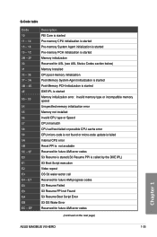
Chapter 1 ASUS MAXIMUS VII HERO 1-33 5. Refer to the Q-Code table on the following page for details. Q-Code LEDs The Q-Code LED design provides you with a 2-digit error code that displays the system status.
Chapter 1 ASUS MAXIMUS VII HERO 1-33 5. Refer to the Q-Code table on the following page for details. Q-Code LEDs The Q-Code LED design provides you with a 2-digit error code that displays the system status.
User Guide
Page 49
... System Agent initialization is started Pre-memory PCH initialization is started Memory initialization Reserved for future AMI error codes (continued on the next page) Chapter 1 ASUS MAXIMUS VII HERO 1-35 Invalid memory type or incompatible memory speed Unspecified memory initialization error Memory not installed Invalid CPU type or Speed CPU mismatch CPU self test...
... System Agent initialization is started Pre-memory PCH initialization is started Memory initialization Reserved for future AMI error codes (continued on the next page) Chapter 1 ASUS MAXIMUS VII HERO 1-35 Invalid memory type or incompatible memory speed Unspecified memory initialization error Memory not installed Invalid CPU type or Speed CPU mismatch CPU self test...

User Guide
Page 51
... Runtime Set Virtual Address MAP End Legacy Option ROM Initialization System Reset USB hot plug PCI bus hot plug (continued on the next page) Chapter 1 ASUS MAXIMUS VII HERO 1-37
... Runtime Set Virtual Address MAP End Legacy Option ROM Initialization System Reset USB hot plug PCI bus hot plug (continued on the next page) Chapter 1 ASUS MAXIMUS VII HERO 1-37

User Guide
Page 53
... for details. • Before creating a RAID set, refer to section RAID configurations or the manual bundled in the BIOS to section SATA Configuration for details. ASUS MAXIMUS VII HERO 1-39 Intel® Z97 Serial ATA 6 Gb/s connectors (7-pin SATA6G_1-6 [red]) These connectors connect to Serial ATA 6 Gb/s hard disk drives via Serial ATA 6 Gb...
... for details. • Before creating a RAID set, refer to section RAID configurations or the manual bundled in the BIOS to section SATA Configuration for details. ASUS MAXIMUS VII HERO 1-39 Intel® Z97 Serial ATA 6 Gb/s connectors (7-pin SATA6G_1-6 [red]) These connectors connect to Serial ATA 6 Gb/s hard disk drives via Serial ATA 6 Gb...

User Guide
Page 55
These USB connectors comply with ROG extension (ROG_EXT) port. You can connect the front panel USB cable to the ASUS Q-Connector (USB) first, and then install the Q-Connector (USB) to the USB connector onboard if your chassis supports front panel USB ports. 1 x USB 2.0 ports (USB13.... Connect the USB module cable to any of the system chassis. 4. Doing so will damage the motherboard! USB 2.0 connectors (10-1 pin USB13, USB1112; Chapter 1 ASUS MAXIMUS VII HERO 1-41 USB910) These connectors are for USB 2.0 ports. Never connect a 1394 cable to 480 MBps connection speed.
These USB connectors comply with ROG extension (ROG_EXT) port. You can connect the front panel USB cable to the ASUS Q-Connector (USB) first, and then install the Q-Connector (USB) to the USB connector onboard if your chassis supports front panel USB ports. 1 x USB 2.0 ports (USB13.... Connect the USB module cable to any of the system chassis. 4. Doing so will damage the motherboard! USB 2.0 connectors (10-1 pin USB13, USB1112; Chapter 1 ASUS MAXIMUS VII HERO 1-41 USB910) These connectors are for USB 2.0 ports. Never connect a 1394 cable to 480 MBps connection speed.


