Troubleshooting Guide
Page 4
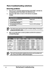
...devices / error Graphics card Memory Fan error or CPU overheating Turn off no display stopped Boot failure/ on no display stopped no screen on no display working display on no display working Cannot enter on display working OS/other on display working Beep no beep no beep no beep beeping beeping no beep no beep Error message Solution Page no display one 5 no display two 6 no display two 6 no display two 6 display three 6 display three 6 no error message three 6 After performing all the devices are properly installed. Indicators Error Power LED...
...devices / error Graphics card Memory Fan error or CPU overheating Turn off no display stopped Boot failure/ on no display stopped no screen on no display working display on no display working Cannot enter on display working OS/other on display working Beep no beep no beep no beep beeping beeping no beep no beep Error message Solution Page no display one 5 no display two 6 no display two 6 no display two 6 display three 6 display three 6 no error message three 6 After performing all the devices are properly installed. Indicators Error Power LED...
Troubleshooting Guide
Page 6
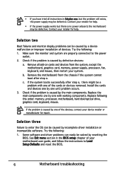
...: memory, processor, motherboard, hard disk/optical drive, graphics card, keyboard, mouse. Check if the problem is no power onboard, the motherboard may be defective. Solution three Failure to enter the OS can be caused by the main components. Solution two Boot failures and monitor display problems can easily be solved by defective devices: a. If the system boots successfully after step a. Replace the main components one , but there is caused by incomplete driver installation or incompatible software. See Exit menu...
...: memory, processor, motherboard, hard disk/optical drive, graphics card, keyboard, mouse. Check if the problem is no power onboard, the motherboard may be defective. Solution three Failure to enter the OS can be caused by the main components. Solution two Boot failures and monitor display problems can easily be solved by defective devices: a. If the system boots successfully after step a. Replace the main components one , but there is caused by incomplete driver installation or incompatible software. See Exit menu...

User Guide
Page 2
... attachments such as the corresponding binary/object code. All Rights Reserved. SPECIFICATIONS AND INFORMATION CONTAINED IN THIS MANUAL ARE FURNISHED FOR INFORMATIONAL USE ONLY, AND ARE SUBJECT TO CHANGE AT ANY TIME WITHOUT NOTICE, AND SHOULD NOT BE CONSTRUED AS A COMMITMENT BY ASUS. Offer to infringe. Product warranty or service will be reproduced, transmitted, transcribed, stored in...
... attachments such as the corresponding binary/object code. All Rights Reserved. SPECIFICATIONS AND INFORMATION CONTAINED IN THIS MANUAL ARE FURNISHED FOR INFORMATIONAL USE ONLY, AND ARE SUBJECT TO CHANGE AT ANY TIME WITHOUT NOTICE, AND SHOULD NOT BE CONSTRUED AS A COMMITMENT BY ASUS. Offer to infringe. Product warranty or service will be reproduced, transmitted, transcribed, stored in...

User Guide
Page 5
...DVD 4-1 4.2.2 Obtaining the software manuals 4-2 4.3 Software information 4-3 4.4 AI Suite 3...4-3 4.5 Dual Intelligent Processors 5 4-6 4.6 ROG Audio features 4-22 4.7 Sonic Radar II 4-28 4.8 GameFirst III 4-30 4.9 KeyBot...4-33 4.10 ASUS Media Streamer 4-35 4.11 ASUS Disk Unlocker 4-37 4.12 RAMDisk...4-38 4.13 MemTweakIt 4-41 4.14 ROG CPU-Z 4-43 Chapter 5: RAID support 5.1 RAID configurations 5-1 5.1.1 RAID definitions 5-1 5.1.2 Installing Serial ATA hard disks 5-2 5.1.3 Setting the RAID item in BIOS 5-2 5.1.4 Intel® Rapid Storage Technology Option ROM...
...DVD 4-1 4.2.2 Obtaining the software manuals 4-2 4.3 Software information 4-3 4.4 AI Suite 3...4-3 4.5 Dual Intelligent Processors 5 4-6 4.6 ROG Audio features 4-22 4.7 Sonic Radar II 4-28 4.8 GameFirst III 4-30 4.9 KeyBot...4-33 4.10 ASUS Media Streamer 4-35 4.11 ASUS Disk Unlocker 4-37 4.12 RAMDisk...4-38 4.13 MemTweakIt 4-41 4.14 ROG CPU-Z 4-43 Chapter 5: RAID support 5.1 RAID configurations 5-1 5.1.1 RAID definitions 5-1 5.1.2 Installing Serial ATA hard disks 5-2 5.1.3 Setting the RAID item in BIOS 5-2 5.1.4 Intel® Rapid Storage Technology Option ROM...
User Guide
Page 15
... SLI®/ CrossFireX™ graphics cards for faster data retrieval. It provides an optimal graphics performance, unprecedented data speed and seamless transition with its complete backward compatibility to six USB 3.0 ports, six SATA 6 Gb/s ports, and M.2 support for an unrivalled gaming performance. Intel® Z97 Express Chipset Intel® Z97 Express Chipset is the PCIe bus standard that supports the LGA1150 socket for Intel® integrated graphics performance. It also enables...
... SLI®/ CrossFireX™ graphics cards for faster data retrieval. It provides an optimal graphics performance, unprecedented data speed and seamless transition with its complete backward compatibility to six USB 3.0 ports, six SATA 6 Gb/s ports, and M.2 support for an unrivalled gaming performance. Intel® Z97 Express Chipset Intel® Z97 Express Chipset is the PCIe bus standard that supports the LGA1150 socket for Intel® integrated graphics performance. It also enables...
User Guide
Page 19
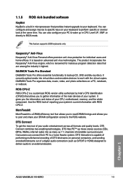
... your audio entertainment across all formats and quality levels, DTS Connect combines two enabling technologies, DTS Neo:PC™ up in microprocessor that allows you to gather information of the main devices of reporting your DRAM configuration scores to the ROG website. 1.1.5 ROG rich bundled software KeyBot KeyBot is a built-in CPU Level UP, XMP, or directly to BIOS mode. This feature supports USB keyboards...
... your audio entertainment across all formats and quality levels, DTS Connect combines two enabling technologies, DTS Neo:PC™ up in microprocessor that allows you to gather information of the main devices of reporting your DRAM configuration scores to the ROG website. 1.1.5 ROG rich bundled software KeyBot KeyBot is a built-in CPU Level UP, XMP, or directly to BIOS mode. This feature supports USB keyboards...

User Guide
Page 51
... is started SCSI Reset SCSI Detect SCSI Enable Setup Verifying Password Start of Setup Reserved for ASL (see ASL Status Codes section below) Setup Input Wait Reserved for ASL (see ASL Status Codes section below) Ready To Boot event Legacy Boot event Exit Boot Services event Runtime Set Virtual Address MAP Begin Runtime Set Virtual Address MAP End Legacy Option ROM Initialization System Reset USB hot plug PCI bus hot plug (continued on the next page) Chapter 1 ASUS MAXIMUS VII HERO 1-37
... is started SCSI Reset SCSI Detect SCSI Enable Setup Verifying Password Start of Setup Reserved for ASL (see ASL Status Codes section below) Setup Input Wait Reserved for ASL (see ASL Status Codes section below) Ready To Boot event Legacy Boot event Exit Boot Services event Runtime Set Virtual Address MAP Begin Runtime Set Virtual Address MAP End Legacy Option ROM Initialization System Reset USB hot plug PCI bus hot plug (continued on the next page) Chapter 1 ASUS MAXIMUS VII HERO 1-37

User Guide
Page 54
...; Serial ATA 6 Gb/s connectors (7-pin SATA6G_E1/2 [red]) These connectors connect to fully use the USB 3.0 ports under Windows® 7, Windows® 8, and Windows® 8.1. • The plugged USB 3.0 device may run on xHCI or EHCI mode depending on xHCI specification. With an installed USB 3.0 module, you can enjoy all the benefits of USB 3.0 including faster data transfer speeds of up to connect a USB 3.0 module for USB-chargeable devices, optimized power efficiency, and backward compatibility with USB 2.0. We...
...; Serial ATA 6 Gb/s connectors (7-pin SATA6G_E1/2 [red]) These connectors connect to fully use the USB 3.0 ports under Windows® 7, Windows® 8, and Windows® 8.1. • The plugged USB 3.0 device may run on xHCI or EHCI mode depending on xHCI specification. With an installed USB 3.0 module, you can enjoy all the benefits of USB 3.0 including faster data transfer speeds of up to connect a USB 3.0 module for USB-chargeable devices, optimized power efficiency, and backward compatibility with USB 2.0. We...
User Guide
Page 112
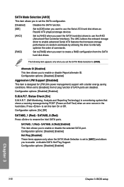
... Serial ATA hard disk drives as Parallel ATA physical storage devices. [AHCI] Set to [AHCI] when you set the SATA Mode Selection to [RAID]. SATA6G_6 (Red) Press to enable advanced Serial ATA features that shows a warning message during POST (Power-on random workloads by allowing the drive to internally optimize the order of SATA ports are disabled. Alternate ID [Disabled] This item allows you want the SATA hard disk drives to create a RAID configuration from the SATA hard disk drives. Configuration options: [Disabled] [Enabled] S.M.A.R.T. The AHCI allows the onboard storage driver...
... Serial ATA hard disk drives as Parallel ATA physical storage devices. [AHCI] Set to [AHCI] when you set the SATA Mode Selection to [RAID]. SATA6G_6 (Red) Press to enable advanced Serial ATA features that shows a warning message during POST (Power-on random workloads by allowing the drive to internally optimize the order of SATA ports are disabled. Alternate ID [Disabled] This item allows you want the SATA hard disk drives to create a RAID configuration from the SATA hard disk drives. Configuration options: [Disabled] [Enabled] S.M.A.R.T. The AHCI allows the onboard storage driver...
User Guide
Page 114
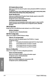
... Render Standby support to DVMT 5.0 used by the CPU graphics. Configuration options: [Enabled] [Disabled] Memory Remap [Enabled] Allows you to enable remapping the memory above 4GB. Memory Configuration Allows you to configure the memory configuration parameters. Memory Scrambler [Enabled] Allows you to run at PCI-E 2.0 speed. Configuration options: [Enabled] [Disabled] Chapter 3 3-34 Chapter 3: BIOS setup Configuration options: [Disabled] [Enabled] DMI Configuration Enable this item for the DMI (Direct media interface) to configure the NB PCI Express settings. DMI Gen...
... Render Standby support to DVMT 5.0 used by the CPU graphics. Configuration options: [Enabled] [Disabled] Memory Remap [Enabled] Allows you to enable remapping the memory above 4GB. Memory Configuration Allows you to configure the memory configuration parameters. Memory Scrambler [Enabled] Allows you to run at PCI-E 2.0 speed. Configuration options: [Enabled] [Disabled] Chapter 3 3-34 Chapter 3: BIOS setup Configuration options: [Disabled] [Enabled] DMI Configuration Enable this item for the DMI (Direct media interface) to configure the NB PCI Express settings. DMI Gen...

User Guide
Page 115
... USB controller legacy mode is set to [Disabled] by default for the EHCI (enhanced host controller interface) support by BIOS for the BIOS setup program. If no USB device is installed in operating systems. [Disabled] [Enabled] Support EHCI by EHCI drivers for operating systems with EHCI support. Refer to enable or disable the individual USB ports. USB Single Port Control Allows you to change the USB-related features. ASUS MAXIMUS VII HERO 3-35 Chapter 3 3.6.5 USB Configuration The items in boot devices list. [Enabled] Enables the support for USB devices on legacy operating...
... USB controller legacy mode is set to [Disabled] by default for the EHCI (enhanced host controller interface) support by BIOS for the BIOS setup program. If no USB device is installed in operating systems. [Disabled] [Enabled] Support EHCI by EHCI drivers for operating systems with EHCI support. Refer to enable or disable the individual USB ports. USB Single Port Control Allows you to change the USB-related features. ASUS MAXIMUS VII HERO 3-35 Chapter 3 3.6.5 USB Configuration The items in boot devices list. [Enabled] Enables the support for USB devices on legacy operating...
User Guide
Page 117
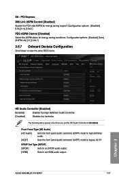
...SPDIF audio output. [HDMI] Sets to view the other BIOS items. Chapter 3 HD Audio Controller [Enabled] [Enabled] Enables the High Definition Audio Controller. [Disabled] Disables the controller. Configuration options: [Disabled] [L0s] [L1s] [L0sL1] PEG ASPM Control [Disabled] Select the ASPM states for energy saving support. Configuration options: [Disabled] [Auto] [ASPM L0s] [L1] [L0sL1] 3.6.7 Onboard Devices Configuration Scroll down to an HDMI audio output. PCI Express DMI Link ASPM Control [Disabled] Enable the PCH side ASPM for energy saving conditions. ASUS MAXIMUS VII HERO...
...SPDIF audio output. [HDMI] Sets to view the other BIOS items. Chapter 3 HD Audio Controller [Enabled] [Enabled] Enables the High Definition Audio Controller. [Disabled] Disables the controller. Configuration options: [Disabled] [L0s] [L1s] [L0sL1] PEG ASPM Control [Disabled] Select the ASPM states for energy saving support. Configuration options: [Disabled] [Auto] [ASPM L0s] [L1] [L0sL1] 3.6.7 Onboard Devices Configuration Scroll down to an HDMI audio output. PCI Express DMI Link ASPM Control [Disabled] Enable the PCH side ASPM for energy saving conditions. ASUS MAXIMUS VII HERO...
User Guide
Page 119
ASUS MAXIMUS VII HERO 3-39 Chapter 3 When set to [Enabled], all other installed PCIE LAN devices. [Enabled] Enables the PCIE/PCI devices to generate a wake-on -LAN feature of the PCIE LAN devices. Configuration options: [Disabled] [Enabled(S4+S5] [Enabled(S5)] Restore AC Power Loss [Power Off] [Power Off] The system goes into OFF state after an AC power loss. [Power On] The system goes into ON state after an AC power loss. [Last State] The system goes into either OFF or...
ASUS MAXIMUS VII HERO 3-39 Chapter 3 When set to [Enabled], all other installed PCIE LAN devices. [Enabled] Enables the PCIE/PCI devices to generate a wake-on -LAN feature of the PCIE LAN devices. Configuration options: [Disabled] [Enabled(S4+S5] [Enabled(S5)] Restore AC Power Loss [Power Off] [Power Off] The system goes into OFF state after an AC power loss. [Power On] The system goes into ON state after an AC power loss. [Last State] The system goes into either OFF or...
User Guide
Page 125
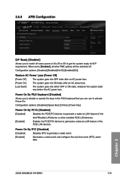
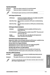
... hard drives connected to SATA ports are detected during POST. USB Support [Partial Initialization] [Disabled] [Full Initialization] [Partial Initialization] All USB devices will extend the POST time. This process will not be available during POST. Chapter 3 ASUS MAXIMUS VII HERO 3-45 Fast Boot [Enabled] [Disabled] Allows your system to accelerate the boot speed. The following items appear only when you to disable or have to connect the 2-pin connector of the PS/2 devices' availability during POST. Configuration options: [Auto] [Disabled] [Full Initialization] Network...
... hard drives connected to SATA ports are detected during POST. USB Support [Partial Initialization] [Disabled] [Full Initialization] [Partial Initialization] All USB devices will extend the POST time. This process will not be available during POST. Chapter 3 ASUS MAXIMUS VII HERO 3-45 Fast Boot [Enabled] [Disabled] Allows your system to accelerate the boot speed. The following items appear only when you to disable or have to connect the 2-pin connector of the PS/2 devices' availability during POST. Configuration options: [Auto] [Disabled] [Full Initialization] Network...

User Guide
Page 136
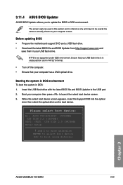
... environment using the motherboard support DVD and a USB flash disk drive. 3.11.1 EZ Update The EZ Update is a utility that comes with the motherboard package. • Refer to update your BIOS when necessary. Carefully follow the instructions in this motherboard. Chapter 3 3-56 Chapter 3: BIOS setup However, BIOS updating is potentially risky. 3.11 Updating BIOS The ASUS website publishes the latest BIOS versions to update the motherboard BIOS in Windows® environment. • EZ Update requires an Internet connection either through a network or...
... environment using the motherboard support DVD and a USB flash disk drive. 3.11.1 EZ Update The EZ Update is a utility that comes with the motherboard package. • Refer to update your BIOS when necessary. Carefully follow the instructions in this motherboard. Chapter 3 3-56 Chapter 3: BIOS setup However, BIOS updating is potentially risky. 3.11 Updating BIOS The ASUS website publishes the latest BIOS versions to update the motherboard BIOS in Windows® environment. • EZ Update requires an Internet connection either through a network or...
User Guide
Page 138
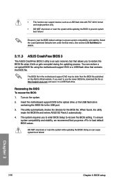
... Exit Menu for the BIOS file. The BIOS file in the motherboard support DVD may be older than the BIOS file published on the system. 2. When found, the utility reads the BIOS file and enters ASUS EZ Flash 2 automatically. 4. Ensure to load the BIOS default settings to the USB port. 3. Turn on the ASUS official website. The utility automatically checks the devices for details. 3.11.3 ASUS CrashFree BIOS 3 The ASUS CrashFree BIOS 3 utility is an auto recovery tool that contains the BIOS file. Recovering the BIOS...
... Exit Menu for the BIOS file. The BIOS file in the motherboard support DVD may be older than the BIOS file published on the system. 2. When found, the utility reads the BIOS file and enters ASUS EZ Flash 2 automatically. 4. Ensure to load the BIOS default settings to the USB port. 3. Turn on the ASUS official website. The utility automatically checks the devices for details. 3.11.3 ASUS CrashFree BIOS 3 The ASUS CrashFree BIOS 3 utility is an auto recovery tool that contains the BIOS file. Recovering the BIOS...
User Guide
Page 139
... select boot device: E1: ASUS DVD-E818A6T (4069MB) USB DISK 2.0 (3824MB) UEFI: (FAT) USB DISK 2.0 (3824MB) Enter Setup and to move selection ENTER to select boot device ESC to update the BIOS in DOS environment. 3.11.4 ASUS BIOS Updater ASUS BIOS Updater allows you to boot using defaults Chapter 3 ASUS MAXIMUS VII HERO 3-59 Booting the system in DOS environment To boot the system in your computer screen. Ensure that your USB flash drive is not supported under DOS environment. Boot your computer has a DVD optical drive...
... select boot device: E1: ASUS DVD-E818A6T (4069MB) USB DISK 2.0 (3824MB) UEFI: (FAT) USB DISK 2.0 (3824MB) Enter Setup and to move selection ENTER to select boot device ESC to update the BIOS in DOS environment. 3.11.4 ASUS BIOS Updater ASUS BIOS Updater allows you to boot using defaults Chapter 3 ASUS MAXIMUS VII HERO 3-59 Booting the system in DOS environment To boot the system in your computer screen. Ensure that your USB flash drive is not supported under DOS environment. Boot your computer has a DVD optical drive...

User Guide
Page 188
... the BIOS Setup before creating RAID sets using SATA HDDs. To do this: 1. Go to [RAID Mode]. 4. 5.1.2 Installing Serial ATA hard disks The motherboard supports Serial ATA hard disk drives. Set the SATA Mode item to the Advanced menu > SATA Configuration, and then press . 3. Install the SATA hard disks into the drive bays. 2. Refer to RAID mode, all SATA ports run at RAID mode together. For optimal performance, install identical drives of the same model and capacity when creating a disk array. Connect the SATA signal cables. 3. Connect a SATA power cable to the power connector...
... the BIOS Setup before creating RAID sets using SATA HDDs. To do this: 1. Go to [RAID Mode]. 4. 5.1.2 Installing Serial ATA hard disks The motherboard supports Serial ATA hard disk drives. Set the SATA Mode item to the Advanced menu > SATA Configuration, and then press . 3. Install the SATA hard disks into the drive bays. 2. Refer to RAID mode, all SATA ports run at RAID mode together. For optimal performance, install identical drives of the same model and capacity when creating a disk array. Connect the SATA signal cables. 3. Connect a SATA power cable to the power connector...
User Guide
Page 193
... when installing a Windows® operating system on a hard disk drive that is included in a RAID set. Boot your computer. 2. Insert a formatted floppy disk into the optical drive. 5. Insert the support DVD into the USB floppy disk drive, then press . 8. Set the optical drive as the primary boot device. 4. Chapter 5 ASUS MAXIMUS VII HERO 5-7 When the Make Disk menu appears, press to create a RAID driver disk. 7. From the utility main menu, select 5. The motherboard does not provide a floppy drive connector. Exiting the Intel® Rapid Storage Technology Option ROM utility To...
... when installing a Windows® operating system on a hard disk drive that is included in a RAID set. Boot your computer. 2. Insert a formatted floppy disk into the optical drive. 5. Insert the support DVD into the USB floppy disk drive, then press . 8. Set the optical drive as the primary boot device. 4. Chapter 5 ASUS MAXIMUS VII HERO 5-7 When the Make Disk menu appears, press to create a RAID driver disk. 7. From the utility main menu, select 5. The motherboard does not provide a floppy drive connector. Exiting the Intel® Rapid Storage Technology Option ROM utility To...

User Guide
Page 194
... motherboard support DVD into the optical drive, and then click Browse. 3. Before loading the RAID driver from the support DVD to the USB flash drive. Chapter 5 5-8 Chapter 5: RAID support Follow the succeeding screen instructions to create a RAID driver disk. 5. Insert the USB flash drive with RAID driver into the USB port or the support DVD into the optical drive. 4. Go to the Make Disk menu, and then click Intel AHCI/RAID Driver Disk to complete the process. Select USB floppy disk drive as the destination disk. 6. During the OS installation, click Load Driver...
... motherboard support DVD into the optical drive, and then click Browse. 3. Before loading the RAID driver from the support DVD to the USB flash drive. Chapter 5 5-8 Chapter 5: RAID support Follow the succeeding screen instructions to create a RAID driver disk. 5. Insert the USB flash drive with RAID driver into the USB port or the support DVD into the optical drive. 4. Go to the Make Disk menu, and then click Intel AHCI/RAID Driver Disk to complete the process. Select USB floppy disk drive as the destination disk. 6. During the OS installation, click Load Driver...


