

User Guide
Page 15
... faster data retrieval. We believe in making statements and we welcome the best gamers to 2-WAY Quad-GPU SLI® or CrossFireX™ configuration. Chapter 1 ASUS MAXIMUS VII GENE 1-1 It provides great graphics and system performance with its GPU, dual-channel DDR3 memory slots, and PCI Express 2.0/3.0 expansion slots. It natively supports up to...
... faster data retrieval. We believe in making statements and we welcome the best gamers to 2-WAY Quad-GPU SLI® or CrossFireX™ configuration. Chapter 1 ASUS MAXIMUS VII GENE 1-1 It provides great graphics and system performance with its GPU, dual-channel DDR3 memory slots, and PCI Express 2.0/3.0 expansion slots. It natively supports up to...
User Guide
Page 17
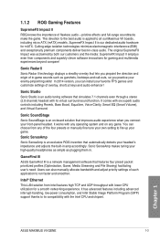
... advanced interrupt-handling, low-power consumption, and Intel Stable Image Platform Program (SIPP) support thanks to its virtual surround-sound function. Chapter 1 ASUS MAXIMUS VII GENE 1-3 Sonic SenseAmp Sonic SenseAmp is an on any of the four presets or manually fine tune your own setting to all our... Maximus VII boards, including micro ATX (mATX) models. In 2014 version, you practice your enemy-pinpointing skills! You can also manually allocate bandwidth and ...
... advanced interrupt-handling, low-power consumption, and Intel Stable Image Platform Program (SIPP) support thanks to its virtual surround-sound function. Chapter 1 ASUS MAXIMUS VII GENE 1-3 Sonic SenseAmp Sonic SenseAmp is an on any of the four presets or manually fine tune your own setting to all our... Maximus VII boards, including micro ATX (mATX) models. In 2014 version, you practice your enemy-pinpointing skills! You can also manually allocate bandwidth and ...

User Guide
Page 19
... Neo:PC™ up in microprocessor that allows you to read DRAM timings and allows you the information and status of incredible surround sound. Chapter 1 ASUS MAXIMUS VII GENE 1-5 This feature supports USB keyboards only. It is based on a PC, notebook, or netbook. DAEMON Tools Pro Standard DAEMON Tools Pro offers essential functionality to...
... Neo:PC™ up in microprocessor that allows you to read DRAM timings and allows you the information and status of incredible surround sound. Chapter 1 ASUS MAXIMUS VII GENE 1-5 This feature supports USB keyboards only. It is based on a PC, notebook, or netbook. DAEMON Tools Pro Standard DAEMON Tools Pro offers essential functionality to...

User Guide
Page 21
ASUS MAXIMUS VII GENE 1-7 1.2.2 Motherboard layout Chapter 1 Refer to Internal connectors and Rear I/O connection for more information about rear panel connectors and internal connectors.
ASUS MAXIMUS VII GENE 1-7 1.2.2 Motherboard layout Chapter 1 Refer to Internal connectors and Rear I/O connection for more information about rear panel connectors and internal connectors.
User Guide
Page 23
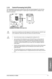
... to the socket contacts resulting from incorrect CPU installation/removal, or misplacement/loss/incorrect removal of the PnP cap. Chapter 1 ASUS MAXIMUS VII GENE 1-9 Contact your retailer immediately if the PnP cap is on the socket and the socket contacts are unplugged before installing the ...8482; i5/ Intel® Core™ i3, Pentium®, and Celeron® processors Ensure that all power cables are not bent. ASUS will process Return Merchandise Authorization (RMA) requests only if the motherboard comes with a surface mount LGA1150 socket designed for LGA1150 socket only....
... to the socket contacts resulting from incorrect CPU installation/removal, or misplacement/loss/incorrect removal of the PnP cap. Chapter 1 ASUS MAXIMUS VII GENE 1-9 Contact your retailer immediately if the PnP cap is on the socket and the socket contacts are unplugged before installing the ...8482; i5/ Intel® Core™ i3, Pentium®, and Celeron® processors Ensure that all power cables are not bent. ASUS will process Return Merchandise Authorization (RMA) requests only if the motherboard comes with a surface mount LGA1150 socket designed for LGA1150 socket only....
User Guide
Page 25
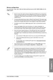
... and non‑ECC DDR3 DIMMs into the DIMM sockets. • Memory module with the same CAS latency. Any excess memory from a memory module. Chapter 1 ASUS MAXIMUS VII GENE 1-11
... and non‑ECC DDR3 DIMMs into the DIMM sockets. • Memory module with the same CAS latency. Any excess memory from a memory module. Chapter 1 ASUS MAXIMUS VII GENE 1-11

User Guide
Page 27
... • 13-32 DDR3 2500 MHz capability Vendors Part No. Timing DS - - 10-11-11-31 Voltage DIMM socket support (Optional) 2 4 1.65 • • Chapter 1 ASUS MAXIMUS VII GENE 1-13 DDR3 2666 MHz capability Vendors Part No. Size G.SKILL F3-20000CL10Q-16GBZHD(XMP) 16GB (4x 4GB) SS/ DS Chip Brand Chip NO. Size Apacer...
... • 13-32 DDR3 2500 MHz capability Vendors Part No. Timing DS - - 10-11-11-31 Voltage DIMM socket support (Optional) 2 4 1.65 • • Chapter 1 ASUS MAXIMUS VII GENE 1-13 DDR3 2666 MHz capability Vendors Part No. Size G.SKILL F3-20000CL10Q-16GBZHD(XMP) 16GB (4x 4GB) SS/ DS Chip Brand Chip NO. Size Apacer...

User Guide
Page 31
...; • • • • • • • • • • • • • • • • • • • (continued on the next page) Chapter 1 ASUS MAXIMUS VII GENE 1-17
...; • • • • • • • • • • • • • • • • • • • (continued on the next page) Chapter 1 ASUS MAXIMUS VII GENE 1-17

User Guide
Page 33
...; • - - - - 1333- 1.5 • • 9-9-9- 24 - 1.5 • • KINGSTON D2568JPUCPGGBU 11-11- - • • 11-28-1 Hynix H5TQ2G83CFRPBC - 1.5 • • (continued on the next page) Chapter 1 ASUS MAXIMUS VII GENE 1-19 DDR3 1600 MHz capability Vendors Part No.
...; • - - - - 1333- 1.5 • • 9-9-9- 24 - 1.5 • • KINGSTON D2568JPUCPGGBU 11-11- - • • 11-28-1 Hynix H5TQ2G83CFRPBC - 1.5 • • (continued on the next page) Chapter 1 ASUS MAXIMUS VII GENE 1-19 DDR3 1600 MHz capability Vendors Part No.

User Guide
Page 35
...; • • • • • • • • • • • • • • • • • • • (continued on the next page) Chapter 1 ASUS MAXIMUS VII GENE 1-21 N/A - Size SS/ DS ACTICA ACT1GHU64B8F1333S 1GB SS ACTICA ACT1GHU72C8G1333S 1GB SS ACTICA ACT2GHU64B8G1333M 2GB DS ACTICA ACT2GHU72D8G1333M 2GB DS ACTICA ACT2GHU72D8G1333S 2GB DS ACTICA...
...; • • • • • • • • • • • • • • • • • • • (continued on the next page) Chapter 1 ASUS MAXIMUS VII GENE 1-21 N/A - Size SS/ DS ACTICA ACT1GHU64B8F1333S 1GB SS ACTICA ACT1GHU72C8G1333S 1GB SS ACTICA ACT2GHU64B8G1333M 2GB DS ACTICA ACT2GHU72D8G1333M 2GB DS ACTICA ACT2GHU72D8G1333S 2GB DS ACTICA...

User Guide
Page 37
...into slots A2 and B2 for the latest QVL. Patriot RiDATA RiDATA SAMSUNG NANYA S-POWER S-POWER S-POWER Team Transcend MICRON - Chapter 1 ASUS MAXIMUS VII GENE 1-23 Single-sided DS - Load the X.M.P. Double-sided DIMM support: (1) Supports one (1) module inserted into either the red slots or... the black slots as two pairs of Dual-channel memory configuration. • ASUS exclusively provides hyper DIMM support function. • Hyper DIMM support is subject to the physical characteristics of Dual-channel memory configuration. ...
...into slots A2 and B2 for the latest QVL. Patriot RiDATA RiDATA SAMSUNG NANYA S-POWER S-POWER S-POWER Team Transcend MICRON - Chapter 1 ASUS MAXIMUS VII GENE 1-23 Single-sided DS - Load the X.M.P. Double-sided DIMM support: (1) Supports one (1) module inserted into either the red slots or... the black slots as two pairs of Dual-channel memory configuration. • ASUS exclusively provides hyper DIMM support function. • Hyper DIMM support is subject to the physical characteristics of Dual-channel memory configuration. ...

User Guide
Page 39
I.G.F.X shared - - High Definition Audio - - - ASmMedia SATA 6G Storage Controller - - - shared - shared - XHCI (USB 3.0) - - - ASmMedia USB 3.0 Controller shared - - shared - - - - - Chapter 1 ASUS MAXIMUS VII GENE 1-25 shared - SATA #1 - shared - - - - - - - - - SATA #0 - shared - - VGA Configuration Single VGA/PCIe card Dual VGA/PCIe card PCIe operating mode PCIe_x16/x8_1 x16 (Recommend for single ...
I.G.F.X shared - - High Definition Audio - - - ASmMedia SATA 6G Storage Controller - - - shared - shared - XHCI (USB 3.0) - - - ASmMedia USB 3.0 Controller shared - - shared - - - - - Chapter 1 ASUS MAXIMUS VII GENE 1-25 shared - SATA #1 - shared - - - - - - - - - SATA #0 - shared - - VGA Configuration Single VGA/PCIe card Dual VGA/PCIe card PCIe operating mode PCIe_x16/x8_1 x16 (Recommend for single ...

User Guide
Page 41
... and gamers who continually change settings to reboot the system. Power-on button (START) The motherboard comes with a power-on a bare or opencase system. Chapter 1 ASUS MAXIMUS VII GENE 1-27 1.2.6 Onboard buttons Onboard buttons allow you should shut down the system and unplug the power cable before removing or installing any motherboard component. 2.
... and gamers who continually change settings to reboot the system. Power-on button (START) The motherboard comes with a power-on a bare or opencase system. Chapter 1 ASUS MAXIMUS VII GENE 1-27 1.2.6 Onboard buttons Onboard buttons allow you should shut down the system and unplug the power cable before removing or installing any motherboard component. 2.

User Guide
Page 43
.... Sonic SoundStage button (SOUNDSTAGE) Press this user guide. Chapter 1 • The debug code on the designated USB port. KeyBot button (KEYBOT) Press this user guide. 5. ASUS MAXIMUS VII GENE 1-29 4. There are four presets that have been implemented: (01)FPS, (02)Racing, (03)Fighting, (04)Sports, and (dE)default. • For more information about...
.... Sonic SoundStage button (SOUNDSTAGE) Press this user guide. Chapter 1 • The debug code on the designated USB port. KeyBot button (KEYBOT) Press this user guide. 5. ASUS MAXIMUS VII GENE 1-29 4. There are four presets that have been implemented: (01)FPS, (02)Racing, (03)Fighting, (04)Sports, and (dE)default. • For more information about...

User Guide
Page 45
USB BIOS Flashback LED (FLBK_LED) This LED flashes when you activate the KeyBot function from the KeyBot software. 4. For more information on how to update the BIOS, refer to Chapter 2 of this user guide. ASUS MAXIMUS VII GENE 1-31 Chapter 1 KeyBot LED (KEYBOT_LED) This LED lights up when KeyBot function is activated when the onboard KeyBot button is pressed or when you press the ROG Connect button for BIOS update. 3.
USB BIOS Flashback LED (FLBK_LED) This LED flashes when you activate the KeyBot function from the KeyBot software. 4. For more information on how to update the BIOS, refer to Chapter 2 of this user guide. ASUS MAXIMUS VII GENE 1-31 Chapter 1 KeyBot LED (KEYBOT_LED) This LED lights up when KeyBot function is activated when the onboard KeyBot button is pressed or when you press the ROG Connect button for BIOS update. 3.

User Guide
Page 47
... - 18 19 - 1C 2B - 2F 30 31 32 - 36 37 - 3A 3B - 3E 4F 50 - 53 Description Not used Power on the next page) Chapter 1 ASUS MAXIMUS VII GENE 1-33 Reset type detection (soft/hard).
... - 18 19 - 1C 2B - 2F 30 31 32 - 36 37 - 3A 3B - 3E 4F 50 - 53 Description Not used Power on the next page) Chapter 1 ASUS MAXIMUS VII GENE 1-33 Reset type detection (soft/hard).

User Guide
Page 49
... Assign Resources Console Output devices connect Console input devices connect Super IO Initialization USB initialization is started USB Reset (continued on the next page) Chapter 1 ASUS MAXIMUS VII GENE 1-35
... Assign Resources Console Output devices connect Console input devices connect Super IO Initialization USB initialization is started USB Reset (continued on the next page) Chapter 1 ASUS MAXIMUS VII GENE 1-35

User Guide
Page 51
.... System has transitioned into ACPI mode. Out of the Architectural Protocols are found No Console Input Devices are not available PCI resource allocation error. Chapter 1 ASUS MAXIMUS VII GENE 1-37
.... System has transitioned into ACPI mode. Out of the Architectural Protocols are found No Console Input Devices are not available PCI resource allocation error. Chapter 1 ASUS MAXIMUS VII GENE 1-37
User Guide
Page 53
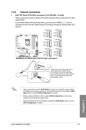
... cables. If you can create a RAID 0, 1, 5, and 10 configuration with the Intel® Rapid Storage Technology through the onboard Intel® Z97 chipset. 1.2.9 Internal connectors 1. ASUS MAXIMUS VII GENE 1-39 Intel® Z97 Serial ATA 6 Gb/s connectors (7-pin SATA6G_1-6 [red]) These connectors connect to section SATA Configuration for details. • Before creating a RAID set...
... cables. If you can create a RAID 0, 1, 5, and 10 configuration with the Intel® Rapid Storage Technology through the onboard Intel® Z97 chipset. 1.2.9 Internal connectors 1. ASUS MAXIMUS VII GENE 1-39 Intel® Z97 Serial ATA 6 Gb/s connectors (7-pin SATA6G_1-6 [red]) These connectors connect to section SATA Configuration for details. • Before creating a RAID set...

User Guide
Page 55
... cable to the ASUS Q-Connector (USB) first, and then install the Q-Connector (USB) to any of the system chassis. 3. Connect the USB module cable to the USB connector onboard if your chassis supports front panel USB ports. USB 2.0 connectors (10-1 pin USB13, USB1112) These connectors are for USB 2.0 ports. Chapter 1 ASUS MAXIMUS VII GENE 1-41
... cable to the ASUS Q-Connector (USB) first, and then install the Q-Connector (USB) to any of the system chassis. 3. Connect the USB module cable to the USB connector onboard if your chassis supports front panel USB ports. USB 2.0 connectors (10-1 pin USB13, USB1112) These connectors are for USB 2.0 ports. Chapter 1 ASUS MAXIMUS VII GENE 1-41


