
User Manual
Page 13
Before you for the following items. Motherboard Cables Accessories Application DVD Documentations ASUS M5A87 motherboard 2 x Serial ATA 6.0Gb/s cables 1 x I/O shield ASUS motherboard Support DVD User Manual If any of ASUS quality motherboards! The motherboard delivers a host of new features and latest technologies...; Socket AM3+ multi-core processors with unique L3 cache and delivers better overclocking capabilities with less power consumption. ASUS M5A87 1-1 Thank you start installing the motherboard, and hardware devices on it another standout in your package with the list...
Before you for the following items. Motherboard Cables Accessories Application DVD Documentations ASUS M5A87 motherboard 2 x Serial ATA 6.0Gb/s cables 1 x I/O shield ASUS motherboard Support DVD User Manual If any of ASUS quality motherboards! The motherboard delivers a host of new features and latest technologies...; Socket AM3+ multi-core processors with unique L3 cache and delivers better overclocking capabilities with less power consumption. ASUS M5A87 1-1 Thank you start installing the motherboard, and hardware devices on it another standout in your package with the list...
User Manual
Page 15
... design protects expensive devices and the motherboard from switching power supply unit (PSU). MemOK! MemOK! ASUS M5A87 1-3 guickly ensures memory boot compatibility. This all the exclusive ASUS features into an overclocking button. and its fast user-friendly interface, ASUS AI Suite II consolidates all -in-one simple to supervise overclocking, energy management, fan speed...
... design protects expensive devices and the motherboard from switching power supply unit (PSU). MemOK! MemOK! ASUS M5A87 1-3 guickly ensures memory boot compatibility. This all the exclusive ASUS features into an overclocking button. and its fast user-friendly interface, ASUS AI Suite II consolidates all -in-one simple to supervise overclocking, energy management, fan speed...
User Manual
Page 17
ASUS M5A87 1-5 Failure to do so may cause severe damage to avoid touching the ICs on them. • Whenever you uninstall any component, place it on a grounded ...
ASUS M5A87 1-5 Failure to do so may cause severe damage to avoid touching the ICs on them. • Whenever you uninstall any component, place it on a grounded ...
User Manual
Page 19
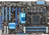
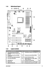
... CPU and chassis fan connectors (3-pin PWR_FAN, 4-pin CPU_FAN and 3-pin CHA_FAN) 2. Front panel audio connector (10-1 pin AAFP) 1-25 ASUS M5A87 1-7 Core Unlocker switch (CORE_UNLOCKER) 4. COM1 LPT 1.5.3 Motherboard layout 1 2 34 1 1 21.3cm(8.4in) KB_USB56 CORE_UNLOCKER 02LED1 PWR_FAN ATX12V ...AM3+ USB3_12 LAN1_USB12 30.5cm(12.0in) CHA_FAN AUDIO AAFP asmedia ASM1042 Realtek RTL8111E PCIEX1_1 ICS 9LPRS483 AMD® 870 M5A87 PCIEX16 PCIEX1_2 Super I/O PCI1 PCI2 2 EATXPWR AMD® SB850 Lithium Cell CMOS Power 16Mb BIOS SATA6G_1 SATA6G_3 SATA6G_5 SATA6G_2 ...
... CPU and chassis fan connectors (3-pin PWR_FAN, 4-pin CPU_FAN and 3-pin CHA_FAN) 2. Front panel audio connector (10-1 pin AAFP) 1-25 ASUS M5A87 1-7 Core Unlocker switch (CORE_UNLOCKER) 4. COM1 LPT 1.5.3 Motherboard layout 1 2 34 1 1 21.3cm(8.4in) KB_USB56 CORE_UNLOCKER 02LED1 PWR_FAN ATX12V ...AM3+ USB3_12 LAN1_USB12 30.5cm(12.0in) CHA_FAN AUDIO AAFP asmedia ASM1042 Realtek RTL8111E PCIEX1_1 ICS 9LPRS483 AMD® 870 M5A87 PCIEX16 PCIEX1_2 Super I/O PCI1 PCI2 2 EATXPWR AMD® SB850 Lithium Cell CMOS Power 16Mb BIOS SATA6G_1 SATA6G_3 SATA6G_5 SATA6G_2 ...

User Manual
Page 21
CPU FAN PWM CPU FAN IN CPU FAN PWR GND ASUS M5A87 1-9 You can occur if you fail to plug this connector. When the CPU is locked. 6. CPU_FAN M5A87 M5A87 CPU fan connector DO NOT forget to indicate that comes with the heatsink package. Hardware monitoring errors can also refer to secure the CPU. Install...
CPU FAN PWM CPU FAN IN CPU FAN PWR GND ASUS M5A87 1-9 You can occur if you fail to plug this connector. When the CPU is locked. 6. CPU_FAN M5A87 M5A87 CPU fan connector DO NOT forget to indicate that comes with the heatsink package. Hardware monitoring errors can also refer to secure the CPU. Install...
User Manual
Page 23
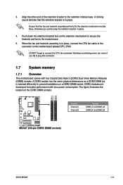
.... Align the other end of the DDR3 DIMM sockets: DIMM_A1 DIMM_A2 DIMM_B1 DIMM_B2 Channel Channel A Channel B Sockets DIMM_A1 and DIMM_A2 DIMM_B1 and DIMM_B2 M5A87 M5A87 240-pin DDR3 DIMM sockets ASUS M5A87 1-11 Push down the retention bracket lock on the motherboard labeled CPU_FAN. A DDR3 module has the same physical dimensions as a DDR2 DIMM...
.... Align the other end of the DDR3 DIMM sockets: DIMM_A1 DIMM_A2 DIMM_B1 DIMM_B2 Channel Channel A Channel B Sockets DIMM_A1 and DIMM_A2 DIMM_B1 and DIMM_B2 M5A87 M5A87 240-pin DDR3 DIMM sockets ASUS M5A87 1-11 Push down the retention bracket lock on the motherboard labeled CPU_FAN. A DDR3 module has the same physical dimensions as a DDR2 DIMM...

User Manual
Page 29
1.7.3 Installing a DIMM Unplug the power supply before adding or removing DIMMs or other system components. DIMM notch ASUS M5A87 1-17 Locked Retaining Clip 1.7.4 Removing a DIMM To remove a DIMM: 1. Firmly insert the DIMM into a socket in the wrong direction to both the motherboard and the ...
1.7.3 Installing a DIMM Unplug the power supply before adding or removing DIMMs or other system components. DIMM notch ASUS M5A87 1-17 Locked Retaining Clip 1.7.4 Removing a DIMM To remove a DIMM: 1. Firmly insert the DIMM into a socket in the wrong direction to both the motherboard and the ...
User Manual
Page 31
... about 5~10 seconds, then move the jumper again to pins 2-3. Shut down the key during the boot process and enter BIOS setup to default values. ASUS M5A87 1-19 Hold down and reboot the system so the BIOS can clear the CMOS memory of date, time, and system setup parameters by erasing the... CMOS RTC RAM data. For system failure due to overclocking. M5A87 M5A87 Clear RTC RAM CLRTC 12 23 Normal (Default) Clear RTC To erase the RTC RAM: 1. Plug the power cord and turn ON the computer. 4. After...
... about 5~10 seconds, then move the jumper again to pins 2-3. Shut down the key during the boot process and enter BIOS setup to default values. ASUS M5A87 1-19 Hold down and reboot the system so the BIOS can clear the CMOS memory of date, time, and system setup parameters by erasing the... CMOS RTC RAM data. For system failure due to overclocking. M5A87 M5A87 Clear RTC RAM CLRTC 12 23 Normal (Default) Clear RTC To erase the RTC RAM: 1. Plug the power cord and turn ON the computer. 4. After...
User Manual
Page 33
... GND CPU FAN PWM CPU FAN IN CPU FAN PWR GND CHA_FAN M5A87 GND +12V Rotation M5A87 Fan connectors DO NOT forget to connect the fan cables to support 8-channel audio output. 7. USB 3.0 ports 1 and 2. ASUS M5A87 1-21 DO NOT place jumper caps on the motherboard, ensuring that the... black wire of each cable matches the ground pin of the connector. Insufficient air flow inside the system may damage the motherboard components. Only the 4-pin CPU fan supports the ASUS Q-Fan feature. These...
... GND CPU FAN PWM CPU FAN IN CPU FAN PWR GND CHA_FAN M5A87 GND +12V Rotation M5A87 Fan connectors DO NOT forget to connect the fan cables to support 8-channel audio output. 7. USB 3.0 ports 1 and 2. ASUS M5A87 1-21 DO NOT place jumper caps on the motherboard, ensuring that the... black wire of each cable matches the ground pin of the connector. Insufficient air flow inside the system may damage the motherboard components. Only the 4-pin CPU fan supports the ASUS Q-Fan feature. These...

User Manual
Page 35
...Pack 3 or later version before using hot-plug and NCQ, set the type of the SATA connectors in the BIOS to IDE mode by default. ASUS M5A87 1-23 In IDE mode, you intend to create a Serial ATA RAID set using these connectors, set to [AHCI]. If you can create a ...(7-pin SATA6G 1~6) These connectors are set the type of the SATA connectors in the BIOS to these connectors. SATA6G_1 SATA6G_3 SATA6G_5 SATA6G_2 SATA6G_4 SATA6G_6 M5A87 M5A87 SATA 6.0Gb/s connectors • These connectors are for the Serial ATA 6.0 Gb/s signal cables for details. The Serial ATA RAID feature is...
...Pack 3 or later version before using hot-plug and NCQ, set the type of the SATA connectors in the BIOS to IDE mode by default. ASUS M5A87 1-23 In IDE mode, you intend to create a Serial ATA RAID set using these connectors, set to [AHCI]. If you can create a ...(7-pin SATA6G 1~6) These connectors are set the type of the SATA connectors in the BIOS to these connectors. SATA6G_1 SATA6G_3 SATA6G_5 SATA6G_2 SATA6G_4 SATA6G_6 M5A87 M5A87 SATA 6.0Gb/s connectors • These connectors are for the Serial ATA 6.0 Gb/s signal cables for details. The Serial ATA RAID feature is...

User Manual
Page 37
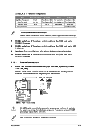
.... See section 2.5.3 Onboard Devices Configuration for an additional Sony/Philips Digital Interface (S/PDIF) port. +5V SPDIFOUT GND M5A87 SPDIF_OUT M5A87 Digital audio connector Ensure that supports either High Definition Audio or AC`97 audio standard. Front panel audio connector (10...-1 pin AAFP) This connector is for a chassis-mounted front panel audio I /O module is purchased separately. 6. ASUS M5A87 1-25 The S/PDIF module is purchased separately. Digital audio connector (4-1 pin SPDIF_OUT) This connector is for details. • The front panel...
.... See section 2.5.3 Onboard Devices Configuration for an additional Sony/Philips Digital Interface (S/PDIF) port. +5V SPDIFOUT GND M5A87 SPDIF_OUT M5A87 Digital audio connector Ensure that supports either High Definition Audio or AC`97 audio standard. Front panel audio connector (10...-1 pin AAFP) This connector is for a chassis-mounted front panel audio I /O module is purchased separately. 6. ASUS M5A87 1-25 The S/PDIF module is purchased separately. Digital audio connector (4-1 pin SPDIF_OUT) This connector is for details. • The front panel...
User Manual
Page 39
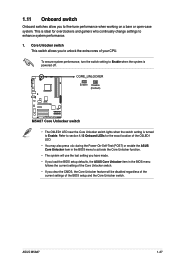
ASUS M5A87 1-27 To ensure system performance, turn the switch setting to Enable when the system is ...• The system will use the last setting you have made. • If you load the BIOS setup defaults, the ASUS Core Unlocker item in the BIOS menu to enhance system performance. 1. This is ideal for the exact location of the O2LED1 ...11 Onboard switch Onboard switches allow you to unlock the extra cores of the BIOS setup and the Core Unlocker switch. M5A87 M5A87 Core Unlocker switch • The O2LED1 LED near the Core Unlocker switch lights when the switch setting is powered off...
ASUS M5A87 1-27 To ensure system performance, turn the switch setting to Enable when the system is ...• The system will use the last setting you have made. • If you load the BIOS setup defaults, the ASUS Core Unlocker item in the BIOS menu to enhance system performance. 1. This is ideal for the exact location of the O2LED1 ...11 Onboard switch Onboard switches allow you to unlock the extra cores of the BIOS setup and the Core Unlocker switch. M5A87 M5A87 Core Unlocker switch • The O2LED1 LED near the Core Unlocker switch lights when the switch setting is powered off...
User Manual
Page 41
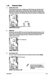
... will continue lighting until the problem is set to locate the root problem within a second. DRAM LED M5A87 M5A87 DRAM LED 3. O2LED1 M5A87 M5A87 Core Unlocker LED ASUS M5A87 The Core Unlocker LED keeps on lighting even though the ASUS Core Unlocker item in any motherboard component. The illustration below shows the location of the onboard LED...
... will continue lighting until the problem is set to locate the root problem within a second. DRAM LED M5A87 M5A87 DRAM LED 3. O2LED1 M5A87 M5A87 Core Unlocker LED ASUS M5A87 The Core Unlocker LED keeps on lighting even though the ASUS Core Unlocker item in any motherboard component. The illustration below shows the location of the onboard LED...

User Manual
Page 43
... list, select either through a network or an Internet Service Provider (ISP). • This utility is available in the optical drive. The ASUS Update main screen appears. Chapter 2 BIOS information 2.1 Managing and updating your BIOS Save a copy of the following methods: Updating from the ...BIOS version that comes with the motherboard package. Click Update button from the Quick Bar, and then click ASUS Update from the Internet, then click Next. Installing ASUS Update To install ASUS Update: 1. ASUS M5A87 2-1 Follow the onscreen instructions to launch the AI Suite II utility.
... list, select either through a network or an Internet Service Provider (ISP). • This utility is available in the optical drive. The ASUS Update main screen appears. Chapter 2 BIOS information 2.1 Managing and updating your BIOS Save a copy of the following methods: Updating from the ...BIOS version that comes with the motherboard package. Click Update button from the Quick Bar, and then click ASUS Update from the Internet, then click Next. Installing ASUS Update To install ASUS Update: 1. ASUS M5A87 2-1 Follow the onscreen instructions to launch the AI Suite II utility.

User Manual
Page 45
... BIOS file. • Before using this utility, rename the BIOS file in the USB flash drive into M5A87.ROM. • Download the latest BIOS file from the ASUS website at www.asus.com. • This function supports USB flash disks with FAT 32/16 format and single partition only. ... the system while updating the BIOS to prevent system boot failure! 2.1.3 ASUS CrashFree BIOS 3 ASUS CrashFree BIOS 3 is an auto recovery tool that contains the BIOS file to the USB port or to ensure system compatibility and stability. ASUS M5A87 2-3 Recovering the BIOS To recover the BIOS: 1. You can cause...
... BIOS file. • Before using this utility, rename the BIOS file in the USB flash drive into M5A87.ROM. • Download the latest BIOS file from the ASUS website at www.asus.com. • This function supports USB flash disks with FAT 32/16 format and single partition only. ... the system while updating the BIOS to prevent system boot failure! 2.1.3 ASUS CrashFree BIOS 3 ASUS CrashFree BIOS 3 is an auto recovery tool that contains the BIOS file to the USB port or to ensure system compatibility and stability. ASUS M5A87 2-3 Recovering the BIOS To recover the BIOS: 1. You can cause...

User Manual
Page 47
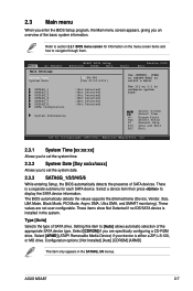
2.2.1 BIOS menu screen Menu items Menu bar Configuration fields Main Ai Tweaker M5A87 BIOS Setup Advanced Power Boot Main Settings System Time [16:34:30] System Date [Tue 01/11/2011] SATA6G_1 SATA6G_2 SATA6G_3 SATA6G_4 SATA6G_5 SATA6G_6 SATA ... corner of the navigation keys differ from one screen to select items in the menu and change the settings. Use the navigation keys to another. ASUS M5A87 2-5
2.2.1 BIOS menu screen Menu items Menu bar Configuration fields Main Ai Tweaker M5A87 BIOS Setup Advanced Power Boot Main Settings System Time [16:34:30] System Date [Tue 01/11/2011] SATA6G_1 SATA6G_2 SATA6G_3 SATA6G_4 SATA6G_5 SATA6G_6 SATA ... corner of the navigation keys differ from one screen to select items in the menu and change the settings. Use the navigation keys to another. ASUS M5A87 2-5
User Manual
Page 49
...ARMD] This item only appears in the system. Refer to section 2.2.1 BIOS menu screen for each SATA device. Main Ai Tweaker Main Settings M5A87 BIOS Setup Advanced Power Boot System Time [16:34:30] System Date [Tue 01/11/2011] SATA6G_1 SATA6G_2 SATA6G_3 SATA6G_4 SATA6G_5 SATA6G_6 SATA ... Mode, PIO Mode, Async DMA, Ultra DMA, and SMART monitoring). Select [CDROM] if you to [Auto] allows automatic selection of SATA drive. ASUS M5A87 2-7 Setting this item to set the system time. 2.3.2 System Date [Day xx/xx/xxxx] Allows you are not user-configurable. Select [ARMD] ...
...ARMD] This item only appears in the system. Refer to section 2.2.1 BIOS menu screen for each SATA device. Main Ai Tweaker Main Settings M5A87 BIOS Setup Advanced Power Boot System Time [16:34:30] System Date [Tue 01/11/2011] SATA6G_1 SATA6G_2 SATA6G_3 SATA6G_4 SATA6G_5 SATA6G_6 SATA ... Mode, PIO Mode, Async DMA, Ultra DMA, and SMART monitoring). Select [CDROM] if you to [Auto] allows automatic selection of SATA drive. ASUS M5A87 2-7 Setting this item to set the system time. 2.3.2 System Date [Day xx/xx/xxxx] Allows you are not user-configurable. Select [ARMD] ...
User Manual
Page 51
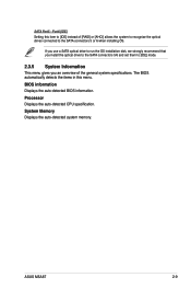
ASUS M5A87 2-9 BIOS information Displays the auto-detected BIOS information. Processor Displays the auto-detected CPU specification. System Memory Displays the auto-detected system memory. SATA Port5 - ...
ASUS M5A87 2-9 BIOS information Displays the auto-detected BIOS information. Processor Displays the auto-detected CPU specification. System Memory Displays the auto-detected system memory. SATA Port5 - ...
User Manual
Page 53
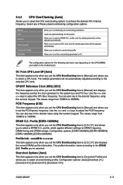
... the CPU OverClocking item to [Manual] and allows you to DRAM frequency, DRAM timing and DRAM voltage. Configuration options: [Auto] [Overclock 2%] [Overclock 5%] [Overclock 8%] [Overclock 10%] ASUS M5A87 2-11 profile, and the related parameters will be automatically adjusted according to [D.O.C.P.] and displays the current DRAM profile information. Use the and keys to select...
... the CPU OverClocking item to [Manual] and allows you to DRAM frequency, DRAM timing and DRAM voltage. Configuration options: [Auto] [Overclock 2%] [Overclock 5%] [Overclock 8%] [Overclock 10%] ASUS M5A87 2-11 profile, and the related parameters will be automatically adjusted according to [D.O.C.P.] and displays the current DRAM profile information. Use the and keys to select...
User Manual
Page 55
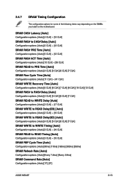
...] [90ns] [110ns] [160ns] [300ns] [350ns] DRAM Refresh Rate [Auto] Configuration options: [Auto] [Every 7.8ms] [Every 3.9ms] DRAM Command Rate [Auto] Configuration options: [Auto] [1T] [2T] ASUS M5A87 2-13 2.4.7 DRAM Timing Configuration The configuration options for some of the following items vary depending on the DIMMs you install on the motherboard.
...] [90ns] [110ns] [160ns] [300ns] [350ns] DRAM Refresh Rate [Auto] Configuration options: [Auto] [Every 7.8ms] [Every 3.9ms] DRAM Command Rate [Auto] Configuration options: [Auto] [1T] [2T] ASUS M5A87 2-13 2.4.7 DRAM Timing Configuration The configuration options for some of the following items vary depending on the DIMMs you install on the motherboard.


