User Manual
Page 25
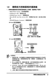
PWR Ground Reset Ground 10-1 pin IDE_LED RESET PWRSW * Requires an ATX power supply. 紅色 1 表示 PIN1 的位置 PLED+ PLEDPWR GND IDELED+ IDELED- SPEAKER、RESET 與 PWRSW IDE_LED 與 PLED PIN1 PIN1 4 ...
PWR Ground Reset Ground 10-1 pin IDE_LED RESET PWRSW * Requires an ATX power supply. 紅色 1 表示 PIN1 的位置 PLED+ PLEDPWR GND IDELED+ IDELED- SPEAKER、RESET 與 PWRSW IDE_LED 與 PLED PIN1 PIN1 4 ...
User Manual
Page 26
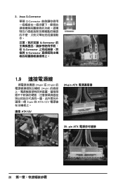
pin ATX 26 2. Asus Q-Connector 華碩 Q-Connector Q-Connector Q-Connector Q-Connector 1.9 24-pin 或 20-pin 24-pin 4-pin 的 ATX+12V 連接 ATX12V 24-pin ATX 20-
pin ATX 26 2. Asus Q-Connector 華碩 Q-Connector Q-Connector Q-Connector Q-Connector 1.9 24-pin 或 20-pin 24-pin 4-pin 的 ATX+12V 連接 ATX12V 24-pin ATX 20-
User Manual
Page 13
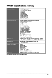
M4A78T-E specifications summary Back panel I/O ports Internal I/O connectors BIOS features Manageability Support DVD contents Form factor 1 x PS/2 keyboard port 1 x S/PDIF Out port (Optical) 1 x HDMI port 1 x DVI ... Out Header Front panel audio connector Chassis Intrusion connector CD audio in 24-pin ATX Power connector System Panel (Q-Connector) 4-pin ATX 12V Power connector 8 Mb Flash ROM, AMI BIOS, PnP, DMI 2.0, WfM 2.0, SM BIOS 2.3, ACPI 2.0a, ASUS EZ Flash 2, ASUS CrashFree BIOS 3 WOL by PME, WOR by PME, WOR by Ring, PXE, Chassis...
M4A78T-E specifications summary Back panel I/O ports Internal I/O connectors BIOS features Manageability Support DVD contents Form factor 1 x PS/2 keyboard port 1 x S/PDIF Out port (Optical) 1 x HDMI port 1 x DVI ... Out Header Front panel audio connector Chassis Intrusion connector CD audio in 24-pin ATX Power connector System Panel (Q-Connector) 4-pin ATX 12V Power connector 8 Mb Flash ROM, AMI BIOS, PnP, DMI 2.0, WfM 2.0, SM BIOS 2.3, ACPI 2.0a, ASUS EZ Flash 2, ASUS CrashFree BIOS 3 WOL by PME, WOR by PME, WOR by Ring, PXE, Chassis...
User Manual
Page 21
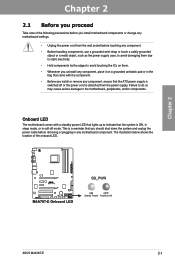
...in any component, ensure that the ATX power supply is switched off or the power cord is a reminder that the system is ON, in sleep mode, or in the bag that came with the component. • Before you install or remove any motherboard component. The illustration below shows the...8226; Unplug the power cord from the power supply. Chapter 2 2.1 Before you proceed Take note of the onboard LED. Chapter 2 ASUS M4A78T-E 2-1 Onboard LED The motherboard comes with a standby power LED that lights up to indicate that you should shut down the system and unplug the power cable before ...
...in any component, ensure that the ATX power supply is switched off or the power cord is a reminder that the system is ON, in sleep mode, or in the bag that came with the component. • Before you install or remove any motherboard component. The illustration below shows the...8226; Unplug the power cord from the power supply. Chapter 2 2.1 Before you proceed Take note of the onboard LED. Chapter 2 ASUS M4A78T-E 2-1 Onboard LED The motherboard comes with a standby power LED that lights up to indicate that you should shut down the system and unplug the power cable before ...
User Manual
Page 23
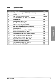
...33 2-5 2-9, 2-31 2-10 2-27 2-19 2-20 2-28 2-1 2-32 2-35 2-29 2-30 2-26 2-26 2-29 2-34 2-30 Chapter 2 ASUS M4A78T-E 2-3 CPU overvoltage setting (3-pin OV_CPU) 8. Optical drive audio connector (4-pin CD) 17. Digital audio connector (4-1 pin SPDIF_OUT) 16. IEEE 1394a port... pin FLOPPY) 15. DDR3 DIMM slots 5. Front panel audio connector (10-1 pin AAFP) 18. IDE connector (40-1 pin PRI_IDE) 6. ATX power connectors (24-pin EATXPWR, 4-pin ATX12V) 2. 2.2.2 Layout contents Connectors/Jumpers/Slots 1. CPU, chassis, and power fan connectors (4-pin CPU_FAN...
...33 2-5 2-9, 2-31 2-10 2-27 2-19 2-20 2-28 2-1 2-32 2-35 2-29 2-30 2-26 2-26 2-29 2-34 2-30 Chapter 2 ASUS M4A78T-E 2-3 CPU overvoltage setting (3-pin OV_CPU) 8. Optical drive audio connector (4-pin CD) 17. Digital audio connector (4-1 pin SPDIF_OUT) 16. IEEE 1394a port... pin FLOPPY) 15. DDR3 DIMM slots 5. Front panel audio connector (10-1 pin AAFP) 18. IDE connector (40-1 pin PRI_IDE) 6. ATX power connectors (24-pin EATXPWR, 4-pin ATX12V) 2. 2.2.2 Layout contents Connectors/Jumpers/Slots 1. CPU, chassis, and power fan connectors (4-pin CPU_FAN...

User Manual
Page 53
... a higher power output is inadequate. • If you use a power supply unit (PSU) that complies with ATX 12 V Specification 2.0 (or later version) and provides a minimum power of a PSU with more power-consuming devices. Chapter 2 11. ASUS M4A78T-E 2-33 Find the proper orientation and push down firmly until the connectors completely fit. • For...
... a higher power output is inadequate. • If you use a power supply unit (PSU) that complies with ATX 12 V Specification 2.0 (or later version) and provides a minimum power of a PSU with more power-consuming devices. Chapter 2 11. ASUS M4A78T-E 2-33 Find the proper orientation and push down firmly until the connectors completely fit. • For...

User Manual
Page 55
... power, and blinks when the system is in sleep or soft-off the system power. The IDE LED lights up when you to this connector. ASUS M4A78T-E 2-35 Pressing the power switch for more than four seconds while the system is ON turns the system OFF. • Reset button (2-pin RESET...) This 2-pin connector is for the system power LED. Connect the chassis power LED cable to hear system beeps and warnings. • ATX power button/soft-off button (2-pin PWRSW) This connector is for the chassis-mounted reset button for the HDD Activity LED. Chapter 2 • System...
... power, and blinks when the system is in sleep or soft-off the system power. The IDE LED lights up when you to this connector. ASUS M4A78T-E 2-35 Pressing the power switch for more than four seconds while the system is ON turns the system OFF. • Reset button (2-pin RESET...) This 2-pin connector is for the system power LED. Connect the chassis power LED cable to hear system beeps and warnings. • ATX power button/soft-off button (2-pin PWRSW) This connector is for the chassis-mounted reset button for the HDD Activity LED. Chapter 2 • System...

User Manual
Page 57
... replace the system case cover. 2. After making all switches are running, the BIOS beeps (see anything within 30 seconds from the time you press the ATX power button. Monitor b. For systems with "green" standards or if it has a "power standby" feature, the monitor LED may have failed a power... While the system is equipped with the last device on the screen. While the tests are off mode regardless of the system chassis. 4. ASUS M4A78T-E 2-37 The system then runs the power-on , hold down the key to disabled No keyboard detected No memory detected No VGA detected ...
... replace the system case cover. 2. After making all switches are running, the BIOS beeps (see anything within 30 seconds from the time you press the ATX power button. Monitor b. For systems with "green" standards or if it has a "power standby" feature, the monitor LED may have failed a power... While the system is equipped with the last device on the screen. While the tests are off mode regardless of the system chassis. 4. ASUS M4A78T-E 2-37 The system then runs the power-on , hold down the key to disabled No keyboard detected No memory detected No VGA detected ...

User Manual
Page 84
This feature requires an ATX power supply that provides at least 1A on the system through a PCI/PCIE/onboard LAN device. Turning an external modem off and then back on ... in Soft-off or on state, whatever the system state was before the AC power loss. Chapter 3 3-26 Chapter 3: BIOS setup This feature requires an ATX power supply that turns the system power on the +5VSB lead. Power On By RTC Alarm [Disabled] [Disabled] Disables RTC to generate a wake event. [Enabled...
This feature requires an ATX power supply that provides at least 1A on the system through a PCI/PCIE/onboard LAN device. Turning an external modem off and then back on ... in Soft-off or on state, whatever the system state was before the AC power loss. Chapter 3 3-26 Chapter 3: BIOS setup This feature requires an ATX power supply that turns the system power on the +5VSB lead. Power On By RTC Alarm [Disabled] [Disabled] Disables RTC to generate a wake event. [Enabled...

