
User Manual
Page 1
Motherboard
Motherboard

User Manual
Page 1
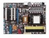
M4A78 PLUS Motherboard
M4A78 PLUS Motherboard
User Manual
Page 3
Contents Notices...vi Safety information vii About this guide vii M4A78 PLUS specifications summary ix Chapter 1 Product introduction 1.1 Welcome 1-1 1.2 Package contents 1-1 1.3 Special features 1-1 1.3.1 Product highlights 1-1 1.3.2 Innovative ASUS features 1-4 1.4 Before you proceed 1-6 Onboard LED 1-6 1.5 Motherboard overview 1-7 1.5.1 Placement direction 1-7 1.5.2 Screw holes 1-7 1.5.3 Motherboard layout 1-8 1.5.4 Layout contents 1-8 1.6 Central Processing Unit (CPU 1-9 1.6.1 Installing the CPU 1-9 1.6.2 Installing the heatsink and fan 1-11...
Contents Notices...vi Safety information vii About this guide vii M4A78 PLUS specifications summary ix Chapter 1 Product introduction 1.1 Welcome 1-1 1.2 Package contents 1-1 1.3 Special features 1-1 1.3.1 Product highlights 1-1 1.3.2 Innovative ASUS features 1-4 1.4 Before you proceed 1-6 Onboard LED 1-6 1.5 Motherboard overview 1-7 1.5.1 Placement direction 1-7 1.5.2 Screw holes 1-7 1.5.3 Motherboard layout 1-8 1.5.4 Layout contents 1-8 1.6 Central Processing Unit (CPU 1-9 1.6.1 Installing the CPU 1-9 1.6.2 Installing the heatsink and fan 1-11...
User Manual
Page 6
... digital apparatus does not exceed the Class B limits for radio noise emissions from that may cause harmful interference to radio communications. DO NOT throw the motherboard in the Radio Interference Regulations of the Canadian Department of Communications. This symbol of the crossed out wheeled bin indicates that interference will not occur...
... digital apparatus does not exceed the Class B limits for radio noise emissions from that may cause harmful interference to radio communications. DO NOT throw the motherboard in the Radio Interference Regulations of the Canadian Department of Communications. This symbol of the crossed out wheeled bin indicates that interference will not occur...

User Manual
Page 7
... and staples away from connectors, slots, sockets and circuitry. • Avoid dust, humidity, and temperature extremes. Detailed descriptions of the motherboard and the new technology it supports. • Chapter 2: BIOS information This chapter tells how to fix it , carefully read all the...power supply is set to the correct voltage in any damage, contact your retailer. If you need when installing and configuring the motherboard. Safety information Electrical safety • To prevent electrical shock hazard, disconnect the power cable from the electrical outlet before relocating the...
... and staples away from connectors, slots, sockets and circuitry. • Avoid dust, humidity, and temperature extremes. Detailed descriptions of the motherboard and the new technology it supports. • Chapter 2: BIOS information This chapter tells how to fix it , carefully read all the...power supply is set to the correct voltage in any damage, contact your retailer. If you need when installing and configuring the motherboard. Safety information Electrical safety • To prevent electrical shock hazard, disconnect the power cable from the electrical outlet before relocating the...

User Manual
Page 11
... with unique L3 cache and delivers better overclocking capabilities with the list below. 1.2 Package contents Check your motherboard package for buying an ASUS® M4A78 PLUS motherboard! Chapter 1: Product introduction 1-1 Before you for the following items. Motherboard Cables Accessories Application DVD Documentations ASUS M4A78 PLUS motherboard 2 x Serial ATA cables 1 x 2in1 SATA power cable 1 x Ultra DMA 133/100/66 cable 1 x I/O shield...
... with unique L3 cache and delivers better overclocking capabilities with the list below. 1.2 Package contents Check your motherboard package for buying an ASUS® M4A78 PLUS motherboard! Chapter 1: Product introduction 1-1 Before you for the following items. Motherboard Cables Accessories Application DVD Documentations ASUS M4A78 PLUS motherboard 2 x Serial ATA cables 1 x 2in1 SATA power cable 1 x Ultra DMA 133/100/66 cable 1 x I/O shield...

User Manual
Page 12
...increase memory data transfer rate and computing efficiency, enhancing system performance in 3D graphics and other memory demanding applications. 1-2 ASUS M4A78 PLUS Adjust your display configurations, experiment with your advanced 3D settings, and check the effect with rendering speed, eliminating the...Center to 5200MT/s via HyperTransport™ 3.0 based system bus, and AMD® Cool 'n' Quiet™ Technology. This motherboard provides excellent compatibility and flexibility by supporting either 64-bit or 32-bit architecture. CrossFire ignites with the higher antialiasing, ...
...increase memory data transfer rate and computing efficiency, enhancing system performance in 3D graphics and other memory demanding applications. 1-2 ASUS M4A78 PLUS Adjust your display configurations, experiment with your advanced 3D settings, and check the effect with rendering speed, eliminating the...Center to 5200MT/s via HyperTransport™ 3.0 based system bus, and AMD® Cool 'n' Quiet™ Technology. This motherboard provides excellent compatibility and flexibility by supporting either 64-bit or 32-bit architecture. CrossFire ignites with the higher antialiasing, ...
User Manual
Page 13
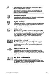
...double speed and bandwidth which enhances system performance. Refer to the ASUS website at www.asus.com for the supported CPU models. • Due to 40 times faster at the back I /O port This motherboard provides convenient connectivity to provide efficient power management for advanced operating ...systems. SATA on the Go This motherboard supports hard drives based on the Serial ...
...double speed and bandwidth which enhances system performance. Refer to the ASUS website at www.asus.com for the supported CPU models. • Due to 40 times faster at the back I /O port This motherboard provides convenient connectivity to provide efficient power management for advanced operating ...systems. SATA on the Go This motherboard supports hard drives based on the Serial ...

User Manual
Page 14
... power usage to ensure quiet, cool, and efficient operation. 1-4 ASUS M4A78 PLUS Turbo Key ASUS Turbo Key allows you to turn the PC power button into 256-color boot logos to personalize your system. ASUS MyLogo2™ Turn your favorite photos into an overclocking button. After...work or games, simply through pressing the button. ASUS CrashFree BIOS 3 ASUS CrashFree BIOS 3 is built into the motherboard, so you to restore a corrupted BIOS file using an OS-based utility. 1.3.2 Innovative ASUS features ASUS EPU The ASUS EPU (Energy Processing Unit) provides total system power...
... power usage to ensure quiet, cool, and efficient operation. 1-4 ASUS M4A78 PLUS Turbo Key ASUS Turbo Key allows you to turn the PC power button into 256-color boot logos to personalize your system. ASUS MyLogo2™ Turn your favorite photos into an overclocking button. After...work or games, simply through pressing the button. ASUS CrashFree BIOS 3 ASUS CrashFree BIOS 3 is built into the motherboard, so you to restore a corrupted BIOS file using an OS-based utility. 1.3.2 Innovative ASUS features ASUS EPU The ASUS EPU (Energy Processing Unit) provides total system power...
User Manual
Page 15
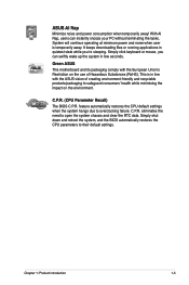
... in line with the European Union's Restriction on the environment. Green ASUS This motherboard and its packaging comply with the ASUS vision of Hazardous Substances (RoHS). feature automatically restores the CPU default settings when the system hangs due to their default settings. ASUS AI Nap Minimize noise and power consumption when temporarily away! C.P.R. (CPU...
... in line with the European Union's Restriction on the environment. Green ASUS This motherboard and its packaging comply with the ASUS vision of Hazardous Substances (RoHS). feature automatically restores the CPU default settings when the system hangs due to their default settings. ASUS AI Nap Minimize noise and power consumption when temporarily away! C.P.R. (CPU...
User Manual
Page 16
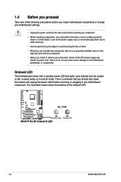
... to indicate that you should shut down the system and unplug the power cable before removing or plugging in soft-off the ATX power supply and detach its power cord. 1.4 Before you proceed Take note of the onboard LED. The illustration below shows ... the power supply case, to avoid damaging them . • Whenever you install or remove any motherboard component. M4A78 PLUS SB_PWR ON OFF Standby Power Powered Off M4A78 PLUS Onboard LED 1-6 ASUS M4A78 PLUS Onboard LED The motherboard comes with the component. • Before you uninstall any component, place it on them due to...
... to indicate that you should shut down the system and unplug the power cable before removing or plugging in soft-off the ATX power supply and detach its power cord. 1.4 Before you proceed Take note of the onboard LED. The illustration below shows ... the power supply case, to avoid damaging them . • Whenever you install or remove any motherboard component. M4A78 PLUS SB_PWR ON OFF Standby Power Powered Off M4A78 PLUS Onboard LED 1-6 ASUS M4A78 PLUS Onboard LED The motherboard comes with the component. • Before you uninstall any component, place it on them due to...
User Manual
Page 17
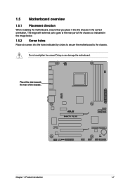
The edge with external ports goes to the chassis. Place this side towards the rear of the chassis as indicated in the correct orientation. M4A78 PLUS Chapter 1: Product introduction 1-7 Doing so can damage the motherboard. Do not overtighten the screws! 1.5 Motherboard overview 1.5.1 Placement direction When installing the motherboard, ensure that you place it into the chassis in the image below. 1.5.2 Screw holes Place six screws into the holes indicated by circles to secure the motherboard to the rear part of the chassis.
The edge with external ports goes to the chassis. Place this side towards the rear of the chassis as indicated in the correct orientation. M4A78 PLUS Chapter 1: Product introduction 1-7 Doing so can damage the motherboard. Do not overtighten the screws! 1.5 Motherboard overview 1.5.1 Placement direction When installing the motherboard, ensure that you place it into the chassis in the image below. 1.5.2 Screw holes Place six screws into the holes indicated by circles to secure the motherboard to the rear part of the chassis.
User Manual
Page 19
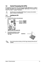
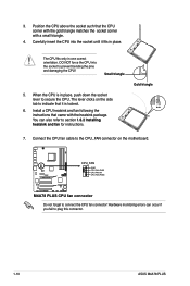
...°-100° angle, otherwise the CPU will not fit in completely. Do not install an Opteron™ processor on the motherboard. Press the lever sideways to unlock the socket, then lift it up to a 90°100° angle. Socket lever...; X2 / processors and AM2+ / AM2 Phenom™ X4 / Phenom™ X3 / Athlon™ X2 / Athlon™ / Sempron™ processors. M4A78 PLUS M4A78 PLUS CPU socket 940 2. Locate the CPU socket on this motherboard. 1.6.1 Installing the CPU To install a CPU: 1. Chapter 1: Product introduction 1-9 1.6 Central Processing Unit (CPU) The...
...°-100° angle, otherwise the CPU will not fit in completely. Do not install an Opteron™ processor on the motherboard. Press the lever sideways to unlock the socket, then lift it up to a 90°100° angle. Socket lever...; X2 / processors and AM2+ / AM2 Phenom™ X4 / Phenom™ X3 / Athlon™ X2 / Athlon™ / Sempron™ processors. M4A78 PLUS M4A78 PLUS CPU socket 940 2. Locate the CPU socket on this motherboard. 1.6.1 Installing the CPU To install a CPU: 1. Chapter 1: Product introduction 1-9 1.6 Central Processing Unit (CPU) The...
User Manual
Page 20
3. When the CPU is locked. 6. Connect the CPU fan cable to connect the CPU fan connector! M4A78 PLUS CPU_FAN GND CPU FAN PWR CPU FAN IN CPU FAN PWM M4A78 PLUS CPU fan connector Do not forget to the CPU_FAN connector on the side tab to indicate that it fits ...occur if you fail to section 1.6.2 Installing heatsink and fan for instructions. The lever clicks on the motherboard. Hardware monitoring errors can also refer to plug this connector. 1-10 ASUS M4A78 PLUS Install a CPU heatsink and fan following the instructions that the CPU corner with the gold triangle matches the...
3. When the CPU is locked. 6. Connect the CPU fan cable to connect the CPU fan connector! M4A78 PLUS CPU_FAN GND CPU FAN PWR CPU FAN IN CPU FAN PWM M4A78 PLUS CPU fan connector Do not forget to the CPU_FAN connector on the side tab to indicate that it fits ...occur if you fail to section 1.6.2 Installing heatsink and fan for instructions. The lever clicks on the motherboard. Hardware monitoring errors can also refer to plug this connector. 1-10 ASUS M4A78 PLUS Install a CPU heatsink and fan following the instructions that the CPU corner with the gold triangle matches the...

User Manual
Page 21
...: 1. If the instructions in this section do not have to remove the retention module base when installing the CPU or installing other motherboard components. • If you purchased a separate CPU heatsink and fan assembly, ensure that you install the heatsink and fan assembly. ...1.6.2 Installing the heatsink and fan Ensure that a Thermal Interface Material is already installed on the motherboard upon purchase. • You do not match the CPU documentation, follow the latter. 2. Place the heatsink on the retention module base....
...: 1. If the instructions in this section do not have to remove the retention module base when installing the CPU or installing other motherboard components. • If you purchased a separate CPU heatsink and fan assembly, ensure that you install the heatsink and fan assembly. ...1.6.2 Installing the heatsink and fan Ensure that a Thermal Interface Material is already installed on the motherboard upon purchase. • You do not match the CPU documentation, follow the latter. 2. Place the heatsink on the retention module base....
User Manual
Page 22
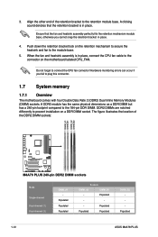
... illustrates the location of the retention bracket to prevent installation on the motherboard labeled CPU_FAN. Populated Populated Populated Sockets DIMM_A2 DIMM_B1 - Populated Populated Populated DIMM_B2 - Populated - - 3. Align the other end of the DDR2 DIMM sockets: DIMM_A1 DIMM_B1 DIMM_A2 DIMM_B2 M4A78 PLUS M4A78 PLUS 240-pin DDR2 DIMM sockets Mode Single-channel Dual-channel (1) Dual-...on a DDR DIMM socket. Do not forget to the 184-pin DDR DIMM. DDR2 DIMMs are notched differently to the retention module base. Populated 1-12 ASUS M4A78 PLUS
... illustrates the location of the retention bracket to prevent installation on the motherboard labeled CPU_FAN. Populated Populated Populated Sockets DIMM_A2 DIMM_B1 - Populated Populated Populated DIMM_B2 - Populated - - 3. Align the other end of the DDR2 DIMM sockets: DIMM_A1 DIMM_B1 DIMM_A2 DIMM_B2 M4A78 PLUS M4A78 PLUS 240-pin DDR2 DIMM sockets Mode Single-channel Dual-channel (1) Dual-...on a DDR DIMM socket. Do not forget to the 184-pin DDR DIMM. DDR2 DIMMs are notched differently to the retention module base. Populated 1-12 ASUS M4A78 PLUS

User Manual
Page 23
...do any of the following: - You may install varying memory sizes in Channel A and Channel B. The motherboard supports up to 16GB memory modules on the motherboard. • This motherboard does not support DIMMs made up of the lower-sized channel for the OS can be about 3GB or... the same vendor. • Due to install 4GB or more memory on the motherboard, the actual usable memory for the dual-channel configuration. The system maps the total size of 256 megabits (Mb) or less. M4A78 PLUS Motherboard Qualified Vendors Lists (QVL) DDR2-667MHz capability Size Vendor Part No.
...do any of the following: - You may install varying memory sizes in Channel A and Channel B. The motherboard supports up to 16GB memory modules on the motherboard. • This motherboard does not support DIMMs made up of the lower-sized channel for the OS can be about 3GB or... the same vendor. • Due to install 4GB or more memory on the motherboard, the actual usable memory for the dual-channel configuration. The system maps the total size of 256 megabits (Mb) or less. M4A78 PLUS Motherboard Qualified Vendors Lists (QVL) DDR2-667MHz capability Size Vendor Part No.
User Manual
Page 28
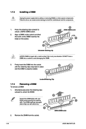
... to unlock the DIMM. 2 Support the DIMM lightly with extra force. 1 DDR2 DIMM notch 2. Remove the DIMM from the socket. 1-18 ASUS M4A78 PLUS Press the retaining clips outward to both the motherboard and the components. 1. Locked Retaining Clip 1.7.4 Removing a DIMM To remove a DIMM: 1. 1.7.3 Installing a DIMM Unplug the power supply before adding or removing...
... to unlock the DIMM. 2 Support the DIMM lightly with extra force. 1 DDR2 DIMM notch 2. Remove the DIMM from the socket. 1-18 ASUS M4A78 PLUS Press the retaining clips outward to both the motherboard and the components. 1. Locked Retaining Clip 1.7.4 Removing a DIMM To remove a DIMM: 1. 1.7.3 Installing a DIMM Unplug the power supply before adding or removing...

User Manual
Page 29
... on the slot. 5. The following sub‑sections describe the slots and the expansion cards that came with the screw you physical injury and damage motherboard components. 1.8.1 Installing an expansion card To install an expansion card: 1. Assign an IRQ to use . 4. See Chapter 2 for the expansion card... as a LAN card, SCSI card, USB card, and other cards that comply with PCI specifications. 1.8.4 PCI Express x1 slot This motherboard supports PCI Express x1 network cards, SCSI cards, and other cards that comply with the PCI Express specifications. 1.8.5 PCI Express x16 slot This...
... on the slot. 5. The following sub‑sections describe the slots and the expansion cards that came with the screw you physical injury and damage motherboard components. 1.8.1 Installing an expansion card To install an expansion card: 1. Assign an IRQ to use . 4. See Chapter 2 for the expansion card... as a LAN card, SCSI card, USB card, and other cards that comply with PCI specifications. 1.8.4 PCI Express x1 slot This motherboard supports PCI Express x1 network cards, SCSI cards, and other cards that comply with the PCI Express specifications. 1.8.5 PCI Express x16 slot This...
User Manual
Page 34
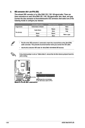
... / 66 signal cable: blue, black, and gray. 2. Connect the blue connector to the motherboard's IDE connector, then select one of device(s) - If any device jumper is for Ultra DMA 133/100/66 IDE devices. M4A78 PLUS IDE connector 1-24 ASUS M4A78 PLUS Master Slave Master Slave Cable connector Black Black Gray Black or gray • Pin...
... / 66 signal cable: blue, black, and gray. 2. Connect the blue connector to the motherboard's IDE connector, then select one of device(s) - If any device jumper is for Ultra DMA 133/100/66 IDE devices. M4A78 PLUS IDE connector 1-24 ASUS M4A78 PLUS Master Slave Master Slave Cable connector Black Black Gray Black or gray • Pin...


