
User Manual
Page 1
M4A78-EM/1394 Motherboard
M4A78-EM/1394 Motherboard

User Manual
Page 3
Contents Notices...vi Safety information...vii About this guide...vii M4A78-EM/1394 specifications summary...ix Chapter 1: 1.1 1.2 1.3 Welcome!...1-1 Package contents...1-1 Special features...1-1 1.3.1 1.3.2 Product highlights...1-1 Innovative ASUS features...1-3 Product introduction 1.4 1.5 Before you proceed...1-5 Motherboard overview...1-6 1.5.1 1.5.2 1.5.3 1.5.4 1.6.1 1.6.2 1.7.1 1.7.2 1.7.3 1.7.4 1.8.1 1.8.2 1.8.3 1.8.4 1.8.5 Placement direction...1-6 Screw holes...1-6 Motherboard layout...1-7 Layout contents...1-7 Installing the CPU...1-8 Installing the heatsink ...
Contents Notices...vi Safety information...vii About this guide...vii M4A78-EM/1394 specifications summary...ix Chapter 1: 1.1 1.2 1.3 Welcome!...1-1 Package contents...1-1 Special features...1-1 1.3.1 1.3.2 Product highlights...1-1 Innovative ASUS features...1-3 Product introduction 1.4 1.5 Before you proceed...1-5 Motherboard overview...1-6 1.5.1 1.5.2 1.5.3 1.5.4 1.6.1 1.6.2 1.7.1 1.7.2 1.7.3 1.7.4 1.8.1 1.8.2 1.8.3 1.8.4 1.8.5 Placement direction...1-6 Screw holes...1-6 Motherboard layout...1-7 Layout contents...1-7 Installing the CPU...1-8 Installing the heatsink ...

User Manual
Page 6
...radiate radio frequency energy and, if not installed and used in municipal waste. REACH Complying with FCC regulations. DO NOT throw the motherboard in a residential installation. These limits are designed to provide reasonable protection against harmful interference in municipal waste. If this equipment. ...Connect the equipment to an outlet on a circuit different from digital apparatus set out in our products at ASUS REACH website at http://green.asus.com/english/REACH.htm. DO NOT throw the mercury-containing button cell battery in municipal waste. This device must...
...radiate radio frequency energy and, if not installed and used in municipal waste. REACH Complying with FCC regulations. DO NOT throw the motherboard in a residential installation. These limits are designed to provide reasonable protection against harmful interference in municipal waste. If this equipment. ...Connect the equipment to an outlet on a circuit different from digital apparatus set out in our products at ASUS REACH website at http://green.asus.com/english/REACH.htm. DO NOT throw the mercury-containing button cell battery in municipal waste. This device must...

User Manual
Page 7
...power supply is organized This guide contains the following parts: • Chapter 1: Product introduction • This chapter describes the features of the motherboard and the new technology it by yourself. If you are not sure about the voltage of the BIOS parameters are not damaged. Before using... , contact your area. To avoid short circuits, keep paper clips, screws, and staples away from the motherboard, ensure that the power cables for the devices are unplugged. Avoid dust, humidity, and temperature extremes. Place the product on it may become...
...power supply is organized This guide contains the following parts: • Chapter 1: Product introduction • This chapter describes the features of the motherboard and the new technology it by yourself. If you are not sure about the voltage of the BIOS parameters are not damaged. Before using... , contact your area. To avoid short circuits, keep paper clips, screws, and staples away from the motherboard, ensure that the power cables for the devices are unplugged. Avoid dust, humidity, and temperature extremes. Place the product on it may become...

User Manual
Page 13
... DVD Documentations If any of ASUS quality motherboards! ASUS M4A78-EM/1394 1-1 It features dual-channel DDR2 1066 memory support and accelerates data transfer rate up to 5200MT/s via HyperTransport™ 3.0based system bus. Chapter 1 1.1 Welcome! This motherboard also supports AMD® CPUs in your package with the list below. 1.2 Package contents ASUS M4A78-EM/1394 motherboard 1 x Serial ATA cable 1 x UltraDMA 133...
... DVD Documentations If any of ASUS quality motherboards! ASUS M4A78-EM/1394 1-1 It features dual-channel DDR2 1066 memory support and accelerates data transfer rate up to 5200MT/s via HyperTransport™ 3.0based system bus. Chapter 1 1.1 Welcome! This motherboard also supports AMD® CPUs in your package with the list below. 1.2 Package contents ASUS M4A78-EM/1394 motherboard 1 x Serial ATA cable 1 x UltraDMA 133...

User Manual
Page 14
... is an AMD chipset designed for both HT1.0 and HT 3.0 interface speed. Dual channel DDR2 1200(O.C.) support To attain top performance, ASUS engineers have successfully unleashed DDR2 1200(O.C.) MHz to meet the higher bandwidth requirements of the latest operating system, 3D graphics, multimedia, and ...174; Phenom™ x4 / Phenom™ x3 / Athlon™ x2 / Athlon™ / Sempron™ processors (socket AM2+/AM2) This motherboard supports AMD® Socket AM2+ multi-core processors. It features dual-channel DDR2 1066 memory support and accelerates data transfer rate up to 5200MT/s via...
... is an AMD chipset designed for both HT1.0 and HT 3.0 interface speed. Dual channel DDR2 1200(O.C.) support To attain top performance, ASUS engineers have successfully unleashed DDR2 1200(O.C.) MHz to meet the higher bandwidth requirements of the latest operating system, 3D graphics, multimedia, and ...174; Phenom™ x4 / Phenom™ x3 / Athlon™ x2 / Athlon™ / Sempron™ processors (socket AM2+/AM2) This motherboard supports AMD® Socket AM2+ multi-core processors. It features dual-channel DDR2 1066 memory support and accelerates data transfer rate up to 5200MT/s via...

User Manual
Page 15
...power management for advanced operating systems. Serial ATA 3Gb/s technology and SATA-On-The-Go This motherboard supports hard drives based on the system configuration. • ASUS Express Gate supports file uploading from SATA HDDs, ODDs and USB drives and downloading to USB drives...and jack-detect feature that replaces the current 32-bit architecture, delivers advanced system performance, faster memory access, and increased productivity. ASUS M4A78-EM/1394 1-3 Five seconds after bootup, you can instantly surf the Internet without entering the Windows® OS. • The actual boot...
...power management for advanced operating systems. Serial ATA 3Gb/s technology and SATA-On-The-Go This motherboard supports hard drives based on the system configuration. • ASUS Express Gate supports file uploading from SATA HDDs, ODDs and USB drives and downloading to USB drives...and jack-detect feature that replaces the current 32-bit architecture, delivers advanced system performance, faster memory access, and increased productivity. ASUS M4A78-EM/1394 1-3 Five seconds after bootup, you can instantly surf the Internet without entering the Windows® OS. • The actual boot...

User Manual
Page 16
... technology intelligently adjusts CPU fan speeds according to system loading to overclocking failure. Green ASUS This motherboard and its packaging comply with the European Union's Restriction on the environment. ASUS CrashFree BIOS 3 ASUS CrashFree BIOS 3 is a unique power saving technology that detects the current system loadings and adjusts the power consumption in line with...
... technology intelligently adjusts CPU fan speeds according to system loading to overclocking failure. Green ASUS This motherboard and its packaging comply with the European Union's Restriction on the environment. ASUS CrashFree BIOS 3 ASUS CrashFree BIOS 3 is a unique power saving technology that detects the current system loadings and adjusts the power consumption in line with...
User Manual
Page 17
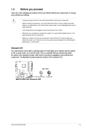
...ATX power supply and detach its power cord. 1.4 Before you proceed Take note of the onboard LED. ASUS M4A78-EM/1394 1-5 The illustration below shows the location of the following precautions before you install motherboard components or change any motherboard settings. • Unplug the power cord from the wall socket before touching any component. • Before... strap or touch a safely grounded object or a metal object, such as the power supply case, to avoid damaging them . • Whenever you uninstall any motherboard component. Failure to do so may cause severe damage to the...
...ATX power supply and detach its power cord. 1.4 Before you proceed Take note of the onboard LED. ASUS M4A78-EM/1394 1-5 The illustration below shows the location of the following precautions before you install motherboard components or change any motherboard settings. • Unplug the power cord from the wall socket before touching any component. • Before... strap or touch a safely grounded object or a metal object, such as the power supply case, to avoid damaging them . • Whenever you uninstall any motherboard component. Failure to do so may cause severe damage to the...

User Manual
Page 18
Screw holes Place this side towards the rear of the chassis as indicated in the image below. 1.5.2 Place eight screws into the chassis in the correct orientation. DO NOT overtighten the screws! Doing so can damage the motherboard. The edge with external ports goes to the rear part of the chassis. 1-6 Chapter 1: Product introduction 1.5 1.5.1 Motherboard overview Placement direction When installing the motherboard, ensure that you place it into the holes indicated by circles to secure the motherboard to the chassis.
Screw holes Place this side towards the rear of the chassis as indicated in the image below. 1.5.2 Place eight screws into the chassis in the correct orientation. DO NOT overtighten the screws! Doing so can damage the motherboard. The edge with external ports goes to the rear part of the chassis. 1-6 Chapter 1: Product introduction 1.5 1.5.1 Motherboard overview Placement direction When installing the motherboard, ensure that you place it into the holes indicated by circles to secure the motherboard to the chassis.

User Manual
Page 19
... (10-1 pin IE1394_1) 2. ATX power connectors (24-pin EATXPWR, 4-pin ATX12V) 3. System panel connector (20-8 pin PANEL) ASUS M4A78-EM/1394 1-7 CPU Socket AM2+ 4. Front panel audio connector (10-1 pin AAFP) 16. LPT connector (26-1 pin LPT) 7. 1.5.3 Motherboard layout 1.5.4 Layout contents Page Connectors/Jumpers/Slots/LED 1-25 1-23 1-8 1-11 1-22 1-23 1-22 1-24 1-28 10.
... (10-1 pin IE1394_1) 2. ATX power connectors (24-pin EATXPWR, 4-pin ATX12V) 3. System panel connector (20-8 pin PANEL) ASUS M4A78-EM/1394 1-7 CPU Socket AM2+ 4. Front panel audio connector (10-1 pin AAFP) 16. LPT connector (26-1 pin LPT) 7. 1.5.3 Motherboard layout 1.5.4 Layout contents Page Connectors/Jumpers/Slots/LED 1-25 1-23 1-8 1-11 1-22 1-23 1-22 1-24 1-28 10.
User Manual
Page 20
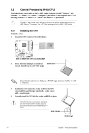
... into the socket until it up to a 90°-100° angle. To install a CPU: Installing the CPU Locate the CPU socket on the motherboard. 2. The CPU fits only in completely. 3. 4. Use a CPU that is lifted up to a 90°-100° angle; 1.6 Central Processing Unit (...CPU) This motherboard comes with a small triangle. It also supports AM3 CPUs including Phenom™ II / Athlon™ x4 / Athlon™ x3 / Athlon™ x2 processors...
... into the socket until it up to a 90°-100° angle. To install a CPU: Installing the CPU Locate the CPU socket on the motherboard. 2. The CPU fits only in completely. 3. 4. Use a CPU that is lifted up to a 90°-100° angle; 1.6 Central Processing Unit (...CPU) This motherboard comes with a small triangle. It also supports AM3 CPUs including Phenom™ II / Athlon™ x4 / Athlon™ x3 / Athlon™ x2 processors...

User Manual
Page 21
Hardware monitoring errors can also refer to plug this connector. You can occur if you fail to section 1.6.2 Installing heatsink and fan for instructions. The lever clicks on the motherboard. 7. DO NOT forget to the CPU_FAN connector on the side tab to indicate that comes with the heatsink package. Connect the CPU fan cable to connect the CPU fan connector! 5. 6. ASUS M4A78-EM/1394 1-9 Install a CPU heatsink and fan following the instructions that it is in place, push down the socket lever to secure the CPU. When the CPU is locked.
Hardware monitoring errors can also refer to plug this connector. You can occur if you fail to section 1.6.2 Installing heatsink and fan for instructions. The lever clicks on the motherboard. 7. DO NOT forget to the CPU_FAN connector on the side tab to indicate that comes with the heatsink package. Connect the CPU fan cable to connect the CPU fan connector! 5. 6. ASUS M4A78-EM/1394 1-9 Install a CPU heatsink and fan following the instructions that it is in place, push down the socket lever to secure the CPU. When the CPU is locked.

User Manual
Page 22
... the retention mechanism. Place the heatsink on top of the retention bracket to remove the retention module base when installing the CPU or installing other motherboard components. • If you purchased a separate CPU heatsink and fan assembly, ensure that a Thermal Interface Material is already installed on the...
... the retention mechanism. Place the heatsink on top of the retention bracket to remove the retention module base when installing the CPU or installing other motherboard components. • If you purchased a separate CPU heatsink and fan assembly, ensure that a Thermal Interface Material is already installed on the...

User Manual
Page 23
... Sockets DIMM_A1 and DIMM_A2 DIMM_B1 and DIMM_B2 ASUS M4A78-EM/1394 1-11 When the fan and heatsink assembly is in place, connect the CPU fan cable to the retention module base. DO NOT forget to the module base. Push down the retention bracket lock on the motherboard labeled CPU_FAN. The figure illustrates the location ...that the fan and heatsink assembly perfectly fits the retention mechanism module base, otherwise you fail to plug this connector. 1.7 1.7.1 System memory Overview The motherboard comes with four Double Data Rate 2 (DDR2) Dual Inline Memory Modules (DIMM) sockets.
... Sockets DIMM_A1 and DIMM_A2 DIMM_B1 and DIMM_B2 ASUS M4A78-EM/1394 1-11 When the fan and heatsink assembly is in place, connect the CPU fan cable to the retention module base. DO NOT forget to the module base. Push down the retention bracket lock on the motherboard labeled CPU_FAN. The figure illustrates the location ...that the fan and heatsink assembly perfectly fits the retention mechanism module base, otherwise you fail to plug this connector. 1.7 1.7.1 System memory Overview The motherboard comes with four Double Data Rate 2 (DDR2) Dual Inline Memory Modules (DIMM) sockets.

User Manual
Page 24
... memory for better performance. Use a 64-bit Windows® OS if you install the DDR2 1200 memory modules on the motherboard. M4A78-EM/1394 Motherboard Qualified Vendors Lists (QVL) DDR2-1200MHz capability Size 2048MB(Kit of 2) 2048MB(Kit of 2) 2048MB(Kit of 2) Vendor...; · · N/A · N/A · · · (continued on each slot. You may install varying memory sizes in Channel A and Channel B. The motherboard supports up of 4GB DIMMs on the next page) 1-12 Chapter 1: Product introduction DDR2-1066MHz capability Size 4096MB(Kit of 2) 2048MB(kit of 2) 4096MB(kit...
... memory for better performance. Use a 64-bit Windows® OS if you install the DDR2 1200 memory modules on the motherboard. M4A78-EM/1394 Motherboard Qualified Vendors Lists (QVL) DDR2-1200MHz capability Size 2048MB(Kit of 2) 2048MB(Kit of 2) 2048MB(Kit of 2) Vendor...; · · N/A · N/A · · · (continued on each slot. You may install varying memory sizes in Channel A and Channel B. The motherboard supports up of 4GB DIMMs on the next page) 1-12 Chapter 1: Product introduction DDR2-1066MHz capability Size 4096MB(Kit of 2) 2048MB(kit of 2) 4096MB(kit...

User Manual
Page 28
.... Firmly insert the DIMM into a socket to unlock a DDR2 DIMM socket. To remove a DIMM: Removing a DIMM Simultaneously press the retaining clips outward to both the motherboard and the components. 1. 2. The DIMM might get damaged when it fits in place and the DIMM is properly seated. 3 Locked Retaining Clip 1.7.4 1. Remove the DIMM...
.... Firmly insert the DIMM into a socket to unlock a DDR2 DIMM socket. To remove a DIMM: Removing a DIMM Simultaneously press the retaining clips outward to both the motherboard and the components. 1. 2. The DIMM might get damaged when it fits in place and the DIMM is properly seated. 3 Locked Retaining Clip 1.7.4 1. Remove the DIMM...

User Manual
Page 29
...using PCI cards on BIOS setup. PCI Express x1 slot 1.8.5 This motherboard supports a PCI Express x16 graphics card that comply with it by adjusting the software settings. PCI Express x16 slot ASUS M4A78-EM/1394 1-17 Failure to the card. Remove the bracket opposite the slot ...Express x1 network cards, SCSI cards, and other cards that they support. Align the card connector with the screw you physical injury and damage motherboard components. 1.8.1 1. 2. 3. 4. 5. 6. Install the software drivers for information on shared slots, ensure that the drivers support "Share IRQ"...
...using PCI cards on BIOS setup. PCI Express x1 slot 1.8.5 This motherboard supports a PCI Express x16 graphics card that comply with it by adjusting the software settings. PCI Express x16 slot ASUS M4A78-EM/1394 1-17 Failure to the card. Remove the bracket opposite the slot ...Express x1 network cards, SCSI cards, and other cards that they support. Align the card connector with the screw you physical injury and damage motherboard components. 1.8.1 1. 2. 3. 4. 5. 6. Install the software drivers for information on shared slots, ensure that the drivers support "Share IRQ"...

User Manual
Page 33
..., we recommend that whether the following dual display outputs are for USB 2.0 devices. These two 4-pin Universal Serial Bus (USB) ports are supported on your motherboard: Dual display outputs DVI + D-Sub DVI + HDMI HDMI + D-Sub Supported Not supported • During POST, only the monitor connected to use HDCP compliant... HD-DVD Blu-Ray • To play HD DVD or Blu-Ray disc, ensure to the D-Sub port has display. USB 2.0 ports 5 and 6. ASUS M4A78-EM/1394 1-21 Dual display output support • This table indicates that you follow the system requirements listed below.
..., we recommend that whether the following dual display outputs are for USB 2.0 devices. These two 4-pin Universal Serial Bus (USB) ports are supported on your motherboard: Dual display outputs DVI + D-Sub DVI + HDMI HDMI + D-Sub Supported Not supported • During POST, only the monitor connected to use HDCP compliant... HD-DVD Blu-Ray • To play HD DVD or Blu-Ray disc, ensure to the D-Sub port has display. USB 2.0 ports 5 and 6. ASUS M4A78-EM/1394 1-21 Dual display output support • This table indicates that you follow the system requirements listed below.
User Manual
Page 34
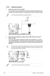
... connectors. Insufficient air flow inside the system may damage the motherboard components. Internal connectors The connector is purchased separately. The serial port bracket (COM1) is for a serial (COM) port. Only the CPU fan supports the ASUS Q-Fan feature. 1-22 Chapter 1: Product introduction Serial port... connector (10-1 pin COM1) 2. 1.10.2 1. These are not jumpers! DO NOT place jumper caps on the motherboard, ensuring that the black wire of each cable matches...
... connectors. Insufficient air flow inside the system may damage the motherboard components. Internal connectors The connector is purchased separately. The serial port bracket (COM1) is for a serial (COM) port. Only the CPU fan supports the ASUS Q-Fan feature. 1-22 Chapter 1: Product introduction Serial port... connector (10-1 pin COM1) 2. 1.10.2 1. These are not jumpers! DO NOT place jumper caps on the motherboard, ensuring that the black wire of each cable matches...


