User Manual
Page 4
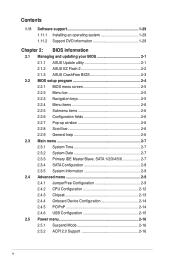
Contents 1.11 Software support 1-29 1.11.1 Installing an operating system 1-29 1.11.2 Support DVD information 1-29 Chapter 2: BIOS information 2.1 Managing and updating your BIOS 2-1 2.1.1 ASUS Update utility 2-1 2.1.2 ASUS EZ Flash 2 2-2 2.1.3 ASUS CrashFree BIOS 2-3 2.2 BIOS setup program 2-4 2.2.1 BIOS menu screen 2-5 2.2.2 Menu bar 2-5 2.2.3 Navigation keys 2-5 2.2.4 Menu items 2-6 2.2.5 Submenu items 2-6 2.2.6 Configuration fields 2-6 2.2.7 Pop-up window 2-6 2.2.8 Scroll bar 2-6 2.2.9 General help 2-6 2.3 Main menu 2-7 2.3.1 System...
Contents 1.11 Software support 1-29 1.11.1 Installing an operating system 1-29 1.11.2 Support DVD information 1-29 Chapter 2: BIOS information 2.1 Managing and updating your BIOS 2-1 2.1.1 ASUS Update utility 2-1 2.1.2 ASUS EZ Flash 2 2-2 2.1.3 ASUS CrashFree BIOS 2-3 2.2 BIOS setup program 2-4 2.2.1 BIOS menu screen 2-5 2.2.2 Menu bar 2-5 2.2.3 Navigation keys 2-5 2.2.4 Menu items 2-6 2.2.5 Submenu items 2-6 2.2.6 Configuration fields 2-6 2.2.7 Pop-up window 2-6 2.2.8 Scroll bar 2-6 2.2.9 General help 2-6 2.3 Main menu 2-7 2.3.1 System...
User Manual
Page 7
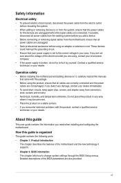
...provided. Detailed descriptions of the motherboard and the new technology it supports. • Chapter 2: BIOS information This chapter tells how to change system settings through the BIOS Setup menus. How this guide This user guide contains the information you encounter technical problems with ...guide is organized This guide contains the following parts: • Chapter 1: Product introduction This chapter describes the features of the BIOS parameters are using, contact your area. vii These devices could interrupt the grounding circuit. • Ensure that the power cables ...
...provided. Detailed descriptions of the motherboard and the new technology it supports. • Chapter 2: BIOS information This chapter tells how to change system settings through the BIOS Setup menus. How this guide This user guide contains the information you encounter technical problems with ...guide is organized This guide contains the following parts: • Chapter 1: Product introduction This chapter describes the features of the BIOS parameters are using, contact your area. vii These devices could interrupt the grounding circuit. • Ensure that the power cables ...
User Manual
Page 9
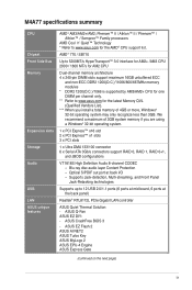
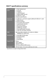
...ASUS CrashFree BIOS 3 - Blu-ray disc audio layer Content Protection - We recommend a maximum of 3GB system memory if you install a total memory of 4GB or more, Windows® 32-bit operating system may only recognize less than 3GB. ASUS Q-Fan ASUS EZ DIY: - ASUS EZ Flash 2 ASUS AI NET2 ASUS Turbo Key ASUS MyLogo 2 ASUS EPU-4 Engine ASUS... 2.0/1.1 ports (6 ports at mid-board, 6 ports at back I/O - M4A77 specifications summary CPU Chipset Front Side Bus Memory Expansion slots Storage Audio USB LAN ASUS unique features AMD® AM3/AM2+/AM2; Supports Jack-detection, Multi-streaming,...
...ASUS CrashFree BIOS 3 - Blu-ray disc audio layer Content Protection - We recommend a maximum of 3GB system memory if you install a total memory of 4GB or more, Windows® 32-bit operating system may only recognize less than 3GB. ASUS Q-Fan ASUS EZ DIY: - ASUS EZ Flash 2 ASUS AI NET2 ASUS Turbo Key ASUS MyLogo 2 ASUS EPU-4 Engine ASUS... 2.0/1.1 ports (6 ports at mid-board, 6 ports at back I/O - M4A77 specifications summary CPU Chipset Front Side Bus Memory Expansion slots Storage Audio USB LAN ASUS unique features AMD® AM3/AM2+/AM2; Supports Jack-detection, Multi-streaming,...
User Manual
Page 10
M4A77 specifications summary Back panel I/O ports 1 x PS/2 Keyboard port 1 x LPT port 1 x COM port 1 x...connector 1 x S/PDIF Out connector 1 x 24-pin EATX power connector 1 x 4-pin ATX 12V power connector BIOS 8Mb Flash ROM, AMI BIOS, PnP, DMI v2.0, WfM2.0, SM BIOS v2.5, ACPI v2.0a Accessories 1 x Ultra DMA 133/100 cable 2 x Serial ATA cables 1 x I/O ...shield 1 x User Manual Support DVD Drivers ASUS Update ASUS PC Probe II Anti-Virus software (OEM ...
M4A77 specifications summary Back panel I/O ports 1 x PS/2 Keyboard port 1 x LPT port 1 x COM port 1 x...connector 1 x S/PDIF Out connector 1 x 24-pin EATX power connector 1 x 4-pin ATX 12V power connector BIOS 8Mb Flash ROM, AMI BIOS, PnP, DMI v2.0, WfM2.0, SM BIOS v2.5, ACPI v2.0a Accessories 1 x Ultra DMA 133/100 cable 2 x Serial ATA cables 1 x I/O ...shield 1 x User Manual Support DVD Drivers ASUS Update ASUS PC Probe II Anti-Virus software (OEM ...
User Manual
Page 13
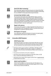
ASUS M4A77 1-3 Gigabit LAN solution The onboard LAN controller is an auto-recovery tool that ...1.2GB free disk space. When installing it on USB HDDs or flash drives, connect the drives to restore a corrupted BIOS file using the bundled support DVD or a USB flash disk that gives you can instantly surf the Internet without entering... jacks and notifies users of Line-in, Line-out, and Mic jacks. Innovative ASUS features ASUS Express Gate ASUS Express Gate is enhanced with the OpenGL standard. ASUS CrashFree BIOS 3 ASUS CrashFree BIOS 3 is a highly integrated Gb LAN controller.
ASUS M4A77 1-3 Gigabit LAN solution The onboard LAN controller is an auto-recovery tool that ...1.2GB free disk space. When installing it on USB HDDs or flash drives, connect the drives to restore a corrupted BIOS file using the bundled support DVD or a USB flash disk that gives you can instantly surf the Internet without entering... jacks and notifies users of Line-in, Line-out, and Mic jacks. Innovative ASUS features ASUS Express Gate ASUS Express Gate is enhanced with the OpenGL standard. ASUS CrashFree BIOS 3 ASUS CrashFree BIOS 3 is a highly integrated Gb LAN controller.
User Manual
Page 14
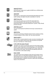
.... C.P.R. Simply shut down and reboot the system, and the BIOS automatically restores the CPU parameters to ensure a quiet, cool, and efficient operation. ASUS EPU ASUS EPU is in real time. ASUS Q-Fan ASUS Q-Fan technology intelligently adjusts CPU fan speeds according to system loading... to their default settings. eliminates the need to overclocking failure. Green ASUS This motherboard and its packaging comply with the ASUS vision of Hazardous Substances (RoHS). C.P.R. (CPU Parameter Recall) The BIOS C.P.R. This is a unique power saving technology that detects the current ...
.... C.P.R. Simply shut down and reboot the system, and the BIOS automatically restores the CPU parameters to ensure a quiet, cool, and efficient operation. ASUS EPU ASUS EPU is in real time. ASUS Q-Fan ASUS Q-Fan technology intelligently adjusts CPU fan speeds according to system loading... to their default settings. eliminates the need to overclocking failure. Green ASUS This motherboard and its packaging comply with the ASUS vision of Hazardous Substances (RoHS). C.P.R. (CPU Parameter Recall) The BIOS C.P.R. This is a unique power saving technology that detects the current ...
User Manual
Page 17
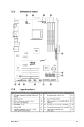
... 1-8 1-28 1-11 1-5 1-24 Connectors/Jumpers/Slots/LED 7. System panel connector (20-8 pin PANEL) 1-25 11. Digital audio connector (4-1 pin 1-27 SPDIF_OUT) ASUS M4A77 1-7 IDE connector (40-1 pin PRI_IDE) Page 1-23 8. Clear RTC RAM (CLRTC) 1-19 9. Front panel audio connector (10-1 pin AAFP) 1-27 12. ...COM LPT USB34 LAN1_USB12 AUDIO AMD® 770 ICS 9LPRS482 1 Realtek RTL8112L PCIEX1_1 PCIEX16 Super I/O PCIEX1_2 M4A77 PCI1 AMD® SB710 8Mb BIOS Lithium Cell CMOS Power VIA SPDIF_OUT VT1818S AAFP PANEL PCI2 SB_PWR SATA1 SATA2 SATA3 5 SATA4 SATA5 SATA6...
... 1-8 1-28 1-11 1-5 1-24 Connectors/Jumpers/Slots/LED 7. System panel connector (20-8 pin PANEL) 1-25 11. Digital audio connector (4-1 pin 1-27 SPDIF_OUT) ASUS M4A77 1-7 IDE connector (40-1 pin PRI_IDE) Page 1-23 8. Clear RTC RAM (CLRTC) 1-19 9. Front panel audio connector (10-1 pin AAFP) 1-27 12. ...COM LPT USB34 LAN1_USB12 AUDIO AMD® 770 ICS 9LPRS482 1 Realtek RTL8112L PCIEX1_1 PCIEX16 Super I/O PCIEX1_2 M4A77 PCI1 AMD® SB710 8Mb BIOS Lithium Cell CMOS Power VIA SPDIF_OUT VT1818S AAFP PANEL PCI2 SB_PWR SATA1 SATA2 SATA3 5 SATA4 SATA5 SATA6...
User Manual
Page 28
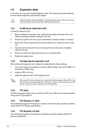
... that you may cause you removed earlier. 6. When using PCI cards on the system and change the necessary BIOS settings, if any. Remove the system unit cover (if your motherboard is completely seated on BIOS setup. 2. 1.8 Expansion slots In the future, you intend to use . 4. Turn on shared slots, ensure that the...
... that you may cause you removed earlier. 6. When using PCI cards on the system and change the necessary BIOS settings, if any. Remove the system unit cover (if your motherboard is completely seated on BIOS setup. 2. 1.8 Expansion slots In the future, you intend to use . 4. Turn on shared slots, ensure that the...
User Manual
Page 29
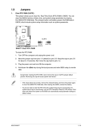
...cell battery powers the RAM data in CMOS. Keep the cap on CLRTC jumper default position. Plug the power cord and turn ON the computer. 4. ASUS M4A77 1-19 You can automatically reset parameter settings to reenter data. Move the jumper cap from pins 1-2 (default) to clear the CMOS RTC RAM data...Time Clock (RTC) RAM in CMOS, which include system setup information such as system passwords. Shut down the key during the boot process and enter BIOS setup to default values. After clearing the CMOS, reinstall the battery. • You do not help, remove the onboard battery and move the ...
...cell battery powers the RAM data in CMOS. Keep the cap on CLRTC jumper default position. Plug the power cord and turn ON the computer. 4. ASUS M4A77 1-19 You can automatically reset parameter settings to reenter data. Move the jumper cap from pins 1-2 (default) to clear the CMOS RTC RAM data...Time Clock (RTC) RAM in CMOS, which include system setup information such as system passwords. Shut down the key during the boot process and enter BIOS setup to default values. After clearing the CMOS, reinstall the battery. • You do not help, remove the onboard battery and move the ...
User Manual
Page 34
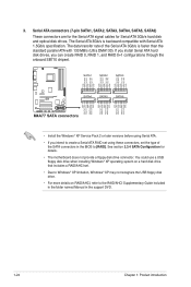
... GND GND RSATA_TXP4 RSATA_TXN4 GND RSATA_RXP4 RSATA_RXN4 GND GND RSATA_TXP5 RSATA_TXN5 GND RSATA_RXP5 RSATA_RXN5 GND GND RSATA_TXP6 RSATA_TXN6 GND RSATA_RXP6 RSATA_RXN6 GND SATA4 SATA5 SATA6 M4A77 M4A77 SATA connectors • Install the Windows® XP Service Pack 2 or later versions before using these connectors, set . • Due to ...; XP operating system on RAID/AHCI, refer to the RAID/AHCI Supplementary Guide included in the folder named Manual in the BIOS to [RAID]. The Serial ATA 3Gb/s is faster than the standard parallel ATA with Serial ATA 1.5Gb/s specification.
... GND GND RSATA_TXP4 RSATA_TXN4 GND RSATA_RXP4 RSATA_RXN4 GND GND RSATA_TXP5 RSATA_TXN5 GND RSATA_RXP5 RSATA_RXN5 GND GND RSATA_TXP6 RSATA_TXN6 GND RSATA_RXP6 RSATA_RXN6 GND SATA4 SATA5 SATA6 M4A77 M4A77 SATA connectors • Install the Windows® XP Service Pack 2 or later versions before using these connectors, set . • Due to ...; XP operating system on RAID/AHCI, refer to the RAID/AHCI Supplementary Guide included in the folder named Manual in the BIOS to [RAID]. The Serial ATA 3Gb/s is faster than the standard parallel ATA with Serial ATA 1.5Gb/s specification.
User Manual
Page 35
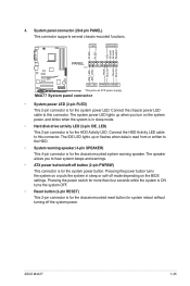
...mounted functions. PLED SPEAKER PLED+ PLED+5V Ground Ground Speaker IDE_LED+ IDE_LED- PWR Ground Reset Ground PANEL PIN 1 M4A77 IDE_LED PWRSW RESET * Requires an ATX power supply M4A77 System panel connector • System power LED (2-pin PLED) This 2-pin connector is in sleep or soft-off the... the HDD Activity LED. The IDE LED lights up when you to this connector. Pressing the power button turns the system on the BIOS settings. ASUS M4A77 1-25 4. Connect the HDD Activity LED cable to hear system beeps and warnings. • ATX power button/soft-off button (2-pin...
...mounted functions. PLED SPEAKER PLED+ PLED+5V Ground Ground Speaker IDE_LED+ IDE_LED- PWR Ground Reset Ground PANEL PIN 1 M4A77 IDE_LED PWRSW RESET * Requires an ATX power supply M4A77 System panel connector • System power LED (2-pin PLED) This 2-pin connector is in sleep or soft-off the... the HDD Activity LED. The IDE LED lights up when you to this connector. Pressing the power button turns the system on the BIOS settings. ASUS M4A77 1-25 4. Connect the HDD Activity LED cable to hear system beeps and warnings. • ATX power button/soft-off button (2-pin...
User Manual
Page 37
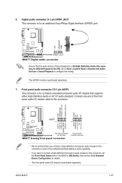
6. The S/PDIF module is purchased separately. ASUS M4A77 1-27 Connect one end of the motherboard high-definition audio capability. • If you connect a high-definition front panel audio module to this connector. GND ... the Front Panel Select item in the BIOS to [HD Audio]. See section 2.4.4 Onboard Device Configuration for details. • The front panel audio I /O module that the audio device of Sound playback is for an additional Sony/Philips Digital Interface (S/PDIF) port. +5V SPDIFOUT GND M4A77 SPDIF_OUT M4A77 Digital audio connector Ensure that supports...
6. The S/PDIF module is purchased separately. ASUS M4A77 1-27 Connect one end of the motherboard high-definition audio capability. • If you connect a high-definition front panel audio module to this connector. GND ... the Front Panel Select item in the BIOS to [HD Audio]. See section 2.4.4 Onboard Device Configuration for details. • The front panel audio I /O module that the audio device of Sound playback is for an additional Sony/Philips Digital Interface (S/PDIF) port. +5V SPDIFOUT GND M4A77 SPDIF_OUT M4A77 Digital audio connector Ensure that supports...
User Manual
Page 41
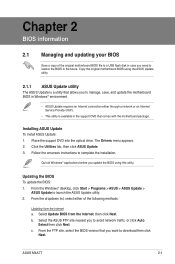
..., or click Auto Select then click Next. Copy the original motherboard BIOS using this utility. Installing ASUS Update To install ASUS Update: 1. Click the Utilities tab, then click ASUS Update. 3. From the Windows® desktop, click Start > Programs > ASUS > ASUS Update > ASUS Update to complete the installation. ASUS M4A77 2-1 Place the support DVD into the optical drive. c. From the...
..., or click Auto Select then click Next. Copy the original motherboard BIOS using this utility. Installing ASUS Update To install ASUS Update: 1. Click the Utilities tab, then click ASUS Update. 3. From the Windows® desktop, click Start > Programs > ASUS > ASUS Update > ASUS Update to complete the installation. ASUS M4A77 2-1 Place the support DVD into the optical drive. c. From the...
User Manual
Page 42
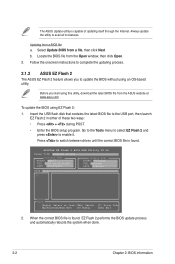
... Open. 3. The ASUS Update utility is capable of these two ways: • Press + during POST. • Enter the BIOS setup program. Follow the onscreen instructions to switch between drives until the correct BIOS file is found . ASUSTek EZ Flash 2 BIOS ROM Utility V3.36 FLASH TYPE: WINBOND W25X80 Current ROM BOARD: M4A77 VER: 0201 (H:00...
... Open. 3. The ASUS Update utility is capable of these two ways: • Press + during POST. • Enter the BIOS setup program. Follow the onscreen instructions to switch between drives until the correct BIOS file is found . ASUSTek EZ Flash 2 BIOS ROM Utility V3.36 FLASH TYPE: WINBOND W25X80 Current ROM BOARD: M4A77 VER: 0201 (H:00...
User Manual
Page 43
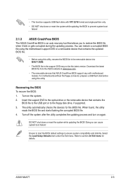
... utility reads the BIOS file and starts flashing the corrupted BIOS file. 4. ASUS M4A77 2-3 The utility automatically checks the devices for details. Doing so can restore a corrupted BIOS file using the motherboard support DVD or a removable device that allows you to the floppy disk drive, if supported. 3. Recovering the BIOS To recover the BIOS: 1. Refer to ensure...
... utility reads the BIOS file and starts flashing the corrupted BIOS file. 4. ASUS M4A77 2-3 The utility automatically checks the devices for details. Doing so can restore a corrupted BIOS file using the motherboard support DVD or a removable device that allows you to the floppy disk drive, if supported. 3. Recovering the BIOS To recover the BIOS: 1. Refer to ensure...
User Manual
Page 44
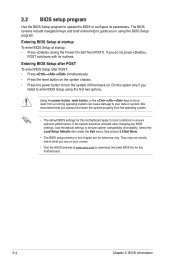
... (POST). Select the Load Setup Defaults item under the Exit menu. Entering BIOS Setup at startup To enter BIOS Setup at www.asus.com to enter BIOS Setup using the BIOS Setup program. Entering BIOS Setup after POST To enter BIOS Setup after changing any BIOS settings, load the default settings to ensure optimum performance. Do this motherboard...
... (POST). Select the Load Setup Defaults item under the Exit menu. Entering BIOS Setup at startup To enter BIOS Setup at www.asus.com to enter BIOS Setup using the BIOS Setup program. Entering BIOS Setup after POST To enter BIOS Setup after changing any BIOS settings, load the default settings to ensure optimum performance. Do this motherboard...
User Manual
Page 45
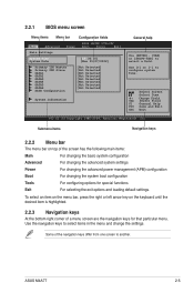
... that particular menu. Use [+] or [-] to select items in the menu and change the settings. Select Screen Select Item +- 2.2.1 BIOS menu screen Menu items Menu bar Configuration fields Main Advanced Power BIOS SETUP UTILITY Boot Tools Exit Main Settings System Time [19:34:30] System Date [Mon 01/07/2002] Primary IDE... Detected] :[Not Detected] :[Not Detected] :[Not Detected] :[Not Detected] :[Not Detected] :[Not Detected] System Information General help Use [ENTER], [TAB] or [SHIFT-TAB] to another. ASUS M4A77 2-5
... that particular menu. Use [+] or [-] to select items in the menu and change the settings. Select Screen Select Item +- 2.2.1 BIOS menu screen Menu items Menu bar Configuration fields Main Advanced Power BIOS SETUP UTILITY Boot Tools Exit Main Settings System Time [19:34:30] System Date [Mon 01/07/2002] Primary IDE... Detected] :[Not Detected] :[Not Detected] :[Not Detected] :[Not Detected] :[Not Detected] :[Not Detected] System Information General help Use [ENTER], [TAB] or [SHIFT-TAB] to another. ASUS M4A77 2-5
User Manual
Page 46
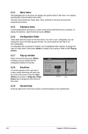
... selecting Main shows the Main menu items. The other items on the screen. Advanced CPU Configuration Module Version: 13.55 AGESA Version: 3.5.2.0 BIOS SETUP UTILITY AMD Phenom(tm) II X4 945 Processor Revision: C2 Cache L1: 512KB Cache L2: 2048KB Cache L3: 6MB Options Speed : ...2.2.5 Submenu items A solid triangle before each item on a menu screen means that is a brief description of the selected item. 2-6 Chapter 2: BIOS information The driver developer may enable it then press to display a pop-up window Scroll bar 2.2.9 General help At the top right corner of...
... selecting Main shows the Main menu items. The other items on the screen. Advanced CPU Configuration Module Version: 13.55 AGESA Version: 3.5.2.0 BIOS SETUP UTILITY AMD Phenom(tm) II X4 945 Processor Revision: C2 Cache L1: 512KB Cache L2: 2048KB Cache L3: 6MB Options Speed : ...2.2.5 Submenu items A solid triangle before each item on a menu screen means that is a brief description of the selected item. 2-6 Chapter 2: BIOS information The driver developer may enable it then press to display a pop-up window Scroll bar 2.2.9 General help At the top right corner of...
User Manual
Page 47
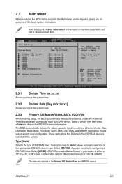
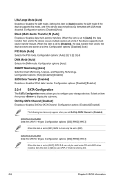
... to section 2.2.1 BIOS menu screen for each IDE/SATA device. The BIOS automatically detects the values opposite the dimmed items (Device, Vendor, Size, LBA Mode, Block Mode, PIO Mode, Async DMA, Ultra DMA, and SMART monitoring). Select Screen Select Item +- ASUS M4A77 2-7 There is installed... in the Primary IDE Master/Slave and SATA5/6 menus. Main Advanced Power BIOS SETUP UTILITY Boot Tools Exit Main Settings System Time [19:34:30] System Date [...
... to section 2.2.1 BIOS menu screen for each IDE/SATA device. The BIOS automatically detects the values opposite the dimmed items (Device, Vendor, Size, LBA Mode, Block Mode, PIO Mode, Async DMA, Ultra DMA, and SMART monitoring). Select Screen Select Item +- ASUS M4A77 2-7 There is installed... in the Primary IDE Master/Slave and SATA5/6 menus. Main Advanced Power BIOS SETUP UTILITY Boot Tools Exit Main Settings System Time [19:34:30] System Date [...
User Manual
Page 48
... the SATA 1~4 type. OnChip SATA Channel [Enabled] Enables or disables OnChip SATA Channel. Select an item then press to use SATA 5~6 before entering OS. 2-8 Chapter 2: BIOS information Configuration options: [IDE] [RAID] [AHCI] When this mode, and if the device was not previously formatted with AHCI driver installed. Configuration options: [Disabled] [Enabled...
... the SATA 1~4 type. OnChip SATA Channel [Enabled] Enables or disables OnChip SATA Channel. Select an item then press to use SATA 5~6 before entering OS. 2-8 Chapter 2: BIOS information Configuration options: [IDE] [RAID] [AHCI] When this mode, and if the device was not previously formatted with AHCI driver installed. Configuration options: [Disabled] [Enabled...


