
User Manual
Page 1
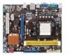
M2N68-AM SE Motherboard
M2N68-AM SE Motherboard
User Manual
Page 3
Contents Notices...v Safety information vi About this guide vi M2N68-AM SE specifications summary viii Chapter 1: Product introduction 1.1 Before you proceed 1-1 1.2 Motherboard overview 1-2 1.2.1 Motherboard layout 1-2 1.2.2 Layout contents 1-2 1.3 Central Processing Unit (CPU 1-3 1.4 System memory 1-3... 1-8 1.7 Connectors 1-9 1.7.1 Rear panel ports 1-9 1.7.2 Internal connectors 1-10 1.8 Software support 1-15 1.8.1 Installing an operating system 1-15 1.8.2 Support DVD information 1-15 1.8.3 ASUS Express Gate 1-16 Chapter 2: BIOS information 2.1 Managing and updating your BIOS...
Contents Notices...v Safety information vi About this guide vi M2N68-AM SE specifications summary viii Chapter 1: Product introduction 1.1 Before you proceed 1-1 1.2 Motherboard overview 1-2 1.2.1 Motherboard layout 1-2 1.2.2 Layout contents 1-2 1.3 Central Processing Unit (CPU 1-3 1.4 System memory 1-3... 1-8 1.7 Connectors 1-9 1.7.1 Rear panel ports 1-9 1.7.2 Internal connectors 1-10 1.8 Software support 1-15 1.8.1 Installing an operating system 1-15 1.8.2 Support DVD information 1-15 1.8.3 ASUS Express Gate 1-16 Chapter 2: BIOS information 2.1 Managing and updating your BIOS...
User Manual
Page 8
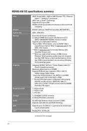
M2N68-AM SE specifications summary CPU Chipset System bus Memory Graphics Expansion slots Storage Audio USB LAN ...High Definition Audio 6-channel CODEC Supports Jack-detection and Multi-streaming Supports up to 4GB system memory * Due to www.asus.com for the AM2+ CPU models. ** Refer to AM2+ CPU limitation, only one DDR2 1066 is recommended if you... install a total memory of less than 3GB. Refer to www.asus.com for the latest Memory QVL (Qualified Vendors List). *** When you are using a Windows 32-bit operating system. Hence...
M2N68-AM SE specifications summary CPU Chipset System bus Memory Graphics Expansion slots Storage Audio USB LAN ...High Definition Audio 6-channel CODEC Supports Jack-detection and Multi-streaming Supports up to 4GB system memory * Due to www.asus.com for the AM2+ CPU models. ** Refer to AM2+ CPU limitation, only one DDR2 1066 is recommended if you... install a total memory of less than 3GB. Refer to www.asus.com for the latest Memory QVL (Qualified Vendors List). *** When you are using a Windows 32-bit operating system. Hence...
User Manual
Page 9
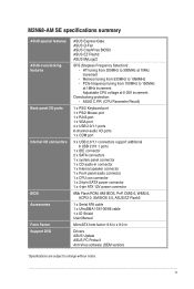
...Overclocking protection: - ix Memory tuning from 200MHz to 150MHz at 1MHz increment Adjustable CPU voltage at 1MHz increment - M2N68-AM SE specifications summary ASUS special features ASUS overclocking features Back panel I/O ports Internal I /O ports 1 x COM port 3 x USB 2.0/1.1 connectors support ...133/100/66 cable 1 x IO Shield User Manual MicroATX form factor: 9.6 in x 8.0 in Drivers ASUS Update ASUS PC Probe II Anti-Virus software (OEM version) *Specifications are subject to 1066MHz - ASUS C.P.R. (CPU Parameter Recall) 1 x PS/2 Keyboard port 1 x PS/2 Mouse port 1 x RJ45 ...
...Overclocking protection: - ix Memory tuning from 200MHz to 150MHz at 1MHz increment Adjustable CPU voltage at 1MHz increment - M2N68-AM SE specifications summary ASUS special features ASUS overclocking features Back panel I/O ports Internal I /O ports 1 x COM port 3 x USB 2.0/1.1 connectors support ...133/100/66 cable 1 x IO Shield User Manual MicroATX form factor: 9.6 in x 8.0 in Drivers ASUS Update ASUS PC Probe II Anti-Virus software (OEM version) *Specifications are subject to 1066MHz - ASUS C.P.R. (CPU Parameter Recall) 1 x PS/2 Keyboard port 1 x PS/2 Mouse port 1 x RJ45 ...
User Manual
Page 10
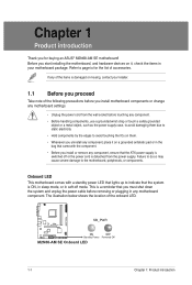
... in any motherboard settings. • Unplug the power cord from the power supply. M2N68-AM SE SB_PWR ON OFF Standby Power Powered Off M2N68-AM SE Onboard LED 1-1 Chapter 1: Product introduction Refer to page ix for buying an ASUS® M2N68-AM SE motherboard! Onboard LED This motherboard comes with the component. • Before you install or...
... in any motherboard settings. • Unplug the power cord from the power supply. M2N68-AM SE SB_PWR ON OFF Standby Power Powered Off M2N68-AM SE Onboard LED 1-1 Chapter 1: Product introduction Refer to page ix for buying an ASUS® M2N68-AM SE motherboard! Onboard LED This motherboard comes with the component. • Before you install or...
User Manual
Page 11
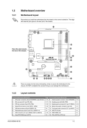
.../LED 1-13 9. Optical drive audio connector (4-pin CD) 1-8 13. PCIe x16/PCIe x1/PCI slot Page 1-13 1-1 1-14 1-11 1-14 1-3 1-3 1-7 ASUS M2N68-AM SE 1-2 KBMS ATX12V 1 20.3cm(8.0in) COM EATXPWR DDR2 DIMM_A1 (64bit, 240-pin module) DDR2 DIMM_B1 (64bit, 240-pin module) SOCKET AM2 VGA 14 Place this... motherboard to the rear part of the chassis. 16 15 USB34 24.4cm(9.6in) LAN1_USB12 AUDIO RTL 8201CP USBPW1-4 Super I/O CPU_FAN M2N68-AM SE PCIEX16 Lithium Cell CMOS Power PCIEX1_1 NVIDIA® MCP68PVNT PRI_IDE SATA1 SATA2 ALC 662 CD AAFP 13 12 PCI1 F_PANEL SB_PWR CLRTC SPEAKER...
.../LED 1-13 9. Optical drive audio connector (4-pin CD) 1-8 13. PCIe x16/PCIe x1/PCI slot Page 1-13 1-1 1-14 1-11 1-14 1-3 1-3 1-7 ASUS M2N68-AM SE 1-2 KBMS ATX12V 1 20.3cm(8.0in) COM EATXPWR DDR2 DIMM_A1 (64bit, 240-pin module) DDR2 DIMM_B1 (64bit, 240-pin module) SOCKET AM2 VGA 14 Place this... motherboard to the rear part of the chassis. 16 15 USB34 24.4cm(9.6in) LAN1_USB12 AUDIO RTL 8201CP USBPW1-4 Super I/O CPU_FAN M2N68-AM SE PCIEX16 Lithium Cell CMOS Power PCIEX1_1 NVIDIA® MCP68PVNT PRI_IDE SATA1 SATA2 ALC 662 CD AAFP 13 12 PCI1 F_PANEL SB_PWR CLRTC SPEAKER...

User Manual
Page 12
... a 940-pin AM2+ / AM2 socket designed for the AMD Opteron™ processor. The figure illustrates the location of the DDR2 DIMM sockets: DIMM_A1 DIMM_B1 M2N68-AM SE M2N68-AM SE 240-pin DDR2 DIMM sockets Channel Channel A Channel B Sockets DIMM_A1 DIMM_B1 1-3 Chapter 1: Product introduction 1.3 Central Processing Unit (CPU) This motherboard comes with two Double...
... a 940-pin AM2+ / AM2 socket designed for the AMD Opteron™ processor. The figure illustrates the location of the DDR2 DIMM sockets: DIMM_A1 DIMM_B1 M2N68-AM SE M2N68-AM SE 240-pin DDR2 DIMM sockets Channel Channel A Channel B Sockets DIMM_A1 DIMM_B1 1-3 Chapter 1: Product introduction 1.3 Central Processing Unit (CPU) This motherboard comes with two Double...
User Manual
Page 13
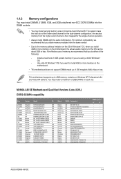
M2N68-AM SE Motherboard Qualified Vendors Lists (QVL) DDR2-533MHz capability Size 256MB 512MB 1G 256MB 512MB 256MB 1G 512MB 512MB 1G 512MB 512MB 1G 512MB 512MB 512MB ...; • • • • • • • • • • • • • • • • • • • • • • • • ASUS M2N68-AM SE 1-4 The system maps the total size of the lower-sized channel for the single-channel operation. • Always install DIMMs with the same CAS latency...
M2N68-AM SE Motherboard Qualified Vendors Lists (QVL) DDR2-533MHz capability Size 256MB 512MB 1G 256MB 512MB 256MB 1G 512MB 512MB 1G 512MB 512MB 1G 512MB 512MB 512MB ...; • • • • • • • • • • • • • • • • • • • • • • • • ASUS M2N68-AM SE 1-4 The system maps the total size of the lower-sized channel for the single-channel operation. • Always install DIMMs with the same CAS latency...

User Manual
Page 15
Under the default state, some memory modules for the latest QVL. ASUS M2N68-AM SE 1-6 DDR2-800MHz capability Size Vendor Model CL Brand SS/ DS Component 1G Kingston KVR800D2N5/1G N/A Samsung DS 1G Kingston KHX6400D2LL/1G N/A Kingston DS 512MB Kingston ... memory configuration. • B*: Supports one pair of modules inserted into both the yellow slots as one pair of accessing information from a memory module. Visit the ASUS website at www.asus.com for overclocking may operate at a lower frequency than the vendor-marked value.
Under the default state, some memory modules for the latest QVL. ASUS M2N68-AM SE 1-6 DDR2-800MHz capability Size Vendor Model CL Brand SS/ DS Component 1G Kingston KVR800D2N5/1G N/A Samsung DS 1G Kingston KHX6400D2LL/1G N/A Kingston DS 512MB Kingston ... memory configuration. • B*: Supports one pair of modules inserted into both the yellow slots as one pair of accessing information from a memory module. Visit the ASUS website at www.asus.com for overclocking may operate at a lower frequency than the vendor-marked value.
User Manual
Page 17
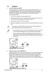
... enter BIOS setup to clear the CMOS RTC RAM data. The onboard button cell battery powers the RAM data in CMOS. M2N68-AM SE CLRTC 12 23 Normal (Default) M2N68-AM SE Clear RTC RAM Clear RTC 2. Set to +5VSB to overclocking. The USBPW5-10 jumper is for about 5-10 seconds,... the Real Time Clock (RTC) RAM in CMOS, which include system setup information such as system passwords. M2N68-AM SE USBPW5-10 12 23 +5V +5VSB (Default) M2N68-AM SE USB Device Wake Up ASUS M2N68-AM SE 1-8 1.6 Jumpers 1. Keep the cap on CLRTC jumper default position. Plug the power cord and turn ON...
... enter BIOS setup to clear the CMOS RTC RAM data. The onboard button cell battery powers the RAM data in CMOS. M2N68-AM SE CLRTC 12 23 Normal (Default) M2N68-AM SE Clear RTC RAM Clear RTC 2. Set to +5VSB to overclocking. The USBPW5-10 jumper is for about 5-10 seconds,... the Real Time Clock (RTC) RAM in CMOS, which include system setup information such as system passwords. M2N68-AM SE USBPW5-10 12 23 +5V +5VSB (Default) M2N68-AM SE USB Device Wake Up ASUS M2N68-AM SE 1-8 1.6 Jumpers 1. Keep the cap on CLRTC jumper default position. Plug the power cord and turn ON...
User Manual
Page 18
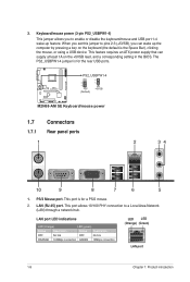
... for the rear USB ports. PS/2 Mouse port. This feature requires an ATX power supply that can wake up feature. PS2_USBPW1-4 12 23 M2N68-AM SE +5V (Default) +5VSB M2N68-AM SE Keyboard/mouse power 1.7 1.7.1 1 Connectors Rear panel ports 2 34 10 9 8 7 6 5 1. Keyboard/mouse power (3-pin PS2_USBPW1-4) This jumper allows you can supply at least...
... for the rear USB ports. PS/2 Mouse port. This feature requires an ATX power supply that can wake up feature. PS2_USBPW1-4 12 23 M2N68-AM SE +5V (Default) +5VSB M2N68-AM SE Keyboard/mouse power 1.7 1.7.1 1 Connectors Rear panel ports 2 34 10 9 8 7 6 5 1. Keyboard/mouse power (3-pin PS2_USBPW1-4) This jumper allows you can supply at least...
User Manual
Page 19
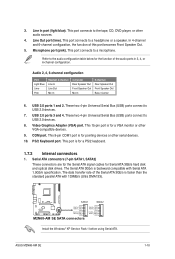
Line Out port (lime). Microphone port (pink). COM port. ASUS M2N68-AM SE 1-10 This port connects to a microphone. This port connects to a headphone or a speaker. Audio 2, 4, 6-channel configuration Port Light Blue Lime Pink ...PS/2 keyboard. 1.7.2 Internal connectors 1. The Serial ATA 3Gb/s is for pointing devices or other audio sources. 4. M2N68-AM SE SATA1 SATA2 GND RSATA_TXN1 RSATA_TXP1 GND RSATA_RXN1 RSATA_RXP1 GND M2N68-AM SE SATA connectors GND RSATA_TXN2 RSATA_TXP2 GND RSATA_RXN2 RSATA_RXP2 GND Install the Windows® XP Service Pack 1 before using Serial ATA...
Line Out port (lime). Microphone port (pink). COM port. ASUS M2N68-AM SE 1-10 This port connects to a microphone. This port connects to a headphone or a speaker. Audio 2, 4, 6-channel configuration Port Light Blue Lime Pink ...PS/2 keyboard. 1.7.2 Internal connectors 1. The Serial ATA 3Gb/s is for pointing devices or other audio sources. 4. M2N68-AM SE SATA1 SATA2 GND RSATA_TXN1 RSATA_TXP1 GND RSATA_RXN1 RSATA_RXP1 GND M2N68-AM SE SATA connectors GND RSATA_TXN2 RSATA_TXP2 GND RSATA_RXN2 RSATA_RXP2 GND Install the Windows® XP Service Pack 1 before using Serial ATA...
User Manual
Page 20
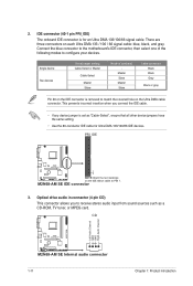
... is set as a CD-ROM, TV tuner, or MPEG card. PRI_IDE PIN1 M2N68-AM SE NOTE:Orient the red markings on the Ultra DMA cable connector. M2N68-AM SE IDE connector 3. CD Right Audio Channel Left Audio Channel GND GND M2N68-AM SE M2N68-AM SE Internal audio connector 1-11 Chapter 1: Product introduction Connect the blue connector to...
... is set as a CD-ROM, TV tuner, or MPEG card. PRI_IDE PIN1 M2N68-AM SE NOTE:Orient the red markings on the Ultra DMA cable connector. M2N68-AM SE IDE connector 3. CD Right Audio Channel Left Audio Channel GND GND M2N68-AM SE M2N68-AM SE Internal audio connector 1-11 Chapter 1: Product introduction Connect the blue connector to...

User Manual
Page 21
... 2.0 specification that the black wire of each cable matches the ground pin of the connector. M2N68-AM SE CPU_FAN CPU FAN PWM CPU FAN IN CPU FAN PWR GND M2N68-AM SE CPU fan connector ASUS M2N68-AM SE 1-12 Doing so will damage the motherboard! It is purchased separately. 5. The USB 2.0...+ GND NC USB+5V USB_P8USB_P8+ GND NC USB+5V USB_P6USB_P6+ GND NC M2N68-AM SE USB56 PIN 1 USB78 PIN 1 USB910 PIN 1 USB+5V USB_P9USB_P9+ GND USB+5V USB_P7USB_P7+ GND USB+5V USB_P5USB_P5+ GND M2N68-AM SE USB2.0 connectors Never connect a 1394 cable to the CPU fan connector on the...
... 2.0 specification that the black wire of each cable matches the ground pin of the connector. M2N68-AM SE CPU_FAN CPU FAN PWM CPU FAN IN CPU FAN PWR GND M2N68-AM SE CPU fan connector ASUS M2N68-AM SE 1-12 Doing so will damage the motherboard! It is purchased separately. 5. The USB 2.0...+ GND NC USB+5V USB_P8USB_P8+ GND NC USB+5V USB_P6USB_P6+ GND NC M2N68-AM SE USB56 PIN 1 USB78 PIN 1 USB910 PIN 1 USB+5V USB_P9USB_P9+ GND USB+5V USB_P7USB_P7+ GND USB+5V USB_P5USB_P5+ GND M2N68-AM SE USB2.0 connectors Never connect a 1394 cable to the CPU fan connector on the...

User Manual
Page 22
... SPEAKER) This 4-pin connector is inadequate. • DO NOT forget to hear system beeps and warnings. +5V GND GND Speaker Out M2N68-AM SE SPEAKER PIN 1 M2N68-AM SE Speaker Out Connector 1-13 Chapter 1: Product introduction The system may become unstable or may not boot up if the power is inadequate. &#...power output when configuring a system with 20-pin and 4-pin power plugs, ensure that the 20-pin power plug can provide at http://support.asus. otherwise, the system will not boot up if the power is for details. 7. 6. The plugs from the power supply are designed to ...
... SPEAKER) This 4-pin connector is inadequate. • DO NOT forget to hear system beeps and warnings. +5V GND GND Speaker Out M2N68-AM SE SPEAKER PIN 1 M2N68-AM SE Speaker Out Connector 1-13 Chapter 1: Product introduction The system may become unstable or may not boot up if the power is inadequate. &#...power output when configuring a system with 20-pin and 4-pin power plugs, ensure that the 20-pin power plug can provide at http://support.asus. otherwise, the system will not boot up if the power is for details. 7. 6. The plugs from the power supply are designed to ...
User Manual
Page 23
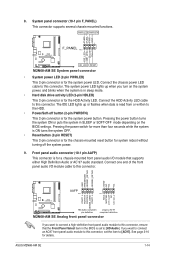
... AC`97 audio standard. Front panel audio connector (10-1 pin AAFP) This connector is set the item to this connector. Ground Reset M2N68-AM SE F_PANEL PIN 1 HD_LED RESET M2N68-AM SE System panel connector • System power LED (2-pin PWRLED) This 2-pin connector is for the chassis-mounted reset button for the system... system power LED lights up or flashes when data is read from or written to this connector. See page 2-10 for the HDD Activity LED. 8. ASUS M2N68-AM SE 1-14
... AC`97 audio standard. Front panel audio connector (10-1 pin AAFP) This connector is set the item to this connector. Ground Reset M2N68-AM SE F_PANEL PIN 1 HD_LED RESET M2N68-AM SE System panel connector • System power LED (2-pin PWRLED) This 2-pin connector is for the chassis-mounted reset button for the system... system power LED lights up or flashes when data is read from or written to this connector. See page 2-10 for the HDD Activity LED. 8. ASUS M2N68-AM SE 1-14
User Manual
Page 25
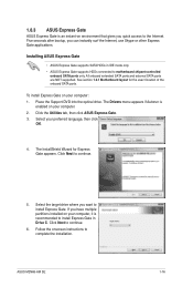
.... Follow the onscreen instructions to the Internet. Select the target drive where you can instantly surf the Internet, use Skype or other Express Gate applications. ASUS M2N68-AM SE 1-16 Click Next to install Express Gate. Place the Support DVD into the optical drive. Click the Utilities tab, then click...
.... Follow the onscreen instructions to the Internet. Select the target drive where you can instantly surf the Internet, use Skype or other Express Gate applications. ASUS M2N68-AM SE 1-16 Click Next to install Express Gate. Place the Support DVD into the optical drive. Click the Utilities tab, then click...
User Manual
Page 27
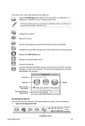
... you to set the login credentials such as the username, password, and SSID. • The number of the screen. Click an icon to close. ASUS M2N68-AM SE 1-18 Drag the window's title bar. Drag any RJ-45 port, and Express Gate automatically uses the available port. Also specify whether each port uses...
... you to set the login credentials such as the username, password, and SSID. • The number of the screen. Click an icon to close. ASUS M2N68-AM SE 1-18 Drag the window's title bar. Drag any RJ-45 port, and Express Gate automatically uses the available port. Also specify whether each port uses...
User Manual
Page 29
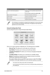
... environment, check the following: 1. Power off the computer. Configures the network. If a USB device is detected, the icon contains a green arrow. Displays the ASUS Utility panel. ASUS M2N68-AM SE Configuration Panel 1-20 Displays your Express Gate version. Adjusts the volume. Configures the LaunchBar settings such as auto-hide mode and docking position. Open...
... environment, check the following: 1. Power off the computer. Configures the network. If a USB device is detected, the icon contains a green arrow. Displays the ASUS Utility panel. ASUS M2N68-AM SE Configuration Panel 1-20 Displays your Express Gate version. Adjusts the volume. Configures the LaunchBar settings such as auto-hide mode and docking position. Open...
User Manual
Page 31
... hard drive or external storage devices. Refer to enable xDSL/cable dial-up which is enabled, the port it uses will automatically be unchecked. ASUS M2N68-AM SE 1-22 When PPPoE is referred to as WEPAUTO in the Encryption Type field, and key in the network name of the Advanced Network Settings box...
... hard drive or external storage devices. Refer to enable xDSL/cable dial-up which is enabled, the port it uses will automatically be unchecked. ASUS M2N68-AM SE 1-22 When PPPoE is referred to as WEPAUTO in the Encryption Type field, and key in the network name of the Advanced Network Settings box...


