
User Manual
Page 4
... 2.7.1 Rear panel connectors 2-30 2.7.2 Internal connectors 2-31 Chapter 3: Powering up 3.1 Starting up for the first time 3-3 3.2 Powering off the computer 3-4 3.2.1 Using the OS shut down function 3-4 3.2.2 Using the dual function power switch 3-4 Chapter 4: BIOS setup 4.1 Managing and updating your BIOS 4-3 4.1.1 ASUS EZ Flash 2 utility 4-3 4.1.2 BUPDATER utility 4-4 4.1.3 ASUS CrashFree BIOS 3 utility 4-6 4.2 BIOS setup program 4-7 4.2.1 BIOS menu...
... 2.7.1 Rear panel connectors 2-30 2.7.2 Internal connectors 2-31 Chapter 3: Powering up 3.1 Starting up for the first time 3-3 3.2 Powering off the computer 3-4 3.2.1 Using the OS shut down function 3-4 3.2.2 Using the dual function power switch 3-4 Chapter 4: BIOS setup 4.1 Managing and updating your BIOS 4-3 4.1.1 ASUS EZ Flash 2 utility 4-3 4.1.2 BUPDATER utility 4-4 4.1.3 ASUS CrashFree BIOS 3 utility 4-6 4.2 BIOS setup program 4-7 4.2.1 BIOS menu...

User Manual
Page 5
CDROM Drives 4-37 4.7.3 Boot Settings Configuration 4-38 4.7.4 Security 4-39 4.8 Tools menu 4-41 4.8.1 ASUS EZ Flash 2 4-41 4.9 Exit menu 4-42 Chapter 5: Driver installation 5.1 LAN driver installation 5-3 5.2 ATI SM Bus ... menu 4-15 4.4.1 CPU Configuration 4-15 4.4.2 Chipset Configuration 4-17 4.4.3 Onboard Devices Configuration 4-28 4.4.4 USB Configuration 4-29 4.4.5 PCIPnP 4-30 4.5 Server menu 4-31 4.6 Power menu 4-33 4.6.1 Suspend Mode 4-33 4.6.2 Repost Video on S3 Resume 4-33 4.6.3 ACPI 2.0 Support 4-33 4.6.4 ACPI APIC support 4-33 4.6.5 APM Configuration 4-34 4.6.6...
CDROM Drives 4-37 4.7.3 Boot Settings Configuration 4-38 4.7.4 Security 4-39 4.8 Tools menu 4-41 4.8.1 ASUS EZ Flash 2 4-41 4.9 Exit menu 4-42 Chapter 5: Driver installation 5.1 LAN driver installation 5-3 5.2 ATI SM Bus ... menu 4-15 4.4.1 CPU Configuration 4-15 4.4.2 Chipset Configuration 4-17 4.4.3 Onboard Devices Configuration 4-28 4.4.4 USB Configuration 4-29 4.4.5 PCIPnP 4-30 4.5 Server menu 4-31 4.6 Power menu 4-33 4.6.1 Suspend Mode 4-33 4.6.2 Repost Video on S3 Resume 4-33 4.6.3 ACPI 2.0 Support 4-33 4.6.4 ACPI APIC support 4-33 4.6.5 APM Configuration 4-34 4.6.6...

User Manual
Page 7
...wet. • Place the product on it by yourself. Safety information Electrical safety • To prevent electrical shock hazard, disconnect the power cable from the electrical outlet before relocating the system. • When adding or removing devices to or from the system, ensure that the... power cables for disposal of electronic products. These devices could interrupt the grounding circuit. • Make sure that the product (electrical, electronic ...
...wet. • Place the product on it by yourself. Safety information Electrical safety • To prevent electrical shock hazard, disconnect the power cable from the electrical outlet before relocating the system. • When adding or removing devices to or from the system, ensure that the... power cables for disposal of electronic products. These devices could interrupt the grounding circuit. • Make sure that the product (electrical, electronic ...

User Manual
Page 8
Where to find more information Refer to the ASUS contact information. 2. These documents are also provided. • Chapter 5: Driver installation This chapter provides instructions for installing the necessary drivers for product and software ...may have to change system settings through the BIOS Setup menus. ASUS websites The ASUS website provides updated information on the motherboard. • Chapter 3: Powering up This chapter describes the power up sequence and ways of the switches, jumpers, and connectors on ASUS hardware and software products. How this guide This user guide ...
Where to find more information Refer to the ASUS contact information. 2. These documents are also provided. • Chapter 5: Driver installation This chapter provides instructions for installing the necessary drivers for product and software ...may have to change system settings through the BIOS Setup menus. ASUS websites The ASUS website provides updated information on the motherboard. • Chapter 3: Powering up This chapter describes the power up sequence and ways of the switches, jumpers, and connectors on ASUS hardware and software products. How this guide This user guide ...

User Manual
Page 11
KGPE-D16 specifications summary Networking Graphic Onboard I/O Connectors Rear I/O Connectors Management Solution Monitoring Environment LAN 2 x Intel 82574L 1 x Mgmt LAN VGA Aspeed AST2050 8MB PSU Connector 24-pin SSI power connector + 8-pin SSI 12V + 8-pin SSI 12V power connector USB Connectors 4 (support 7 USB port) (One for internal Type A USB connector ) Management Connector Onboard socket for optional...
KGPE-D16 specifications summary Networking Graphic Onboard I/O Connectors Rear I/O Connectors Management Solution Monitoring Environment LAN 2 x Intel 82574L 1 x Mgmt LAN VGA Aspeed AST2050 8MB PSU Connector 24-pin SSI power connector + 8-pin SSI 12V + 8-pin SSI 12V power connector USB Connectors 4 (support 7 USB port) (One for internal Type A USB connector ) Management Connector Onboard socket for optional...
User Manual
Page 16
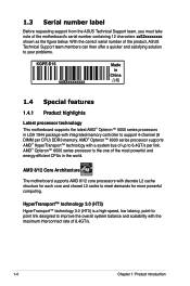
... DIMM per link. 1.3 Serial number label Before requesting support from the ASUS Technical Support team, you must take note of the most powerful and energy-efficient CPUs in LGA 1944 package with the maximum interconnect rate...powerful computing. AMD 8/12 Core Architecture The motherboard supports AMD 8/12 core processors with a system bus of 6.4GT/s. 1-4 Chapter 1: Product introduction AMD® Opteron™ 6000 series processor supports AMD® HyperTransport™ technology with discrete L2 cache structure for each core and shared L3 cache to your problems. KGPE-D16...
... DIMM per link. 1.3 Serial number label Before requesting support from the ASUS Technical Support team, you must take note of the most powerful and energy-efficient CPUs in LGA 1944 package with the maximum interconnect rate...powerful computing. AMD 8/12 Core Architecture The motherboard supports AMD 8/12 core processors with a system bus of 6.4GT/s. 1-4 Chapter 1: Product introduction AMD® Opteron™ 6000 series processor supports AMD® HyperTransport™ technology with discrete L2 cache structure for each core and shared L3 cache to your problems. KGPE-D16...
User Manual
Page 17
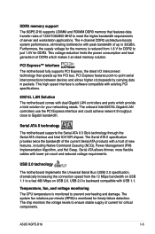
... levels to ensure stable supply of DDR3 which provide a total solution for timely failure detection. This voltage reduction limits the power consumption and heat generation of current for critical components. The onboard Intel 82574L Gigabit LAN controllers use the PCI Express interface and...The Serial ATA II specification provides twice the bandwidth of the current Serial ATA products with a host of up the PCI bus. ASUS KGPE-D16 1-5 The 4-channel DDR3 architecture boosts system performance, eliminating bottlenecks with dual Gigabit LAN controllers and ports which makes it an ideal ...
... levels to ensure stable supply of DDR3 which provide a total solution for timely failure detection. This voltage reduction limits the power consumption and heat generation of current for critical components. The onboard Intel 82574L Gigabit LAN controllers use the PCI Express interface and...The Serial ATA II specification provides twice the bandwidth of the current Serial ATA products with a host of up the PCI bus. ASUS KGPE-D16 1-5 The 4-channel DDR3 architecture boosts system performance, eliminating bottlenecks with dual Gigabit LAN controllers and ports which makes it an ideal ...

User Manual
Page 21
... strap or touch a safely grounded object or a metal object, such as the power supply case, before removing or plugging in soft-off or the power cord is detached from the power supply. 2.1 Before you proceed Take note of the onboard LED ASUS KGPE-D16 2-3 The green LED lights up to the motherboard, peripherals, and/or components...
... strap or touch a safely grounded object or a metal object, such as the power supply case, before removing or plugging in soft-off or the power cord is detached from the power supply. 2.1 Before you proceed Take note of the onboard LED ASUS KGPE-D16 2-3 The green LED lights up to the motherboard, peripherals, and/or components...

User Manual
Page 24
... EEB 1.1 compliant chassis. DO NOT overtighten the screws! To optimize the motherboard features, we highly recommend that you install it . Failure to unplug the chassis power cord before installing or removing the motherboard. Place this side towards the rear of the chassis 2-6 Chapter 2: Hardware information Doing so can cause you physical...
... EEB 1.1 compliant chassis. DO NOT overtighten the screws! To optimize the motherboard features, we highly recommend that you install it . Failure to unplug the chassis power cord before installing or removing the motherboard. Place this side towards the rear of the chassis 2-6 Chapter 2: Hardware information Doing so can cause you physical...

User Manual
Page 34
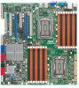
The figure illustrates the location of the DDR3 DIMM sockets: 2-16 Chapter 2: Hardware information A DDR3 module has the same physical dimensions as a DDR2 DIMM but is notched differently to prevent installation on a DDR2 DIMM socket. DDR3 modules are developed for better performance with sixteen (16) Double Data Rate 3 (DDR3) Dual Inline Memory Modules (DIMM) sockets. 2.4 System memory 2.4.1 Overview The motherboard comes with less power consumption.
The figure illustrates the location of the DDR3 DIMM sockets: 2-16 Chapter 2: Hardware information A DDR3 module has the same physical dimensions as a DDR2 DIMM but is notched differently to prevent installation on a DDR2 DIMM socket. DDR3 modules are developed for better performance with sixteen (16) Double Data Rate 3 (DDR3) Dual Inline Memory Modules (DIMM) sockets. 2.4 System memory 2.4.1 Overview The motherboard comes with less power consumption.

User Manual
Page 36
2.4.3 Installing a DIMM Unplug the power supply before adding or removing DIMMs or other system components. Align a DIMM on the socket such that it flips out with 1 1 your fingers when pressing ...
2.4.3 Installing a DIMM Unplug the power supply before adding or removing DIMMs or other system components. Align a DIMM on the socket such that it flips out with 1 1 your fingers when pressing ...

User Manual
Page 37
Failure to do not need to use . 4. Assign an IRQ to unplug the power cord before adding or removing expansion cards. Otherwise, conflicts will arise between the two PCI groups, making the system unstable and the card inoperable. ASUS KGPE-D16 2-19 Remove the system unit cover (if your motherboard is completely seated on the...
Failure to do not need to use . 4. Assign an IRQ to unplug the power cord before adding or removing expansion cards. Otherwise, conflicts will arise between the two PCI groups, making the system unstable and the card inoperable. ASUS KGPE-D16 2-19 Remove the system unit cover (if your motherboard is completely seated on the...

User Manual
Page 39
Install an optional ASUS PIKE RAID card based on cards. 2.5.6 PCI slot The PCI slot supports cards such as a LAN card, SCSI card, USB card, and other cards that comply with PCI specifications. 2.5.7 PIKE slot The PIKE slot allows you to complement the robust video power. 2.5.5 PCI Express x16 slots (x16 link; 2.5.4 MIO... supported) PCI-E x16 slot (Gen2 x16 link) PCI-E x8 slot (Gen2 x4 link) PCI-E x16 slot (Gen2 x16 link) (Auto switch to AMD SR5690 chipset. ASUS KGPE-D16 2-21 The MIO audio card offers great sound quality to choose and change your needs.
Install an optional ASUS PIKE RAID card based on cards. 2.5.6 PCI slot The PCI slot supports cards such as a LAN card, SCSI card, USB card, and other cards that comply with PCI specifications. 2.5.7 PIKE slot The PIKE slot allows you to complement the robust video power. 2.5.5 PCI Express x16 slots (x16 link; 2.5.4 MIO... supported) PCI-E x16 slot (Gen2 x16 link) PCI-E x8 slot (Gen2 x4 link) PCI-E x16 slot (Gen2 x16 link) (Auto switch to AMD SR5690 chipset. ASUS KGPE-D16 2-21 The MIO audio card offers great sound quality to choose and change your needs.

User Manual
Page 43
... Removing the cap will cause system boot failure! After the CMOS clearance, reinstall the battery. The onboard button cell battery powers the RAM data in CMOS. Plug the power cord and turn ON the computer. 4. You can clear the CMOS memory of date, time, and system setup parameters by...and move the cap back to pins 1- 2. 3. Turn OFF the computer and unplug the power cord. 2. Clear RTC RAM (CLRTC1) This jumper allows you to clear the CMOS RTC RAM data. 2.6 Jumpers 1. ASUS KGPE-D16 2-25 Keep the cap on CLRTC jumper default position. Except when clearing the RTC RAM, never...
... Removing the cap will cause system boot failure! After the CMOS clearance, reinstall the battery. The onboard button cell battery powers the RAM data in CMOS. Plug the power cord and turn ON the computer. 4. You can clear the CMOS memory of date, time, and system setup parameters by...and move the cap back to pins 1- 2. 3. Turn OFF the computer and unplug the power cord. 2. Clear RTC RAM (CLRTC1) This jumper allows you to clear the CMOS RTC RAM data. 2.6 Jumpers 1. ASUS KGPE-D16 2-25 Keep the cap on CLRTC jumper default position. Except when clearing the RTC RAM, never...

User Manual
Page 55
TPM connector (20-1 pin TPM) This connector supports a Trusted Platform Module (TPM) system, which can securely store keys, digital certificates, passwords, and data. A TPM system also helps enhance network security, protects digital identities, and ensures platform integrity. 12. ASUS KGPE-D16 2-37 Power Supply SMBus connector (5-pin PSUSMB1) This connector allows you to connect SMBus (System Management Bus) to the power supply unit to read PSU information. Devices communicate with an SMBus host and/or other SMBus devices using the SMBus interface. 11.
TPM connector (20-1 pin TPM) This connector supports a Trusted Platform Module (TPM) system, which can securely store keys, digital certificates, passwords, and data. A TPM system also helps enhance network security, protects digital identities, and ensures platform integrity. 12. ASUS KGPE-D16 2-37 Power Supply SMBus connector (5-pin PSUSMB1) This connector allows you to connect SMBus (System Management Bus) to the power supply unit to read PSU information. Devices communicate with an SMBus host and/or other SMBus devices using the SMBus interface. 11.

User Manual
Page 56
...8226; DO NOT forget to fit these connectors in only one orientation. otherwise, the system will not boot up if the power is recommended when configuring a system with more power-consuming devices. The system may become unstable or may not boot up . • Use of a PSU with a ...higher power output is inadequate. • Ensure that your power supply unit (PSU) can provide at least the minimum power required by your system. 2-38 Chapter 2: Hardware information 13. SSI power connectors (24-pin SSIPWR1, 8-pin SSI12V1, 8-pin SSI12V2) These ...
...8226; DO NOT forget to fit these connectors in only one orientation. otherwise, the system will not boot up if the power is recommended when configuring a system with more power-consuming devices. The system may become unstable or may not boot up . • Use of a PSU with a ...higher power output is inadequate. • Ensure that your power supply unit (PSU) can provide at least the minimum power required by your system. 2-38 Chapter 2: Hardware information 13. SSI power connectors (24-pin SSIPWR1, 8-pin SSI12V1, 8-pin SSI12V2) These ...

User Manual
Page 57
...speaker allows you turn on the system power, and blinks when the system is for the HDD Activity LED. Connect the chassis power LED cable to the front message LED. Pressing the power button turns the system on the BIOS settings. ASUS KGPE-D16 2-39 System power LED (3-pin PLED) This 3-pin... connector is in sleep or soft-off the system power. The system power LED lights up or flashes...
...speaker allows you turn on the system power, and blinks when the system is for the HDD Activity LED. Connect the chassis power LED cable to the front message LED. Pressing the power button turns the system on the BIOS settings. ASUS KGPE-D16 2-39 System power LED (3-pin PLED) This 3-pin... connector is in sleep or soft-off the system power. The system power LED lights up or flashes...

User Manual
Page 59
This chapter describes the power up Powerin3g up sequence, and ways of shutting down the system. Chapter 3:
This chapter describes the power up Powerin3g up sequence, and ways of shutting down the system. Chapter 3:

User Manual
Page 60
Chapter summary 3 3.1 Starting up for the first time 3-3 3.2 Powering off the computer 3-4 ASUS KGPE-D16
Chapter summary 3 3.1 Starting up for the first time 3-3 3.2 Powering off the computer 3-4 ASUS KGPE-D16

User Manual
Page 61
... down the key to the power connector at the back of the system chassis. 4. If your retailer for the first time 1. While the tests are off. 3. Check the jumper settings and connections or call your monitor complies with the last device on . ASUS KGPE-D16 3-3 If you do not... see anything within 30 seconds from the time you press the ATX power button. Connect the power cord to a power outlet that all the connections, replace the system case cover. 2. Monitor ...
... down the key to the power connector at the back of the system chassis. 4. If your retailer for the first time 1. While the tests are off. 3. Check the jumper settings and connections or call your monitor complies with the last device on . ASUS KGPE-D16 3-3 If you do not... see anything within 30 seconds from the time you press the ATX power button. Connect the power cord to a power outlet that all the connections, replace the system case cover. 2. Monitor ...


