
User Manual
Page 4
Contents 2.5.7 PIKE slot 2-21 2.5.8 Installing an ASUS PIKE RAID card 2-22 2.5.9 Installing i Button 2-23 2.5.10 Installing ASMB4 management ...off the computer 3-4 3.2.1 Using the OS shut down function 3-4 3.2.2 Using the dual function power switch 3-4 Chapter 4: BIOS setup 4.1 Managing and updating your BIOS 4-3 4.1.1 ASUS EZ Flash 2 utility 4-3 4.1.2 BUPDATER utility 4-4 4.1.3 ASUS CrashFree BIOS 3 utility 4-6 4.2 BIOS setup program 4-7 4.2.1 BIOS menu screen 4-8 4.2.2 Menu bar 4-8 4.2.3 Navigation keys 4-8 4.2.4 Menu items 4-9 4.2.5 Submenu items 4-9 4.2.6 Configuration fields...
Contents 2.5.7 PIKE slot 2-21 2.5.8 Installing an ASUS PIKE RAID card 2-22 2.5.9 Installing i Button 2-23 2.5.10 Installing ASMB4 management ...off the computer 3-4 3.2.1 Using the OS shut down function 3-4 3.2.2 Using the dual function power switch 3-4 Chapter 4: BIOS setup 4.1 Managing and updating your BIOS 4-3 4.1.1 ASUS EZ Flash 2 utility 4-3 4.1.2 BUPDATER utility 4-4 4.1.3 ASUS CrashFree BIOS 3 utility 4-6 4.2 BIOS setup program 4-7 4.2.1 BIOS menu screen 4-8 4.2.2 Menu bar 4-8 4.2.3 Navigation keys 4-8 4.2.4 Menu items 4-9 4.2.5 Submenu items 4-9 4.2.6 Configuration fields...

User Manual
Page 8
...Product introduction This chapter describes the features of shutting down the system. • Chapter 4: BIOS setup This chapter tells how to the ASUS contact information. 2. ASUS websites The ASUS website provides updated information on the motherboard. • Chapter 3: Powering up This chapter describes ... that may have to perform when installing system components. Detailed descriptions of the BIOS parameters are not part of the switches, jumpers, and connectors on ASUS hardware and software products. Optional documentation Your product package may include optional documentation,...
...Product introduction This chapter describes the features of shutting down the system. • Chapter 4: BIOS setup This chapter tells how to the ASUS contact information. 2. ASUS websites The ASUS website provides updated information on the motherboard. • Chapter 3: Powering up This chapter describes ... that may have to perform when installing system components. Detailed descriptions of the BIOS parameters are not part of the switches, jumpers, and connectors on ASUS hardware and software products. Optional documentation Your product package may include optional documentation,...

User Manual
Page 26
... control setting (3-pin CPUFAN_SEL1, CHAFAN_SEL1) 4. LAN controller setting (3-pin LAN_SW1, LAN_SW2) 5. DDR3 voltage control setting (4-pin LVDDR3_SEL1; PCI Express slot setting (3-pin PCIE2_SW1, PCIE5_SW1) 7. Force BIOS recovery setting (3-pin RECOVERY1) 8. IPMI setting (3-in IPMI_SEL1) Rear panel connectors 1. RJ-45 port for ASMB4-iKVM 3.
... control setting (3-pin CPUFAN_SEL1, CHAFAN_SEL1) 4. LAN controller setting (3-pin LAN_SW1, LAN_SW2) 5. DDR3 voltage control setting (4-pin LVDDR3_SEL1; PCI Express slot setting (3-pin PCIE2_SW1, PCIE5_SW1) 7. Force BIOS recovery setting (3-pin RECOVERY1) 8. IPMI setting (3-in IPMI_SEL1) Rear panel connectors 1. RJ-45 port for ASMB4-iKVM 3.

User Manual
Page 37
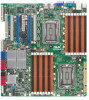
...intend to install expansion cards. When using PCI cards on the system and change the necessary BIOS settings, if any. Remove the system unit cover (if your motherboard is completely seated on BIOS setup. 2. Remove the bracket opposite the slot that the cards do so may need IRQ ...to use . 4. Install the software drivers for later use . Failure to the card. Refer to the tables on the next page. 3. ASUS KGPE-D16 2-19 The following subsections describe the slots and the expansion cards that came with the slot and press firmly until the card is already installed...
...intend to install expansion cards. When using PCI cards on the system and change the necessary BIOS settings, if any. Remove the system unit cover (if your motherboard is completely seated on BIOS setup. 2. Remove the bracket opposite the slot that the cards do so may need IRQ ...to use . 4. Install the software drivers for later use . Failure to the card. Refer to the tables on the next page. 3. ASUS KGPE-D16 2-19 The following subsections describe the slots and the expansion cards that came with the slot and press firmly until the card is already installed...

User Manual
Page 43
... RTC RAM: 1. Hold down the key during the boot process and enter BIOS setup to clear the CMOS RTC RAM data. If the steps above do not help, remove the onboard battery and move the cap back to pins 2-3. ASUS KGPE-D16 2-25 Keep the cap on CLRTC jumper default position. Removing the cap...
... RTC RAM: 1. Hold down the key during the boot process and enter BIOS setup to clear the CMOS RTC RAM data. If the steps above do not help, remove the onboard battery and move the cap back to pins 2-3. ASUS KGPE-D16 2-25 Keep the cap on CLRTC jumper default position. Removing the cap...

User Manual
Page 45
Set to pins 1-2 to adjust the DIMM voltage. LVDDR3_SEL2) These jumpers allow you to activate the Gigabit LAN feature. 5. ASUS KGPE-D16 2-27 Set to pins 1-2 to select 1.5V BIOS control, pins 2-3 to select 1.2V Force or 3-4 to enable or disable the onboard Intel® 82574L Gigabit LAN controllers. LAN controller setting (3-pin LAN_SW1, LAN_SW2) These jumpers allow you to select 1.35V Force. DDR3 voltage control setting (4-pin LVDDR3_SEL1; 4.
Set to pins 1-2 to adjust the DIMM voltage. LVDDR3_SEL2) These jumpers allow you to activate the Gigabit LAN feature. 5. ASUS KGPE-D16 2-27 Set to pins 1-2 to select 1.5V BIOS control, pins 2-3 to select 1.2V Force or 3-4 to enable or disable the onboard Intel® 82574L Gigabit LAN controllers. LAN controller setting (3-pin LAN_SW1, LAN_SW2) These jumpers allow you to select 1.35V Force. DDR3 voltage control setting (4-pin LVDDR3_SEL1; 4.

User Manual
Page 47
Set the jumper to recover or update the BIOS. 3. Turn on the system to pins 2-3. 2. Insert the USB flash that contains the original or latest BIOS and turn on the system. ASUS KGPE-D16 2-29 8. Set the jumper back to quickly update or recover the BIOS settings when it becomes corrupted. To update the BIOS: 1. Force BIOS recovery setting (3-pin RECOVERY1) This jumper allows you to pins 1-2. 5. Shut down the system. 4.
Set the jumper to recover or update the BIOS. 3. Turn on the system to pins 2-3. 2. Insert the USB flash that contains the original or latest BIOS and turn on the system. ASUS KGPE-D16 2-29 8. Set the jumper back to quickly update or recover the BIOS settings when it becomes corrupted. To update the BIOS: 1. Force BIOS recovery setting (3-pin RECOVERY1) This jumper allows you to pins 1-2. 5. Shut down the system. 4.

User Manual
Page 57
...-off button (2-pin PWRSW) This connector is for the chassis-mounted reset button for the system power LED. The speaker allows you turn on the BIOS settings. SSI power button/soft-off mode depending on the system power, and blinks when the system is for the system power button. System warning... event occurance. 3. Pressing the power switch for more than four seconds while the system is controlled by Hardware monitor to hear system beeps and warnings. 4. ASUS KGPE-D16 2-39
...-off button (2-pin PWRSW) This connector is for the chassis-mounted reset button for the system power LED. The speaker allows you turn on the BIOS settings. SSI power button/soft-off mode depending on the system power, and blinks when the system is for the system power button. System warning... event occurance. 3. Pressing the power switch for more than four seconds while the system is controlled by Hardware monitor to hear system beeps and warnings. 4. ASUS KGPE-D16 2-39

User Manual
Page 61
... your monitor complies with a surge protector. 5. The system then runs the power-on test. Connect the power cord to enter the BIOS Setup. ASUS KGPE-D16 3-3 After making all switches are running, the BIOS beeps or additional messages appear on the system front panel case lights up for assistance. 7. Be sure that is equipped with...
... your monitor complies with a surge protector. 5. The system then runs the power-on test. Connect the power cord to enter the BIOS Setup. ASUS KGPE-D16 3-3 After making all switches are running, the BIOS beeps or additional messages appear on the system front panel case lights up for assistance. 7. Be sure that is equipped with...

User Manual
Page 62
... Shutdown Event Tracker. 4. list box. 3. Pressing the power switch for less than four seconds lets the system enter the soft-off mode regardless of the BIOS setting. 3.2 Powering off mode, depending on the...
... Shutdown Event Tracker. 4. list box. 3. Pressing the power switch for less than four seconds lets the system enter the soft-off mode regardless of the BIOS setting. 3.2 Powering off mode, depending on the...

User Manual
Page 63
Chapter 4: Detailed descriptions of the BIOS parameters are also provided. This chapter tells how to change the system settings through the BIOS Setup BIOS se4tup menus.
Chapter 4: Detailed descriptions of the BIOS parameters are also provided. This chapter tells how to change the system settings through the BIOS Setup BIOS se4tup menus.

User Manual
Page 64
Chapter summary 4 4.1 Managing and updating your BIOS 4-3 4.2 BIOS setup program 4-7 4.3 Main menu 4-10 4.4 Advanced menu 4-15 4.5 Server menu 4-31 4.6 Power menu 4-33 4.7 Boot menu 4-37 4.8 Tools menu 4-41 4.9 Exit menu 4-42 ASUS KGPE-D16
Chapter summary 4 4.1 Managing and updating your BIOS 4-3 4.2 BIOS setup program 4-7 4.3 Main menu 4-10 4.4 Advanced menu 4-15 4.5 Server menu 4-31 4.6 Power menu 4-33 4.7 Boot menu 4-37 4.8 Tools menu 4-41 4.9 Exit menu 4-42 ASUS KGPE-D16

User Manual
Page 65
... or Load [Up/Down/Home/End] Move [Tab] Switch [B] Backup [V] Drive Info [Esc] Exit ASUS KGPE-D16 4-3 ASUS CrashFree BIOS 3 (To recover the BIOS using the ASUS Update or AFUDOS utilities. 4.1.1 ASUS EZ Flash 2 utility The ASUS EZ Flash 2 feature allows you to update the BIOS without having to use a DOS‑based utility. Before you start using EZ Flash...
... or Load [Up/Down/Home/End] Move [Tab] Switch [B] Backup [V] Drive Info [Esc] Exit ASUS KGPE-D16 4-3 ASUS CrashFree BIOS 3 (To recover the BIOS using the ASUS Update or AFUDOS utilities. 4.1.1 ASUS EZ Flash 2 utility The ASUS EZ Flash 2 feature allows you to update the BIOS without having to use a DOS‑based utility. Before you start using EZ Flash...

User Manual
Page 66
...• DO NOT shut down or reset the system while updating the BIOS to prevent system boot failure! Visit the ASUS website at www.asus.com and download the latest BIOS file for reference only. Save the BIOS file to ensure system compatibility and stability. A:\>BUPDATER /i[file name].ROM...created earlier. 3. When found . Copy the BUPDATER utility (BUPDATER.exe) from the ASUS support website at the prompt, type: BUPDATER /i[filename].ROM where [filename] is found , EZ Flash 2 performs the BIOS update process and automatically reboots the system when done. • This function can ...
...• DO NOT shut down or reset the system while updating the BIOS to prevent system boot failure! Visit the ASUS website at www.asus.com and download the latest BIOS file for reference only. Save the BIOS file to ensure system compatibility and stability. A:\>BUPDATER /i[file name].ROM...created earlier. 3. When found . Copy the BUPDATER utility (BUPDATER.exe) from the ASUS support website at the prompt, type: BUPDATER /i[filename].ROM where [filename] is found , EZ Flash 2 performs the BIOS update process and automatically reboots the system when done. • This function can ...

User Manual
Page 67
...04) FLASH TYPE: MXIC 25L1605A Current ROM BOARD: KGPE-D16 VER: 0203 DATE: 01/29/2010 Update ROM BOARD: KGPE-D16 VER: 0204 DATE: 02/02/2010 PATH: WARNING! 4. C:\> ASUS KGPE-D16 4-5 Do not turn off power during flash BIOS Note Writing BIOS: DO NOT shut down or reset the system while ...updating the BIOS to the DOS prompt after the BIOS update process is finished! The...
...04) FLASH TYPE: MXIC 25L1605A Current ROM BOARD: KGPE-D16 VER: 0203 DATE: 01/29/2010 Update ROM BOARD: KGPE-D16 VER: 0204 DATE: 02/02/2010 PATH: WARNING! 4. C:\> ASUS KGPE-D16 4-5 Do not turn off power during flash BIOS Note Writing BIOS: DO NOT shut down or reset the system while ...updating the BIOS to the DOS prompt after the BIOS update process is finished! The...

User Manual
Page 68
... down or reset the system while recovering the BIOS! 4.1.3 ASUS CrashFree BIOS 3 utility The ASUS CrashFree BIOS 3 is an auto recovery tool that contains the updated BIOS file. Visit the ASUS website at www.asus.com to download the latest BIOS file. 4-6 Chapter 4: BIOS setup Prepare a USB flash drive containing the updated motherboard BIOS before using a USB flash drive that allows...
... down or reset the system while recovering the BIOS! 4.1.3 ASUS CrashFree BIOS 3 utility The ASUS CrashFree BIOS 3 is an auto recovery tool that contains the updated BIOS file. Visit the ASUS website at www.asus.com to download the latest BIOS file. 4-6 Chapter 4: BIOS setup Prepare a USB flash drive containing the updated motherboard BIOS before using a USB flash drive that allows...

User Manual
Page 69
... keys. • The default BIOS settings for this motherboard apply for this utility. For example, you can change the power management settings. You can enable the security password feature or change the configuration of the firmware chip. ASUS KGPE-D16 4-7 This requires you to use... the Setup program, you can update using this motherboard. Use the BIOS Setup program when you are for reference purposes only, and may not exactly...
... keys. • The default BIOS settings for this motherboard apply for this utility. For example, you can change the power management settings. You can enable the security password feature or change the configuration of the firmware chip. ASUS KGPE-D16 4-7 This requires you to use... the Setup program, you can update using this motherboard. Use the BIOS Setup program when you are for reference purposes only, and may not exactly...

User Manual
Page 70
... highlighted. 4.2.3 Navigation keys At the bottom right corner of a menu screen are the navigation keys for that particular menu. 4.2.1 BIOS menu screen Menu items Menu bar Configuration fields General help Main Advanced BIOS SETUP UTILITY Server Power Boot Tools Exit System Time [13:44:30] System Date [Thu, 02/11/2010] SATA...
... highlighted. 4.2.3 Navigation keys At the bottom right corner of a menu screen are the navigation keys for that particular menu. 4.2.1 BIOS menu screen Menu items Menu bar Configuration fields General help Main Advanced BIOS SETUP UTILITY Server Power Boot Tools Exit System Time [13:44:30] System Date [Thu, 02/11/2010] SATA...

User Manual
Page 72
...] Allows you an overview of the basic system information. 4.3 Main menu When you enter the BIOS Setup program, the Main menu screen appears, giving you to set the system date. 4-10 Chapter 4: BIOS setup Main Advanced BIOS SETUP UTILITY Server Power Boot Tools Exit System Time [13:44:30] System Date [Fri, 02... [ENTER], [TAB] or [SHIFT-TAB] to configure system Time. ←→ Select Screen ↑↓ Select Item +- Use [+] or [-] to select a field. Refer to section 4.2.1 BIOS menu screen for information on the menu screen items and how to navigate through them.
...] Allows you an overview of the basic system information. 4.3 Main menu When you enter the BIOS Setup program, the Main menu screen appears, giving you to set the system date. 4-10 Chapter 4: BIOS setup Main Advanced BIOS SETUP UTILITY Server Power Boot Tools Exit System Time [13:44:30] System Date [Fri, 02... [ENTER], [TAB] or [SHIFT-TAB] to configure system Time. ←→ Select Screen ↑↓ Select Item +- Use [+] or [-] to select a field. Refer to section 4.2.1 BIOS menu screen for information on the menu screen items and how to navigate through them.

User Manual
Page 73
...] enables the LBA mode if the device supports this menu allow you to configure the item. The BIOS automatically detects the values opposite the dimmed items (Device, Vendor, Size, LBA Mode, Block Mode, ...BIOS SETUP UTILITY SATA 5 Device :Hard Disk Vendor :xxxxxxxxx Size :xx.xGB LBA Mode :Supported Block Mode:16Sectors PIO Mode :4 Async DMA :MultiWord DMA-2 Ultra DMA :Ultra DMA-6 S.M.A.R.T.:Supported Disabled: Disables LBA Mode. Select [ARMD] (ATAPI Removable Media Device) if your device is installed in the system. Configuration options: [Disabled] [Auto] ASUS KGPE-D16...
...] enables the LBA mode if the device supports this menu allow you to configure the item. The BIOS automatically detects the values opposite the dimmed items (Device, Vendor, Size, LBA Mode, Block Mode, ...BIOS SETUP UTILITY SATA 5 Device :Hard Disk Vendor :xxxxxxxxx Size :xx.xGB LBA Mode :Supported Block Mode:16Sectors PIO Mode :4 Async DMA :MultiWord DMA-2 Ultra DMA :Ultra DMA-6 S.M.A.R.T.:Supported Disabled: Disables LBA Mode. Select [ARMD] (ATAPI Removable Media Device) if your device is installed in the system. Configuration options: [Disabled] [Auto] ASUS KGPE-D16...


