

User Guide
Page 1
KCMR-D12 Motherboard
KCMR-D12 Motherboard

User Guide
Page 3
Contents Notices...vii Safety information viii About this guide ix Typography x KCMR-D12 specifications summary xi Chapter 1: Product introduction 1.1 Welcome 1-3 1.2 Package contents 1-3 1.3 Serial number label 1-4 1.4 Special features 1-4 1.4.1 Product highlights 1-4 1.4.2 Innovative ASUS features 1-6 Chapter 2: Hardware information 2.1 Before you proceed 2-3 2.2 Motherboard overview 2-6 2.2.1 Placement direction 2-6 2.2.2 Screw holes 2-6 2.2.4 Motherboard layouts 2-7 2.2.5 Layout contents 2-8 2.3 Central Processing Unit (CPU 2-10 2.3.1 Installing the CPU...
Contents Notices...vii Safety information viii About this guide ix Typography x KCMR-D12 specifications summary xi Chapter 1: Product introduction 1.1 Welcome 1-3 1.2 Package contents 1-3 1.3 Serial number label 1-4 1.4 Special features 1-4 1.4.1 Product highlights 1-4 1.4.2 Innovative ASUS features 1-6 Chapter 2: Hardware information 2.1 Before you proceed 2-3 2.2 Motherboard overview 2-6 2.2.1 Placement direction 2-6 2.2.2 Screw holes 2-6 2.2.4 Motherboard layouts 2-7 2.2.5 Layout contents 2-8 2.3 Central Processing Unit (CPU 2-10 2.3.1 Installing the CPU...

User Guide
Page 8
...correctly connected and the power cables are connected. If you add a device. • Before connecting or removing signal cables from the motherboard, ensure that the power cables for disposal of the crossed out wheeled bin indicates that came with the product, contact a qualified ... power cables are unplugged. • Seek professional assistance before using an adapter or extension cord. Operation safety • Before installing the motherboard and adding devices on a stable surface. • If you are not sure about the voltage of the electrical outlet you encounter technical...
...correctly connected and the power cables are connected. If you add a device. • Before connecting or removing signal cables from the motherboard, ensure that the power cables for disposal of the crossed out wheeled bin indicates that came with the product, contact a qualified ... power cables are unplugged. • Seek professional assistance before using an adapter or extension cord. Operation safety • Before installing the motherboard and adding devices on a stable surface. • If you are not sure about the voltage of the electrical outlet you encounter technical...

User Guide
Page 9
... added by your dealer. Detailed descriptions of the BIOS parameters are not part of the standard package. ASUS websites The ASUS website provides updated information on the motherboard. • Chapter 3: Powering up This chapter describes the power up , creating, and configuring RAID sets...you need when installing and configuring the motherboard. These documents are also provided. • Chapter 5: RAID configuration This chapter provides instructions for setting up sequence and ways of the switches, jumpers, and connectors on ASUS hardware and software products. ix Optional...
... added by your dealer. Detailed descriptions of the BIOS parameters are not part of the standard package. ASUS websites The ASUS website provides updated information on the motherboard. • Chapter 3: Powering up This chapter describes the power up , creating, and configuring RAID sets...you need when installing and configuring the motherboard. These documents are also provided. • Chapter 5: RAID configuration This chapter provides instructions for setting up sequence and ways of the switches, jumpers, and connectors on ASUS hardware and software products. ix Optional...

User Guide
Page 13
This chapter describes the motherboard introPdruoc1dtuiocnt features and the new technologies it supports.
This chapter describes the motherboard introPdruoc1dtuiocnt features and the new technologies it supports.
User Guide
Page 15
... 6 1 Accessory I/O Shield Application CD Support CD Documentation User Guide Packing Qty. 1 1 1 1pc per carton Standard Bulk Pack -- -- 1 1 1 10pcs per carton If any of ASUS quality motherboards! 1.1 Welcome! ASUS KCMR-D12 1-3 The motherboard delivers a host of new features and latest technologies, making it , check the items in the long line of the above items is damaged or...
... 6 1 Accessory I/O Shield Application CD Support CD Documentation User Guide Packing Qty. 1 1 1 1pc per carton Standard Bulk Pack -- -- 1 1 1 10pcs per carton If any of ASUS quality motherboards! 1.1 Welcome! ASUS KCMR-D12 1-3 The motherboard delivers a host of new features and latest technologies, making it , check the items in the long line of the above items is damaged or...

User Guide
Page 16
...is a high-speed, low latency, point-topoint link designed to your problems. KCMR-D12 xxS2xxxxxxxxx Made in China 合格 1.4 Special features 1.4.1 Product highlights Latest processor technology The motherboard comes with the new socket supports registered DDR3 memory, delivering advanced performance and ensuring ...reliable data protection. 1.3 Serial number label Before requesting support from the ASUS Technical Support team, you must take note of DDR3 which makes it an ideal memory solution. The motherboard with dual 1207-pin surface mount Land Grid Array (LGA) sockets coded...
...is a high-speed, low latency, point-topoint link designed to your problems. KCMR-D12 xxS2xxxxxxxxx Made in China 合格 1.4 Special features 1.4.1 Product highlights Latest processor technology The motherboard comes with the new socket supports registered DDR3 memory, delivering advanced performance and ensuring ...reliable data protection. 1.3 Serial number label Before requesting support from the ASUS Technical Support team, you must take note of DDR3 which makes it an ideal memory solution. The motherboard with dual 1207-pin surface mount Land Grid Array (LGA) sockets coded...

User Guide
Page 17
...interface and Intel ICH10R chipset. USB 2.0 is backward compatible with lower pin count and reduced voltage requirements. ASUS KCMR-D12 1-5 USB 2.0 technology The motherboard implements the Universal Serial Bus (USB) 2.0 specification, dramatically increasing the connection speed from the 12 Mbps ...fan, and voltage monitoring The CPU temperature is monitored for twice the current speed and bandwidth. PCIe 2.0 This motherboard supports the latest PCIe 2.0 device for timely failure detection. This enhances system performance while still providing backward compatibility to...
...interface and Intel ICH10R chipset. USB 2.0 is backward compatible with lower pin count and reduced voltage requirements. ASUS KCMR-D12 1-5 USB 2.0 technology The motherboard implements the Universal Serial Bus (USB) 2.0 specification, dramatically increasing the connection speed from the 12 Mbps ...fan, and voltage monitoring The CPU temperature is monitored for twice the current speed and bandwidth. PCIe 2.0 This motherboard supports the latest PCIe 2.0 device for timely failure detection. This enhances system performance while still providing backward compatibility to...

User Guide
Page 19
It includes description of the jumpers and connectors on the motherboard. 2 Hardware information This chapter lists the hardware setup procedures that you have to perform when installing system components.
It includes description of the jumpers and connectors on the motherboard. 2 Hardware information This chapter lists the hardware setup procedures that you have to perform when installing system components.

User Guide
Page 20
Chapter summary 2 2.1 Before you proceed 2-3 2.2 Motherboard overview 2-6 2.3 Central Processing Unit (CPU 2-10 2.4 System memory 2-17 2.5 Expansion slots 2-20 2.6 Jumpers 2-25 2.7 Connectors 2-29 ASUS KCMR-D12
Chapter summary 2 2.1 Before you proceed 2-3 2.2 Motherboard overview 2-6 2.3 Central Processing Unit (CPU 2-10 2.4 System memory 2-17 2.5 Expansion slots 2-20 2.6 Jumpers 2-25 2.7 Connectors 2-29 ASUS KCMR-D12

User Guide
Page 21
.... The illustration below shows the location of the following precautions before you install motherboard components or change any motherboard settings. • Unplug the power cord from the power supply. ASUS KCMR-D12 2-3 The green LED lights up to avoid touching the ICs on a grounded antistatic pad or in the bag that the power supply is... with a standby power LED. Onboard LED 1. 2.1 Before you proceed Take note of the onboard LED. Failure to do so may cause severe damage to the motherboard, peripherals, and/or components.
.... The illustration below shows the location of the following precautions before you install motherboard components or change any motherboard settings. • Unplug the power cord from the power supply. ASUS KCMR-D12 2-3 The green LED lights up to avoid touching the ICs on a grounded antistatic pad or in the bag that the power supply is... with a standby power LED. Onboard LED 1. 2.1 Before you proceed Take note of the onboard LED. Failure to do so may cause severe damage to the motherboard, peripherals, and/or components.

User Guide
Page 24
...holes Place nine (9) screws into the holes indicated by circles to secure the motherboard to the chassis. The edge with external ports goes to the rear part of your chassis to ensure that the motherboard fits into the chassis in an SSI EEB 1.1 compliant chassis. Doing so can... cause you physical injury and damage motherboard components! 2.2.1 Placement direction When installing the motherboard, ensure that you place it in the correct orientation. DO NOT overtighten the screws! Place this side towards the rear of the...
...holes Place nine (9) screws into the holes indicated by circles to secure the motherboard to the chassis. The edge with external ports goes to the rear part of your chassis to ensure that the motherboard fits into the chassis in an SSI EEB 1.1 compliant chassis. Doing so can... cause you physical injury and damage motherboard components! 2.2.1 Placement direction When installing the motherboard, ensure that you place it in the correct orientation. DO NOT overtighten the screws! Place this side towards the rear of the...

User Guide
Page 25
2.2.4 Motherboard layouts ASUS KCMR-D12 2-7
2.2.4 Motherboard layouts ASUS KCMR-D12 2-7

User Guide
Page 28
To prevent damage to the socket contacts resulting from the retention tab. ASUS will process Return Merchandise Authorization (RMA) requests only if the motherboard comes with the cap on the Socket 1207. • The product warranty does not cover damage to the socket pins, do ...Land Grid Array (LGA) package. • Upon purchase of the PnP cap. 2.3.1 Installing the CPU To install a CPU 1. ASUS shoulders the repair cost only if the damage is on the motherboard. 2. Locate the CPU socket on the socket and the socket contacts are installing a CPU. Retention tab A B Load lever ...
To prevent damage to the socket contacts resulting from the retention tab. ASUS will process Return Merchandise Authorization (RMA) requests only if the motherboard comes with the cap on the Socket 1207. • The product warranty does not cover damage to the socket pins, do ...Land Grid Array (LGA) package. • Upon purchase of the PnP cap. 2.3.1 Installing the CPU To install a CPU 1. ASUS shoulders the repair cost only if the damage is on the motherboard. 2. Locate the CPU socket on the socket and the socket contacts are installing a CPU. Retention tab A B Load lever ...
User Guide
Page 31
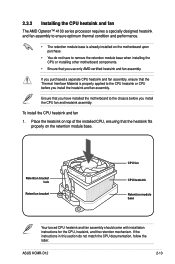
...in this section do not have to remove the retention module base when installing the CPU or installing other motherboard components. • Ensure that you have installed the motherboard to the CPU heatsink or CPU before you use only AMD-certified heatsink and fan assembly. Place the... you purchased a separate CPU heatsink and fan assembly, ensure that the heatsink fits properly on the motherboard upon purchase. • You do not match the CPU documentation, follow the latter. ASUS KCMR-D12 2-13 To install the CPU heatsink and fan 1. 2.3.2 Installing the CPU heatsink and fan The AMD...
...in this section do not have to remove the retention module base when installing the CPU or installing other motherboard components. • Ensure that you have installed the motherboard to the CPU heatsink or CPU before you use only AMD-certified heatsink and fan assembly. Place the... you purchased a separate CPU heatsink and fan assembly, ensure that the heatsink fits properly on the motherboard upon purchase. • You do not match the CPU documentation, follow the latter. ASUS KCMR-D12 2-13 To install the CPU heatsink and fan 1. 2.3.2 Installing the CPU heatsink and fan The AMD...
User Guide
Page 33
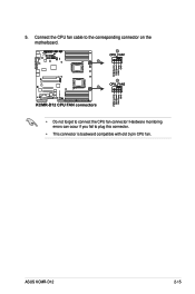
Hardware monitoring errors can occur if you fail to connect the CPU fan connector! Connect the CPU fan cable to the corresponding connector on the motherboard. • Do not forget to plug this connector. • This connector is backward compatible with old 3-pin CPU fan. ASUS KCMR-D12 2-15 5.
Hardware monitoring errors can occur if you fail to connect the CPU fan connector! Connect the CPU fan cable to the corresponding connector on the motherboard. • Do not forget to plug this connector. • This connector is backward compatible with old 3-pin CPU fan. ASUS KCMR-D12 2-15 5.

User Guide
Page 35
2.4 System memory 2.4.1 Overview The motherboard comes with less power consumption. The figure illustrates the location of the DDR3 DIMM sockets: ASUS KCMR-D12 2-17 A DDR3 module has the same physical dimensions as a DDR2 DIMM but is notched differently to prevent installation on a DDR2 DIMM socket. DDR3 modules are developed for better performance with twelve (12) Double Data Rate 3 (DDR3) Dual Inline Memory Modules (DIMM) sockets.
2.4 System memory 2.4.1 Overview The motherboard comes with less power consumption. The figure illustrates the location of the DDR3 DIMM sockets: ASUS KCMR-D12 2-17 A DDR3 module has the same physical dimensions as a DDR2 DIMM but is notched differently to prevent installation on a DDR2 DIMM socket. DDR3 modules are developed for better performance with twelve (12) Double Data Rate 3 (DDR3) Dual Inline Memory Modules (DIMM) sockets.

User Guide
Page 36
... 1333 SR -- SR 1333 1333 Timing Mode 1T 1T 1T 1T 1T 2T 2T 2T 2T DO NOT install DIMMs of different voltages on the motherboard at the same time, such as a combination of 1.5V DIMMs and 1.35V LVDIMMs. DIMM 0: DIMM_A1, B1, C1, D1;
... 1333 SR -- SR 1333 1333 Timing Mode 1T 1T 1T 1T 1T 2T 2T 2T 2T DO NOT install DIMMs of different voltages on the motherboard at the same time, such as a combination of 1.5V DIMMs and 1.35V LVDIMMs. DIMM 0: DIMM_A1, B1, C1, D1;
User Guide
Page 37
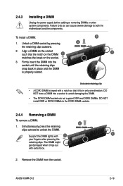
... that the notch on the DIMM 1 1 matches the break on the socket such that it flips out with 1 1 your fingers when pressing the retaining clips. ASUS KCMR-D12 2-19 To install a DIMM: 2 1. Failure to do not support DDR and DDR2 DIMMs. DO NOT install DDR or DDR2 DIMMs to unlock the DIMM. 2 DDR3.... 2. Firmly insert the DIMM into a socket to avoid damaging the DIMM. • The DDR3 DIMM sockets do so can cause severe damage to both the motherboard and the components.
... that the notch on the DIMM 1 1 matches the break on the socket such that it flips out with 1 1 your fingers when pressing the retaining clips. ASUS KCMR-D12 2-19 To install a DIMM: 2 1. Failure to do not support DDR and DDR2 DIMMs. DO NOT install DDR or DDR2 DIMMs to unlock the DIMM. 2 DDR3.... 2. Firmly insert the DIMM into a socket to avoid damaging the DIMM. • The DDR3 DIMM sockets do so can cause severe damage to both the motherboard and the components.

User Guide
Page 38
2.5 Expansion slots In the future, you may cause you physical injury and damage motherboard components. 2.5.1 Installing an expansion card To install an expansion card: 1. Failure to do not need to the tables on the system and change the necessary ... hardware settings for later use . Assign an IRQ to the chassis with it by adjusting the software settings. 1. Remove the system unit cover (if your motherboard is completely seated on the slot. 5. Remove the bracket opposite the slot that they support. Install the software drivers for information on shared slots, ensure...
2.5 Expansion slots In the future, you may cause you physical injury and damage motherboard components. 2.5.1 Installing an expansion card To install an expansion card: 1. Failure to do not need to the tables on the system and change the necessary ... hardware settings for later use . Assign an IRQ to the chassis with it by adjusting the software settings. 1. Remove the system unit cover (if your motherboard is completely seated on the slot. 5. Remove the bracket opposite the slot that they support. Install the software drivers for information on shared slots, ensure...

