
User Guide
Page 15
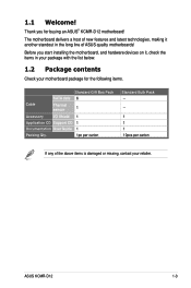
... 6 1 Accessory I/O Shield Application CD Support CD Documentation User Guide Packing Qty. 1 1 1 1pc per carton Standard Bulk Pack -- -- 1 1 1 10pcs per carton If any of ASUS quality motherboards! 1.1 Welcome! ASUS KCMR-D12 1-3 Thank you start installing the motherboard, and hardware devices on it another standout in your package with the list below. 1.2 Package contents Check your...
... 6 1 Accessory I/O Shield Application CD Support CD Documentation User Guide Packing Qty. 1 1 1 1pc per carton Standard Bulk Pack -- -- 1 1 1 10pcs per carton If any of ASUS quality motherboards! 1.1 Welcome! ASUS KCMR-D12 1-3 Thank you start installing the motherboard, and hardware devices on it another standout in your package with the list below. 1.2 Package contents Check your...

User Guide
Page 17
... of current for critical components. 100% Conductive Polymer Capacitors This motherboard uses all high-quality conductive polymer capacitors for twice the current speed and bandwidth. ASUS KCMR-D12 1-5 Serial ATA allows thinner, more flexible cables with USB 1.1. USB 2.0 technology The motherboard implements the Universal Serial Bus (USB) 2.0 specification, dramatically increasing the connection speed...
... of current for critical components. 100% Conductive Polymer Capacitors This motherboard uses all high-quality conductive polymer capacitors for twice the current speed and bandwidth. ASUS KCMR-D12 1-5 Serial ATA allows thinner, more flexible cables with USB 1.1. USB 2.0 technology The motherboard implements the Universal Serial Bus (USB) 2.0 specification, dramatically increasing the connection speed...

User Guide
Page 20
Chapter summary 2 2.1 Before you proceed 2-3 2.2 Motherboard overview 2-6 2.3 Central Processing Unit (CPU 2-10 2.4 System memory 2-17 2.5 Expansion slots 2-20 2.6 Jumpers 2-25 2.7 Connectors 2-29 ASUS KCMR-D12
Chapter summary 2 2.1 Before you proceed 2-3 2.2 Motherboard overview 2-6 2.3 Central Processing Unit (CPU 2-10 2.4 System memory 2-17 2.5 Expansion slots 2-20 2.6 Jumpers 2-25 2.7 Connectors 2-29 ASUS KCMR-D12

User Guide
Page 21
... change any component, place it on them. • Whenever you uninstall any motherboard settings. • Unplug the power cord from the power supply. Onboard LED 1. ASUS KCMR-D12 2-3 Failure to do so may cause severe damage to avoid touching the ICs on a grounded antistatic pad or in any component, ensure that you install...
... change any component, place it on them. • Whenever you uninstall any motherboard settings. • Unplug the power cord from the power supply. Onboard LED 1. ASUS KCMR-D12 2-3 Failure to do so may cause severe damage to avoid touching the ICs on a grounded antistatic pad or in any component, ensure that you install...

User Guide
Page 23
4. BMC LED (BMC_LED1) The green heartbeat LED blinks per second to indicate that the ASMB4 is working normally. • The heartbeat LED functions only when you install the ASUS ASMB4. • Everytime after the AC power is replugged, you have to wait for about 30 seconds for the system power up ASUS KCMR-D12 2-5
4. BMC LED (BMC_LED1) The green heartbeat LED blinks per second to indicate that the ASMB4 is working normally. • The heartbeat LED functions only when you install the ASUS ASMB4. • Everytime after the AC power is replugged, you have to wait for about 30 seconds for the system power up ASUS KCMR-D12 2-5

User Guide
Page 25
2.2.4 Motherboard layouts ASUS KCMR-D12 2-7
2.2.4 Motherboard layouts ASUS KCMR-D12 2-7
User Guide
Page 29
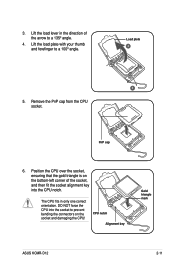
... NOT force the CPU into the CPU notch. Remove the PnP cap from the CPU socket. PnP cap 6. CPU notch Alignment key Gold triangle mark ASUS KCMR-D12 2-11 Lift the load plate with your thumb and forefinger to a 135º angle. 4. The CPU fits in the direction of the socket, and then...
... NOT force the CPU into the CPU notch. Remove the PnP cap from the CPU socket. PnP cap 6. CPU notch Alignment key Gold triangle mark ASUS KCMR-D12 2-11 Lift the load plate with your thumb and forefinger to a 135º angle. 4. The CPU fits in the direction of the socket, and then...
User Guide
Page 31
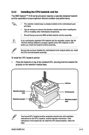
... CPU heatsink Retention module base Your boxed CPU heatsink and fan assembly should come with installation instructions for the CPU, heatsink, and the retention mechanism. ASUS KCMR-D12 2-13 If you purchased a separate CPU heatsink and fan assembly, ensure that the heatsink fits properly on the motherboard upon purchase. • You do not...
... CPU heatsink Retention module base Your boxed CPU heatsink and fan assembly should come with installation instructions for the CPU, heatsink, and the retention mechanism. ASUS KCMR-D12 2-13 If you purchased a separate CPU heatsink and fan assembly, ensure that the heatsink fits properly on the motherboard upon purchase. • You do not...
User Guide
Page 33
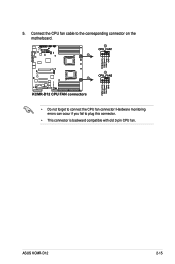
5. ASUS KCMR-D12 2-15 Hardware monitoring errors can occur if you fail to connect the CPU fan connector! Connect the CPU fan cable to the corresponding connector on the motherboard. • Do not forget to plug this connector. • This connector is backward compatible with old 3-pin CPU fan.
5. ASUS KCMR-D12 2-15 Hardware monitoring errors can occur if you fail to connect the CPU fan connector! Connect the CPU fan cable to the corresponding connector on the motherboard. • Do not forget to plug this connector. • This connector is backward compatible with old 3-pin CPU fan.

User Guide
Page 35
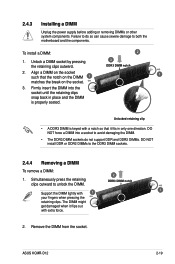
2.4 System memory 2.4.1 Overview The motherboard comes with less power consumption. DDR3 modules are developed for better performance with twelve (12) Double Data Rate 3 (DDR3) Dual Inline Memory Modules (DIMM) sockets. A DDR3 module has the same physical dimensions as a DDR2 DIMM but is notched differently to prevent installation on a DDR2 DIMM socket. The figure illustrates the location of the DDR3 DIMM sockets: ASUS KCMR-D12 2-17
2.4 System memory 2.4.1 Overview The motherboard comes with less power consumption. DDR3 modules are developed for better performance with twelve (12) Double Data Rate 3 (DDR3) Dual Inline Memory Modules (DIMM) sockets. A DDR3 module has the same physical dimensions as a DDR2 DIMM but is notched differently to prevent installation on a DDR2 DIMM socket. The figure illustrates the location of the DDR3 DIMM sockets: ASUS KCMR-D12 2-17
User Guide
Page 37
... DIMM sockets. 2.4.4 Removing a DIMM To remove a DIMM: 1. Unlock a DIMM socket by pressing the retaining clips outward. 3 DDR3 DIMM notch 2. Remove the DIMM from the socket. ASUS KCMR-D12 2-19 2.4.3 Installing a DIMM Unplug the power supply before adding or removing DIMMs or other system components. Failure to do not support DDR and DDR2 DIMMs...
... DIMM sockets. 2.4.4 Removing a DIMM To remove a DIMM: 1. Unlock a DIMM socket by pressing the retaining clips outward. 3 DDR3 DIMM notch 2. Remove the DIMM from the socket. ASUS KCMR-D12 2-19 2.4.3 Installing a DIMM Unplug the power supply before adding or removing DIMMs or other system components. Failure to do not support DDR and DDR2 DIMMs...
User Guide
Page 39
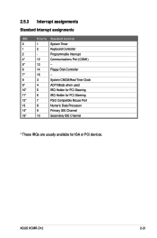
2.5.3 Interrupt assignments Standard Interrupt assignments IRQ Priority Standard function 0 1 System Timer 1 2 Keyboard Controller 2 - ASUS KCMR-D12 2-21 Programmable Interrupt 4* 12 Communications Port (COM1) 5* 13 -- 6 14 Floppy Disk Controller 7* 15 -- 8 3 System CMOS/Real Time Clock 9* 4 ACPI Mode when used 10* 5 IRQ Holder ...
2.5.3 Interrupt assignments Standard Interrupt assignments IRQ Priority Standard function 0 1 System Timer 1 2 Keyboard Controller 2 - ASUS KCMR-D12 2-21 Programmable Interrupt 4* 12 Communications Port (COM1) 5* 13 -- 6 14 Floppy Disk Controller 7* 15 -- 8 3 System CMOS/Real Time Clock 9* 4 ACPI Mode when used 10* 5 IRQ Holder ...

User Guide
Page 41
Snap the i Button in place. 2.5.9 Installing i Button Follow the steps below to install an optional i Button on your motherboard. 1. ASUS KCMR-D12 2-23 Orient and press the ASMB4 management board in place. Locate the BMC_FW1 header on the motherboard. 2. Locate the i Button slot on the motherboard. 2. 2.5.8 Installing ASMB4 management board Follow the steps below to install an optional ASMB4 management board on your motherboard. 1.
Snap the i Button in place. 2.5.9 Installing i Button Follow the steps below to install an optional i Button on your motherboard. 1. ASUS KCMR-D12 2-23 Orient and press the ASMB4 management board in place. Locate the BMC_FW1 header on the motherboard. 2. Locate the i Button slot on the motherboard. 2. 2.5.8 Installing ASMB4 management board Follow the steps below to install an optional ASMB4 management board on your motherboard. 1.

User Guide
Page 43
... the cap will cause system boot failure! The onboard button cell battery powers the RAM data in CMOS. After the CMOS clearance, reinstall the battery. ASUS KCMR-D12 2-25 Turn OFF the computer and unplug the power cord. 2. Move the jumper cap from pins 1-2 (default) to re-enter data. Except when clearing the...
... the cap will cause system boot failure! The onboard button cell battery powers the RAM data in CMOS. After the CMOS clearance, reinstall the battery. ASUS KCMR-D12 2-25 Turn OFF the computer and unplug the power cord. 2. Move the jumper cap from pins 1-2 (default) to re-enter data. Except when clearing the...

User Guide
Page 45
... CPUFAN_SEL1 jumper is for the CPU fan control and the CHAFAN_SEL1 jumper is for a 4-pin fan, the fan control will always run at full speed. ASUS KCMR-D12 2-27 CPU Fan and Chassis Fan control setting (3-pin CPUFAN_SEL1, CHAFAN_SEL1) These jumpers allow you installed will not work . • If you to enable or...
... CPUFAN_SEL1 jumper is for the CPU fan control and the CHAFAN_SEL1 jumper is for a 4-pin fan, the fan control will always run at full speed. ASUS KCMR-D12 2-27 CPU Fan and Chassis Fan control setting (3-pin CPUFAN_SEL1, CHAFAN_SEL1) These jumpers allow you installed will not work . • If you to enable or...

User Guide
Page 47
... BLINKING Data activity Speed LED Status Description OFF 10 Mbps connection ORANGE 100 Mbps connection GREEN 1 Gbps connection ACT/LINK SPEED LED LED LAN port ASUS KCMR-D12 2-29 This RJ-45 port functions only when you install ASMB4 management card. 3 PS/2 keyboard port (purple). USB 2.0 ports 1 and 2. This 9-pin communication port is...
... BLINKING Data activity Speed LED Status Description OFF 10 Mbps connection ORANGE 100 Mbps connection GREEN 1 Gbps connection ACT/LINK SPEED LED LED LAN port ASUS KCMR-D12 2-29 This RJ-45 port functions only when you install ASMB4 management card. 3 PS/2 keyboard port (purple). USB 2.0 ports 1 and 2. This 9-pin communication port is...

User Guide
Page 49
... a PIKE RAID card to a slot opening at the back of the system chassis. Red) (7-pin SAS5, SAS6, SAS7, SAS8; USB connector (10-1 pin USB34, USB56; ASUS KCMR-D12 2-31 Connect the USB module cables to connectors USB34 and USB56, then install the modules to the motherboard. 3. Each connector supports one device. A-Type USB8...
... a PIKE RAID card to a slot opening at the back of the system chassis. Red) (7-pin SAS5, SAS6, SAS7, SAS8; USB connector (10-1 pin USB34, USB56; ASUS KCMR-D12 2-31 Connect the USB module cables to connectors USB34 and USB56, then install the modules to the motherboard. 3. Each connector supports one device. A-Type USB8...

User Guide
Page 51
BMC header (BMC_FW1) The BMC connector on the motherboard supports an ASUS® Server Management Board 4 Series (ASMB4). 7. ASUS KCMR-D12 2-33 Thermal sensor cable connectors (3-pin TR1, TR2) These connectors are for temperature monitoring. 6. Connect the thermal sensor cables to these connectors and place the other ends to the devices, which you want to monitor temperature.
BMC header (BMC_FW1) The BMC connector on the motherboard supports an ASUS® Server Management Board 4 Series (ASMB4). 7. ASUS KCMR-D12 2-33 Thermal sensor cable connectors (3-pin TR1, TR2) These connectors are for temperature monitoring. 6. Connect the thermal sensor cables to these connectors and place the other ends to the devices, which you want to monitor temperature.

User Guide
Page 53
... is for the chassis-mounted reset button for the system power button. Reset button (2-pin RESET) This 2-pin connector is ON turns the system OFF. 6. ASUS KCMR-D12 2-35 Hard disk drive activity LED (2-pin HDDLED) This 2-pin connector is for the HDD Activity LED. System power LED (3-pin PLED) This 3-pin connector...
... is for the chassis-mounted reset button for the system power button. Reset button (2-pin RESET) This 2-pin connector is ON turns the system OFF. 6. ASUS KCMR-D12 2-35 Hard disk drive activity LED (2-pin HDDLED) This 2-pin connector is for the HDD Activity LED. System power LED (3-pin PLED) This 3-pin connector...

User Guide
Page 56
Chapter summary 3 3.1 Starting up for the first time 3-3 3.2 Turning off the computer 3-4 ASUS KCMR-D12
Chapter summary 3 3.1 Starting up for the first time 3-3 3.2 Turning off the computer 3-4 ASUS KCMR-D12


