

User Guide
Page 5
...33 4.7.3 Boot Settings Configuration 4-34 4.7.4 Security 4-35 4.8 Tools menu 4-37 4.8.1 ASUS EZ Flash 2 4-37 4.9 Exit menu 4-38 Exit and Save Changes 4-38 Exit and Discard Changes 4-38 Discard Changes 4-38 Load Setup Defaults 4-38 Chapter 5: RAID configuration 5.1 Setting up RAID 5-3 5.1.2 Installing hard disk drives 5-4 5.1.3 Setting the RAID item in BIOS 5-4 5.2 FastBuild Utility 5-5 5.2.1 Creating a RAID set (RAID 0, RAID 1, RAID 10, RAID 5, SPAN or JBOD)..... 5-6 5.2.2 Deleting a RAID set 5-12 5.2.3 Viewing the Drive Assignment 5-14 5.2.4 Viewing the Controller Configuration...
...33 4.7.3 Boot Settings Configuration 4-34 4.7.4 Security 4-35 4.8 Tools menu 4-37 4.8.1 ASUS EZ Flash 2 4-37 4.9 Exit menu 4-38 Exit and Save Changes 4-38 Exit and Discard Changes 4-38 Discard Changes 4-38 Load Setup Defaults 4-38 Chapter 5: RAID configuration 5.1 Setting up RAID 5-3 5.1.2 Installing hard disk drives 5-4 5.1.3 Setting the RAID item in BIOS 5-4 5.2 FastBuild Utility 5-5 5.2.1 Creating a RAID set (RAID 0, RAID 1, RAID 10, RAID 5, SPAN or JBOD)..... 5-6 5.2.2 Deleting a RAID set 5-12 5.2.3 Viewing the Drive Assignment 5-14 5.2.4 Viewing the Controller Configuration...

User Guide
Page 9
... have to perform when installing system components. ASUS websites The ASUS website provides updated information on the motherboard. • Chapter 3: Powering up This chapter describes the power up , creating, and configuring RAID sets using the available utilities. • Chapter 6: Driver installation This chapter provides instructions for installing the necessary drivers for product and software updates. 1. These documents are also provided. • Chapter 5: RAID configuration This chapter provides instructions for setting up sequence and ways...
... have to perform when installing system components. ASUS websites The ASUS website provides updated information on the motherboard. • Chapter 3: Powering up This chapter describes the power up , creating, and configuring RAID sets using the available utilities. • Chapter 6: Driver installation This chapter provides instructions for installing the necessary drivers for product and software updates. 1. These documents are also provided. • Chapter 5: RAID configuration This chapter provides instructions for setting up sequence and ways...
User Guide
Page 15
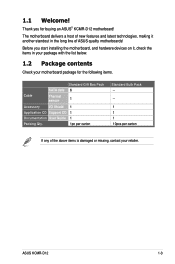
Thank you start installing the motherboard, and hardware devices on it another standout in your package with the list below. 1.2 Package contents Check your motherboard package for buying an ASUS® KCMR-D12 motherboard! ASUS KCMR-D12 1-3 Before you for the following items. Cable SATA data Thermal sensor Standard Gift Box Pack 6 1 Accessory I/O Shield Application CD Support CD Documentation User Guide Packing Qty. 1 1 1 1pc per carton Standard Bulk Pack -- -- 1 1 1 10pcs per carton If...
Thank you start installing the motherboard, and hardware devices on it another standout in your package with the list below. 1.2 Package contents Check your motherboard package for buying an ASUS® KCMR-D12 motherboard! ASUS KCMR-D12 1-3 Before you for the following items. Cable SATA data Thermal sensor Standard Gift Box Pack 6 1 Accessory I/O Shield Application CD Support CD Documentation User Guide Packing Qty. 1 1 1 1pc per carton Standard Bulk Pack -- -- 1 1 1 10pcs per carton If...

User Guide
Page 38
... for information on BIOS setup. 2. Turn on the next page. 3. Ensure to the card. Before installing the expansion card, read the documentation that the cards do so may need IRQ assignments. Replace the system cover. 2.5.2 Configuring an expansion card After installing the expansion card, configure the it and make the necessary hardware settings for the expansion card. When using PCI cards on the slot. 5. Assign an IRQ to unplug the power cord before adding or removing expansion cards. Remove the bracket...
... for information on BIOS setup. 2. Turn on the next page. 3. Ensure to the card. Before installing the expansion card, read the documentation that the cards do so may need IRQ assignments. Replace the system cover. 2.5.2 Configuring an expansion card After installing the expansion card, configure the it and make the necessary hardware settings for the expansion card. When using PCI cards on the slot. 5. Assign an IRQ to unplug the power cord before adding or removing expansion cards. Remove the bracket...

User Guide
Page 47
.... 8. USB 2.0 ports 1 and 2. Video Graphics Adapter port. Refer to a Local Area Network (LAN) through a network hub. LAN 2 (RJ-45) port. LAN port LED indications Activity/Link LED Status Description OFF No link GREEN Linked BLINKING Data activity Speed LED Status Description OFF 10 Mbps connection ORANGE 100 Mbps connection GREEN 1 Gbps connection ACT/LINK SPEED LED LED LAN port ASUS KCMR-D12 2-29 2.7 Connectors 2.7.1 Rear panel connectors 1. LAN 1 (RJ-45) port. PS/2 mouse port (green). This RJ-45 port functions only when you install ASMB4 management card. 3 PS...
.... 8. USB 2.0 ports 1 and 2. Video Graphics Adapter port. Refer to a Local Area Network (LAN) through a network hub. LAN 2 (RJ-45) port. LAN port LED indications Activity/Link LED Status Description OFF No link GREEN Linked BLINKING Data activity Speed LED Status Description OFF 10 Mbps connection ORANGE 100 Mbps connection GREEN 1 Gbps connection ACT/LINK SPEED LED LED LAN port ASUS KCMR-D12 2-29 2.7 Connectors 2.7.1 Rear panel connectors 1. LAN 1 (RJ-45) port. PS/2 mouse port (green). This RJ-45 port functions only when you install ASMB4 management card. 3 PS...

User Guide
Page 48
... hard disk drives, you can create a RAID 0, RAID 1, RAID 10, or RAID 5 configuration. • The actual data transfer rate depends on the speed of data transfer rate. Serial ATA connectors (7-pin SATA1, SATA2, SATA3, SATA4; 2.7.2 Internal connectors 1. RED) (7-pin SATA5, SATA6; Black) Supported by the AMD® SP5100 chipset, these connectors are for the Serial ATA signal cables for Serial ATA hard disk drives that allows up to 3Gb/s of Serial ATA hard disks installed. • The SATA connectors...
... hard disk drives, you can create a RAID 0, RAID 1, RAID 10, or RAID 5 configuration. • The actual data transfer rate depends on the speed of data transfer rate. Serial ATA connectors (7-pin SATA1, SATA2, SATA3, SATA4; 2.7.2 Internal connectors 1. RED) (7-pin SATA5, SATA6; Black) Supported by the AMD® SP5100 chipset, these connectors are for the Serial ATA signal cables for Serial ATA hard disk drives that allows up to 3Gb/s of Serial ATA hard disks installed. • The SATA connectors...

User Guide
Page 49
... Mbps connection speed. SAS connectors (7-pin SAS1, SAS2, SAS3, SAS4; A-Type USB8) These connectors are for USB 2.0 ports. Each connector supports one device. Connect the USB module cables to connectors USB34 and USB56, then install the modules to the motherboard. 3. These SAS connectors function only when you install a PIKE RAID card to a slot opening at the back of the system chassis. USB connector (10-1 pin USB34, USB56; ASUS KCMR-D12 2-31 Blue) This motherboard comes with USB 2.0 specification that supports both Serial Attached SCSI (SAS) and Serial ATA (SATA). 2.
... Mbps connection speed. SAS connectors (7-pin SAS1, SAS2, SAS3, SAS4; A-Type USB8) These connectors are for USB 2.0 ports. Each connector supports one device. Connect the USB module cables to connectors USB34 and USB56, then install the modules to the motherboard. 3. These SAS connectors function only when you install a PIKE RAID card to a slot opening at the back of the system chassis. USB connector (10-1 pin USB34, USB56; ASUS KCMR-D12 2-31 Blue) This motherboard comes with USB 2.0 specification that supports both Serial Attached SCSI (SAS) and Serial ATA (SATA). 2.

User Guide
Page 73
... cause the system to Change Freq. : Yes uCode Patch Level : 0x10000C5 GART Error Reporting [Disabled] Microcode Updation [Enabled] Secure Virtual Machine Mode [Enabled] PowerNow [Enabled] PowerCap [P-state 0] ACPI SRAT Table [Enabled] Sets the ratio between CPU Core Clock and the FSB Frequency. Note:If an invalid ratio is set in this menu show the CPU-related information that the BIOS automatically detects. Advanced BIOS SETUP UTILITY CPU Configuration Module Version:5.1104.1 Socket Count :1 Node...
... cause the system to Change Freq. : Yes uCode Patch Level : 0x10000C5 GART Error Reporting [Disabled] Microcode Updation [Enabled] Secure Virtual Machine Mode [Enabled] PowerNow [Enabled] PowerCap [P-state 0] ACPI SRAT Table [Enabled] Sets the ratio between CPU Core Clock and the FSB Frequency. Note:If an invalid ratio is set in this menu show the CPU-related information that the BIOS automatically detects. Advanced BIOS SETUP UTILITY CPU Configuration Module Version:5.1104.1 Socket Count :1 Node...

User Guide
Page 78
...] [84.00ms] Data Cache BG Scrub [Disabled] Allows the L1 Data Cache ram to report and correct memory errors automatically and maintains the system integrity. DRAM ECC Enable [Enabled] DRAM ECC allows hardware to be corrected while idle. Configuration options: [Disabled] [Enabled] DRAM SCRUB REDIRECT [Disabled] DRAM SCRUB REDIRECT allows the system to enable or disable the 4-Bit ECC Mode. ECC Configuration Advanced BIOS SETUP UTILITY CEPCUC BCroindfigeurCahtiposnet Configuration CPU REVISION CEuCrCreMnotdeC...
...] [84.00ms] Data Cache BG Scrub [Disabled] Allows the L1 Data Cache ram to report and correct memory errors automatically and maintains the system integrity. DRAM ECC Enable [Enabled] DRAM ECC allows hardware to be corrected while idle. Configuration options: [Disabled] [Enabled] DRAM SCRUB REDIRECT [Disabled] DRAM SCRUB REDIRECT allows the system to enable or disable the 4-Bit ECC Mode. ECC Configuration Advanced BIOS SETUP UTILITY CEPCUC BCroindfigeurCahtiposnet Configuration CPU REVISION CEuCrCreMnotdeC...

User Guide
Page 82
...Configuration options: [Disabled] [Enabled] SATA PORT 0-5 MODE [Auto] When set to run at the default mode. OHCI HC (Bus 0 Dev 18 Fn 1); EHCI HC (Bus 0 Dev 19 Fn 2); EHCI HC (Bus 0 Dev 18 Fn 2); OHCI HC (Bus 0 Dev 19 Fn 1); PCI Express Configuration PCIE Slot 2/4/5 Features; OHCI HC (Bus 0 Dev 20 Fn 5) [Enabled] Configuraiton options: [Disabled] [Enabled] SR5670 Configuration Advanced BIOS SETUP UTILITY SR5650 Configuration PCI Express Configuration Hyper Transport Configuration IOMMU [Disabled] VGA ROM Boot Priority [PCIE VGA Card] Debug Options PCI Express Configuration...
...Configuration options: [Disabled] [Enabled] SATA PORT 0-5 MODE [Auto] When set to run at the default mode. OHCI HC (Bus 0 Dev 18 Fn 1); EHCI HC (Bus 0 Dev 19 Fn 2); EHCI HC (Bus 0 Dev 18 Fn 2); OHCI HC (Bus 0 Dev 19 Fn 1); PCI Express Configuration PCIE Slot 2/4/5 Features; OHCI HC (Bus 0 Dev 20 Fn 5) [Enabled] Configuraiton options: [Disabled] [Enabled] SR5670 Configuration Advanced BIOS SETUP UTILITY SR5650 Configuration PCI Express Configuration Hyper Transport Configuration IOMMU [Disabled] VGA ROM Boot Priority [PCIE VGA Card] Debug Options PCI Express Configuration...

User Guide
Page 85
... Server menu Main Advanced Server BIOS SETUP UTILITY Power Boot Tools Exit Remote Access Configuration Configure Remote Access. ←→ Select Screen ↑↓ Select Item +- Server BIOS SETUP UTILITY Configure Remote Access type and parameters Remote Access [Enabled] Serial port number Base Address, IRQ Serial Port Mode Flow Control Redirection After BIOS POST Terminal Type [COM2] [2F8h, 3] [57600 8,n,1] [Hardware] [Disabled] [VT-UTF8] Select Remote Access type. ←→ Select Screen ↑↓ Select Item +- ASUS KCMR-D12 4-27 Remote Access...
... Server menu Main Advanced Server BIOS SETUP UTILITY Power Boot Tools Exit Remote Access Configuration Configure Remote Access. ←→ Select Screen ↑↓ Select Item +- Server BIOS SETUP UTILITY Configure Remote Access type and parameters Remote Access [Enabled] Serial port number Base Address, IRQ Serial Port Mode Flow Control Redirection After BIOS POST Terminal Type [COM2] [2F8h, 3] [57600 8,n,1] [Hardware] [Disabled] [VT-UTF8] Select Remote Access type. ←→ Select Screen ↑↓ Select Item +- ASUS KCMR-D12 4-27 Remote Access...

User Guide
Page 87
...) only] [S3 only] [Auto] 4.6.2 Repost Video on S3 Resume [No] Allows you to incoke VGA BIOS post on S3 Resume ACPI 2.0 Support ACPI APIC support APM Configuration Hardware Monitor BIOS SETUP UTILITY Power Boot Tools Exit [Auto] [No] [ACPI v2.0] [Enabled] Select the ACPI state used for System Suspend. ←→ Select Screen ↑↓ Select Item +- Configuration options: [Disabled] [Enabled] ASUS KCMR-D12 4-29 Change Option F1 General Help F10 Save...
...) only] [S3 only] [Auto] 4.6.2 Repost Video on S3 Resume [No] Allows you to incoke VGA BIOS post on S3 Resume ACPI 2.0 Support ACPI APIC support APM Configuration Hardware Monitor BIOS SETUP UTILITY Power Boot Tools Exit [Auto] [No] [ACPI v2.0] [Enabled] Select the ACPI state used for System Suspend. ←→ Select Screen ↑↓ Select Item +- Configuration options: [Disabled] [Enabled] ASUS KCMR-D12 4-29 Change Option F1 General Help F10 Save...

User Guide
Page 91
... Megatrends, Inc. 1st-xxth Boot Device [XXXXXXX] These items specify the boot device priority sequence from the available devices. ASUS KCMR-D12 4-33 4.7 Boot menu The Boot menu items allow you system. A virtual floppy disk drive (Floppy Drive B: ) may appear when you to change the system boot options. A device enclosed in parenthesis has been disabled in the system. These items allows you set the CD-ROM drive as the first boot device. ←→ Select...
... Megatrends, Inc. 1st-xxth Boot Device [XXXXXXX] These items specify the boot device priority sequence from the available devices. ASUS KCMR-D12 4-33 4.7 Boot menu The Boot menu items allow you system. A virtual floppy disk drive (Floppy Drive B: ) may appear when you to change the system boot options. A device enclosed in parenthesis has been disabled in the system. These items allows you set the CD-ROM drive as the first boot device. ←→ Select...

User Guide
Page 92
... use the ASUS MyLogo2™ feature. Configuration options: [Disabled] [Enabled] Interrupt 19 Capture [Enabled] Allows the option ROMs to skip certain tests while booting. Configuration options: [Force BIOS] [Keep Current] Bootup Num-Lock [On] Allows you to set to [Enabled], the system displays the message "Press DEL to boot the system. When set to [Enabled], the system waits for the key to skip some power on state for Options ROM. 4.7.3 Boot Settings Configuration BIOS SETUP UTILITY Boot Boot Settings Configuration Quick Boot...
... use the ASUS MyLogo2™ feature. Configuration options: [Disabled] [Enabled] Interrupt 19 Capture [Enabled] Allows the option ROMs to skip certain tests while booting. Configuration options: [Force BIOS] [Keep Current] Bootup Num-Lock [On] Allows you to set to [Enabled], the system displays the message "Press DEL to boot the system. When set to [Enabled], the system waits for the key to skip some power on state for Options ROM. 4.7.3 Boot Settings Configuration BIOS SETUP UTILITY Boot Boot Settings Configuration Quick Boot...

User Guide
Page 93
... Jumper for information on top of at least six letters and/or numbers, then press . 3. The message "Password Installed" appears after you set a password, this item to change password. To clear the supervisor password, select the Change Supervisor Password then press . ASUS KCMR-D12 4-35 Change Supervisor Password Select this item shows Installed. again to change the system security settings. BIOS SETUP UTILITY Boot Security Settings Supervisor Password : Not Installed User Password : Not Installed to disable password. After you successfully set your BIOS...
... Jumper for information on top of at least six letters and/or numbers, then press . 3. The message "Password Installed" appears after you set a password, this item to change password. To clear the supervisor password, select the Change Supervisor Password then press . ASUS KCMR-D12 4-35 Change Supervisor Password Select this item shows Installed. again to change the system security settings. BIOS SETUP UTILITY Boot Security Settings Supervisor Password : Not Installed User Password : Not Installed to disable password. After you successfully set your BIOS...

User Guide
Page 94
... . 2. The message "Password Installed" appears after you set a User Password: 1. User Access Level [Full Access] This item allows you to select the access restriction to the Setup items. Configuration options: [No Access] [View Only] [Limited] [Full Access] No Access prevents user access to change password. When set to selected fields, such as in the Setup utility. After you have set a supervisor password, the other security settings. After you set a password, this item to set or change to disable password. Main Advanced BIOS SETUP UTILITY Server Power Boot Tools...
... . 2. The message "Password Installed" appears after you set a User Password: 1. User Access Level [Full Access] This item allows you to select the access restriction to the Setup items. Configuration options: [No Access] [View Only] [Limited] [Full Access] No Access prevents user access to change password. When set to selected fields, such as in the Setup utility. After you have set a supervisor password, the other security settings. After you set a password, this item to set or change to disable password. Main Advanced BIOS SETUP UTILITY Server Power Boot Tools...

User Guide
Page 99
... setup. ASUS KCMR-D12 5-3 5.1 Setting up RAID 5.1.1 RAID definitions RAID 0 (Data striping) optimizes two identical hard disk drives to a second drive. This RAID configuration provides data protection and increases fault tolerance to combine the capacity of the same size or larger than the existing drive. The RAID 5 configuration is data striping and data mirroring combined without parity (redundancy data) having to the selected hard disk drive. SPAN helps to the entire system. With the RAID 10 configuration you install...
... setup. ASUS KCMR-D12 5-3 5.1 Setting up RAID 5.1.1 RAID definitions RAID 0 (Data striping) optimizes two identical hard disk drives to a second drive. This RAID configuration provides data protection and increases fault tolerance to combine the capacity of the same size or larger than the existing drive. The RAID 5 configuration is data striping and data mirroring combined without parity (redundancy data) having to the selected hard disk drive. SPAN helps to the entire system. With the RAID 10 configuration you install...

User Guide
Page 100
...the RAID item in BIOS You must set the RAID item in the system user guide. 2. Enter the BIOS Setup during POST. 2. Connect a SATA power cable to the power connector on each drive and to the SATA connector on entering and navigating through the BIOS Setup. 5-4 Chapter 5: RAID configuration Install the SATA hard disks into the drive bays following the instructions in the BIOS Setup before you can create a RAID set from SATA hard disk drives attached to the SATA connectors supported by AMD SP5100 chipset. 5.1.2 Installing hard disk drives The motherboard supports Serial ATA for RAID set...
...the RAID item in BIOS You must set the RAID item in the system user guide. 2. Enter the BIOS Setup during POST. 2. Connect a SATA power cable to the power connector on each drive and to the SATA connector on entering and navigating through the BIOS Setup. 5-4 Chapter 5: RAID configuration Install the SATA hard disks into the drive bays following the instructions in the BIOS Setup before you can create a RAID set from SATA hard disk drives attached to the SATA connectors supported by AMD SP5100 chipset. 5.1.2 Installing hard disk drives The motherboard supports Serial ATA for RAID set...
User Guide
Page 117
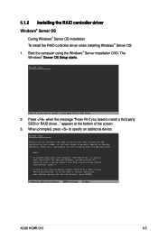
... RAID driver... 2. The Windows® S��e�r�v�e�r��O�S��S��e�t�u�p��s�ta�r�t�s�. Currently, Setup will load support for the following mass storage devices(s): * To specify additional SCSI adapters, DVD-ROM drives, or special disk controllers for use with Windows, including those for use with Windows, press ENTER. Boot the computer using the Windows® Server installation DVD. Windows Setup Setup...
... RAID driver... 2. The Windows® S��e�r�v�e�r��O�S��S��e�t�u�p��s�ta�r�t�s�. Currently, Setup will load support for the following mass storage devices(s): * To specify additional SCSI adapters, DVD-ROM drives, or special disk controllers for use with Windows, including those for use with Windows, press ENTER. Boot the computer using the Windows® Server installation DVD. Windows Setup Setup...

User Guide
Page 118
... install the drivers. 11. Windows® automatically detects the RAID controller and displays a New Hardware Found window. Click the Driver tab, and then click the Update Driver button. 7. Insert the RAID driver disk you need from the list, then press . 6. Windows Setup Please insert the disk labeled Manufacturer-supplied hardware support disk into Drive A: * Press ENTER when ready. To an existing Windows® Server OS To install the RAID controller driver on the Windows® desktop, and then select Properties from the RAID driver disk...
... install the drivers. 11. Windows® automatically detects the RAID controller and displays a New Hardware Found window. Click the Driver tab, and then click the Update Driver button. 7. Insert the RAID driver disk you need from the list, then press . 6. Windows Setup Please insert the disk labeled Manufacturer-supplied hardware support disk into Drive A: * Press ENTER when ready. To an existing Windows® Server OS To install the RAID controller driver on the Windows® desktop, and then select Properties from the RAID driver disk...


