User Guide
Page 11
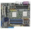
K8N-DL specifications summary Internal connectors Rear panel BIOS features Power Requirement Form Factor Support CD contents 1 x Floppy disk drive connector 2 x IDE connectors 4 x Serial ATA connectors 4 x RAID Serial ATA connectors 2 x CPU fan connectors 2 x front fan connector 2 x rear fan connector 1 x Chipset fan connector 1 x 24-pin ATX power connector 1 x 8-pin ATX 12 V power... PS/2 mouse port 8-channel audio ports 4 Mb Flash ROM, Phoenix-Award BIOS, PnP, DMI2.0, WfM2.0, SM BIOS 2.3 ATX power supply (with 24-pin and 8-pin 12 V plugs) ATX 12 V 2.0 compliant ATX form factor: 12 in x 10.5 ...
K8N-DL specifications summary Internal connectors Rear panel BIOS features Power Requirement Form Factor Support CD contents 1 x Floppy disk drive connector 2 x IDE connectors 4 x Serial ATA connectors 4 x RAID Serial ATA connectors 2 x CPU fan connectors 2 x front fan connector 2 x rear fan connector 1 x Chipset fan connector 1 x 24-pin ATX power connector 1 x 8-pin ATX 12 V power... PS/2 mouse port 8-channel audio ports 4 Mb Flash ROM, Phoenix-Award BIOS, PnP, DMI2.0, WfM2.0, SM BIOS 2.3 ATX power supply (with 24-pin and 8-pin 12 V plugs) ATX 12 V 2.0 compliant ATX form factor: 12 in x 10.5 ...
User Guide
Page 21
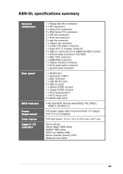
...pad or in the bag that came with a green standby power LED that lights up to indicate that your power supply unit (PSU) can provide at least the minimum power required by the edges to the motherboard, peripherals, and/or ... soft-off or the p o w e r c o r d i s d e t a c h e d f r o m t h e p o w e r s u p p l y . This is switched off mode. SB_PWR1 ® K8N-DL K8N-DL Standby power LED ON Standby Power OFF Powered Off ASUS K8N-DL 2-1 See "8. Onboard LEDs 1. 2.1 Before you proceed Take note of the following precautions before removing or plugging in any motherboard component.
...pad or in the bag that came with a green standby power LED that lights up to indicate that your power supply unit (PSU) can provide at least the minimum power required by the edges to the motherboard, peripherals, and/or ... soft-off or the p o w e r c o r d i s d e t a c h e d f r o m t h e p o w e r s u p p l y . This is switched off mode. SB_PWR1 ® K8N-DL K8N-DL Standby power LED ON Standby Power OFF Powered Off ASUS K8N-DL 2-1 See "8. Onboard LEDs 1. 2.1 Before you proceed Take note of the following precautions before removing or plugging in any motherboard component.

User Guide
Page 38
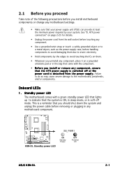
...(Default) 2 3 +5VSB ® K8N-DL K8N-DL Keyboard power setting 3 . 1394 controller setting (3-pin 1394_EN1) This jumper allows you to wake up feature. Set to pins 1-2 to enable or disable the onboard TI 1394a IEEE 1394 controller. This feature requires an ATX power supply that can supply at least 1A ...on the keyboard (the default is the Space Bar). Keyboard power (3-pin KBPWR1) This jumper allows you to activate the 1394 feature. ® K8N-DL K8N-DL 1394 function setting 1394_EN 12 ...
...(Default) 2 3 +5VSB ® K8N-DL K8N-DL Keyboard power setting 3 . 1394 controller setting (3-pin 1394_EN1) This jumper allows you to wake up feature. Set to pins 1-2 to enable or disable the onboard TI 1394a IEEE 1394 controller. This feature requires an ATX power supply that can supply at least 1A ...on the keyboard (the default is the Space Bar). Keyboard power (3-pin KBPWR1) This jumper allows you to activate the 1394 feature. ® K8N-DL K8N-DL 1394 function setting 1394_EN 12 ...
User Guide
Page 47
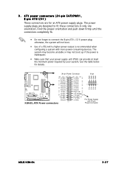
...with a higher power output is inadequate. • Make sure that your power supply unit (PSU) can provide at least the minimum power required by your system. ATX power connectors (24-pin EATXPWR1, 8-pin ATX12V1) These connectors are designed to connect the 8-pin ATX +12 V power plug; Find ...become unstable or may not boot up if the power is recommended when configuring a system with 20-pin Power Connector 12V 12V ASUS K8N-DL 2-27 The power supply plugs are for details. 24-pin Power Connector 8-pin GND GND GND GND ® K8N-DL +3 Volts -12 Volts Ground PSON# Ground Ground...
...with a higher power output is inadequate. • Make sure that your power supply unit (PSU) can provide at least the minimum power required by your system. ATX power connectors (24-pin EATXPWR1, 8-pin ATX12V1) These connectors are designed to connect the 8-pin ATX +12 V power plug; Find ...become unstable or may not boot up if the power is recommended when configuring a system with 20-pin Power Connector 12V 12V ASUS K8N-DL 2-27 The power supply plugs are for details. 24-pin Power Connector 8-pin GND GND GND GND ® K8N-DL +3 Volts -12 Volts Ground PSON# Ground Ground...
User Guide
Page 50
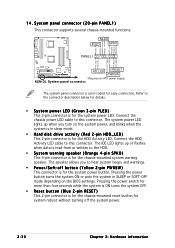
... supports several chassis-mounted functions. PWR GND Reset GND ® K8N-DL HD_LED RESET PWRSW * Requires an ATX power supply. 14. MLED PLED SPKO PLED+ PLEDMLED+ MLED+5V Ground Ground Speaker PANEL1 HD_LED+ HD_LED- The speaker allows you turn on the BIOS settings. K8N-DL System panel connector The system panel connector is for easy connection...
... supports several chassis-mounted functions. PWR GND Reset GND ® K8N-DL HD_LED RESET PWRSW * Requires an ATX power supply. 14. MLED PLED SPKO PLED+ PLEDMLED+ MLED+5V Ground Ground Speaker PANEL1 HD_LED+ HD_LED- The speaker allows you turn on the BIOS settings. K8N-DL System panel connector The system panel connector is for easy connection...

User Guide
Page 56
See section 4.4.4 for assistance. See the "ASUS contact information" on after you apply power to the system. • Make sure that your CPU fan supports the fan speed detection function. • Check your power supply and make sure it is working properly. • Check...; Check if the CPU fan is not defective. • Call ASUS technical support for details. 3-4 Chapter 3: Powering up POST Message CPU temperature too high CPU fan failed CPU voltage out of this user guide. • No action required You can enable or disable the ASUS POST Reporter™ in the S p e e c h I C R e ...
See section 4.4.4 for assistance. See the "ASUS contact information" on after you apply power to the system. • Make sure that your CPU fan supports the fan speed detection function. • Check your power supply and make sure it is working properly. • Check...; Check if the CPU fan is not defective. • Call ASUS technical support for details. 3-4 Chapter 3: Powering up POST Message CPU temperature too high CPU fan failed CPU voltage out of this user guide. • No action required You can enable or disable the ASUS POST Reporter™ in the S p e e c h I C R e ...

User Guide
Page 73
...prompted to use as possible. This requires you to reconfigure your system using the BIOS Setup program so that you wish to enter Setup after changing any BIOS settings, load the default settings to ensure system compatibility and stability. Press during the Power-On Self-Test (POST) to run...utility. See section "4.7 Exit Menu." • The BIOS setup screens shown in the future. ASUS K8N-DL 4-11 Being a menu-driven program, it as easy to use the Setup program, you can change the power management settings. Use the BIOS Setup program when you are for reference purposes only, and may ...
...prompted to use as possible. This requires you to reconfigure your system using the BIOS Setup program so that you wish to enter Setup after changing any BIOS settings, load the default settings to ensure system compatibility and stability. Press during the Power-On Self-Test (POST) to run...utility. See section "4.7 Exit Menu." • The BIOS setup screens shown in the future. ASUS K8N-DL 4-11 Being a menu-driven program, it as easy to use the Setup program, you can change the power management settings. Use the BIOS Setup program when you are for reference purposes only, and may ...
User Guide
Page 77
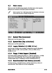
...1.44 MB) data on the menu screen items and how to support Japanese standard floppy drives. ASUS K8N-DL 4-15 Phoenix-Award BIOS CMOS Setup Utility Main Advanced Power Boot Exit System Time System Date Legacy Diskette A Floppy 3 Mode Support Primary IDE Master Primary...] [None] [None] [None] [None] [None] [None] [None] xxxK xxxxxxK xxxxxxK Select Menu Item Specific Help Change the internal clock. This is required to navigate through them. These fields are auto-detected. Refer to section "4.2.1 BIOS menu screen" for information on a 3.5-inch floppy disk. Configuration options: [Disabled...
...1.44 MB) data on the menu screen items and how to support Japanese standard floppy drives. ASUS K8N-DL 4-15 Phoenix-Award BIOS CMOS Setup Utility Main Advanced Power Boot Exit System Time System Date Legacy Diskette A Floppy 3 Mode Support Primary IDE Master Primary...] [None] [None] [None] [None] [None] [None] [None] xxxK xxxxxxK xxxxxxK Select Menu Item Specific Help Change the internal clock. This is required to navigate through them. These fields are auto-detected. Refer to section "4.2.1 BIOS menu screen" for information on a 3.5-inch floppy disk. Configuration options: [Disabled...

User Guide
Page 98
This feature requires an ATX power supply that provides at least 1A on the system. Configuration options: [Disabled] [Enabled] 4.5.2 Hardware Monitor This menu shows the hardware monitoring status. Select an item, ... Select Menu Item Specific Help Press enter to display a pop-up menu with the configuration options. Configuration options: [Disabled] [Ctrl+ESC] [Space Bar] [Power Key] [Any Key] Power Up By PS/2 Mouse [Disabled] When set to [Enabled], this parameter allows you to define specific keys on the keyboard to turn on the...
This feature requires an ATX power supply that provides at least 1A on the system. Configuration options: [Disabled] [Enabled] 4.5.2 Hardware Monitor This menu shows the hardware monitoring status. Select an item, ... Select Menu Item Specific Help Press enter to display a pop-up menu with the configuration options. Configuration options: [Disabled] [Ctrl+ESC] [Space Bar] [Power Key] [Any Key] Power Up By PS/2 Mouse [Disabled] When set to [Enabled], this parameter allows you to define specific keys on the keyboard to turn on the...

User Guide
Page 106
... options: [Setup] [System] 4-44 Chapter 4: BIOS setup Forgot your password, you to require the password before entering the BIOS setup or the system. The RAM data containing the password information is powered by erasing the CMOS Real Time Clock (RTC) RAM. If you forget your password? A... note about passwords The Supervisor password is required to section "2.6 Jumpers" for instructions. If you need to erase the...
... options: [Setup] [System] 4-44 Chapter 4: BIOS setup Forgot your password, you to require the password before entering the BIOS setup or the system. The RAM data containing the password information is powered by erasing the CMOS Real Time Clock (RTC) RAM. If you forget your password? A... note about passwords The Supervisor password is required to section "2.6 Jumpers" for instructions. If you need to erase the...


