
User Guide
Page 3
Contents Contents Safety information...iv About this guide...iv Package contents...vi H97M-E specifications summary vi Product introduction 1-1 1.1 Before you proceed 1-1 1.2 Motherboard overview 1-1 1.3 Central Processing Unit (CPU 1-3 1.4 System memory 1-6 1.5 Expansion slots 1-9 1.6 Jumpers...1-10 1.7 Connectors 1-11 1.8 Onboard LEDs 1-19 1.9 ...2.4 Main menu...2-11 2.5 Ai Tweaker menu 2-11 2.6 Advanced menu 2-13 2.7 Monitor menu 2-14 2.8 Boot menu...2-15 2.9 Tools menu 2-16 2.10 Exit menu...2-16 Appendices A-1 Notices...A-1 ASUS contact information A-3 iii
Contents Contents Safety information...iv About this guide...iv Package contents...vi H97M-E specifications summary vi Product introduction 1-1 1.1 Before you proceed 1-1 1.2 Motherboard overview 1-1 1.3 Central Processing Unit (CPU 1-3 1.4 System memory 1-6 1.5 Expansion slots 1-9 1.6 Jumpers...1-10 1.7 Connectors 1-11 1.8 Onboard LEDs 1-19 1.9 ...2.4 Main menu...2-11 2.5 Ai Tweaker menu 2-11 2.6 Advanced menu 2-13 2.7 Monitor menu 2-14 2.8 Boot menu...2-15 2.9 Tools menu 2-16 2.10 Exit menu...2-16 Appendices A-1 Notices...A-1 ASUS contact information A-3 iii
User Guide
Page 6
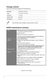
... Technology 2.0* * The Intel® Turbo Boost Technology 2.0 support depends on the CPU types. ** Refer to www.asus.com for the following items. Motherboard Cables Accessories Application DVD Documentation ASUS H97M-E motherboard 2 x Serial ATA 6.0 Gb/s cables 1 x I/O Shield Support DVD User Guide If any of DDR3 ...DDR3 1600/ 1333 MHz, non-ECC, un-buffered memory Dual-channel memory architecture Supports Intel® Extreme Memory Profile (XMP) * Due to www.asus.com for the Memory QVL (Qualified Vendors List). 1 x PCI Express 3.0/2.0 x16 slot (at x16 mode) 3 x PCI Express 2.0 x1 slots ...
... Technology 2.0* * The Intel® Turbo Boost Technology 2.0 support depends on the CPU types. ** Refer to www.asus.com for the following items. Motherboard Cables Accessories Application DVD Documentation ASUS H97M-E motherboard 2 x Serial ATA 6.0 Gb/s cables 1 x I/O Shield Support DVD User Guide If any of DDR3 ...DDR3 1600/ 1333 MHz, non-ECC, un-buffered memory Dual-channel memory architecture Supports Intel® Extreme Memory Profile (XMP) * Due to www.asus.com for the Memory QVL (Qualified Vendors List). 1 x PCI Express 3.0/2.0 x16 slot (at x16 mode) 3 x PCI Express 2.0 x1 slots ...

User Guide
Page 11
... it into the chassis in the image. 1.2.2 Screw holes Place six screws into the holes indicated by circles to secure the motherboard to the chassis. ASUS H97M-E 1-1 The edge with the component. • Before you install or remove any component, ensure that the motherboard fits. Unplug the power cord before touching any...
... it into the chassis in the image. 1.2.2 Screw holes Place six screws into the holes indicated by circles to secure the motherboard to the chassis. ASUS H97M-E 1-1 The edge with the component. • Before you install or remove any component, ensure that the motherboard fits. Unplug the power cord before touching any...
User Guide
Page 13
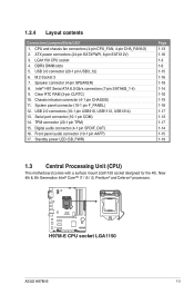
..., Pentium® and Celeron® processors. ATX power connectors (24-pin EATXPWR, 8-pin EATX12V) 3. Clear RTC RAM (3-pin CLRTC) 10. USB 3.0 connector (20-1 pin USB3_12) 6. H97M-E H97M-E CPU socket LGA1150 ASUS H97M-E 1-3 CPU and chassis fan connectors (4-pin CPU_FAN, 4-pin CHA_FAN1/2) 2.
..., Pentium® and Celeron® processors. ATX power connectors (24-pin EATXPWR, 8-pin EATX12V) 3. Clear RTC RAM (3-pin CLRTC) 10. USB 3.0 connector (20-1 pin USB3_12) 6. H97M-E H97M-E CPU socket LGA1150 ASUS H97M-E 1-3 CPU and chassis fan connectors (4-pin CPU_FAN, 4-pin CHA_FAN1/2) 2.

User Guide
Page 15
4 C 5 A B 1.3.2 CPU heatsink and fan assembly installation Apply the Thermal Interface Material to the CPU heatsink and CPU before you install the heatsink and fan if necessary. To install the CPU heatsink and fan assembly 1 A B 2 B A ASUS H97M-E 1-5
4 C 5 A B 1.3.2 CPU heatsink and fan assembly installation Apply the Thermal Interface Material to the CPU heatsink and CPU before you install the heatsink and fan if necessary. To install the CPU heatsink and fan assembly 1 A B 2 B A ASUS H97M-E 1-5
User Guide
Page 17
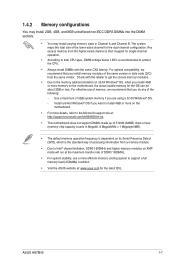
... to Intel® chipset limitation, DDR3 1600MHz and higher memory modules on the motherboard, the actual usable memory for the dual-channel configuration. ASUS H97M-E 1-7 For optimal compatibility, we recommend that you do any of 512Mb (64MB) chips or less (memory chip capacity counts in Channel A...when you install 4GB or more efficient memory cooling system to support a full memory load (4 DIMMs) condition. • Visit the ASUS website at: www.asus.com for single-channel operation. • According to Intel CPU spec, DIMM voltage below 1.65V is recommended to protect the CPU....
... to Intel® chipset limitation, DDR3 1600MHz and higher memory modules on the motherboard, the actual usable memory for the dual-channel configuration. ASUS H97M-E 1-7 For optimal compatibility, we recommend that you do any of 512Mb (64MB) chips or less (memory chip capacity counts in Channel A...when you install 4GB or more efficient memory cooling system to support a full memory load (4 DIMMs) condition. • Visit the ASUS website at: www.asus.com for single-channel operation. • According to Intel CPU spec, DIMM voltage below 1.65V is recommended to protect the CPU....

User Guide
Page 19
... using PCI cards on the slot. 5. Keep the screw for the card. 2. Secure the card to install expansion cards. See Chapter 2 for the expansion card. ASUS H97M-E 1-9 Replace the system cover. 1.5.2 Configuring an expansion card After installing the expansion card, configure it and make the necessary hardware settings for later use . Remove...
... using PCI cards on the slot. 5. Keep the screw for the card. 2. Secure the card to install expansion cards. See Chapter 2 for the expansion card. ASUS H97M-E 1-9 Replace the system cover. 1.5.2 Configuring an expansion card After installing the expansion card, configure it and make the necessary hardware settings for later use . Remove...
User Guide
Page 21
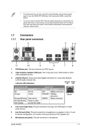
... Orange (Blinking Ready to overclocking, use the CPU Parameter Recall (C.P.R.) feature. In the 4, 6, and 8-channel configurations, the function of this port becomes Front Speaker Out. 6. ASUS H97M-E 1-11 For system failure due to wake then steady) up from S5 mode Speed LED Status Description OFF 10Mbps connection ORANGE 100Mbps connection GREEN 1Gbps...
... Orange (Blinking Ready to overclocking, use the CPU Parameter Recall (C.P.R.) feature. In the 4, 6, and 8-channel configurations, the function of this port becomes Front Speaker Out. 6. ASUS H97M-E 1-11 For system failure due to wake then steady) up from S5 mode Speed LED Status Description OFF 10Mbps connection ORANGE 100Mbps connection GREEN 1Gbps...
User Guide
Page 23
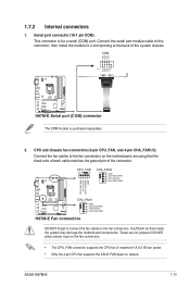
... that the black wire of each cable matches the ground pin of the connector. COM PIN 1 RXD DTR DSR CTS DCD TXD GND RTS RI H97M-E H97M-E Serial port (COM) connector The COM module is for a serial (COM) port. Insufficient air flow inside the system may damage the motherboard components. These..., then install the module to a slot opening at the back of maximum 1A (12 W) fan power. • Only the 4-pin CPU fan supports the ASUS FAN Xpert 2+ feature. ASUS H97M-E 1-13 1.7.2 Internal connectors 1. Serial port connector (10-1 pin COM) This connector is purchased separately. 2.
... that the black wire of each cable matches the ground pin of the connector. COM PIN 1 RXD DTR DSR CTS DCD TXD GND RTS RI H97M-E H97M-E Serial port (COM) connector The COM module is for a serial (COM) port. Insufficient air flow inside the system may damage the motherboard components. These..., then install the module to a slot opening at the back of maximum 1A (12 W) fan power. • Only the 4-pin CPU fan supports the ASUS FAN Xpert 2+ feature. ASUS H97M-E 1-13 1.7.2 Internal connectors 1. Serial port connector (10-1 pin COM) This connector is purchased separately. 2.
User Guide
Page 25
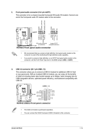
... front panel audio I/O module cable to connect a USB 3.0 module for a chassis-mounted front panel HD audio I/O module. ASUS H97M-E 1-15 Connect one end of USB 3.0 including faster data transfer speeds up to [HD] or [AC97]. 6. H97M-E USB3_12 USB3+5V IntA_P2_SSRXIntA_P2_SSRX+ GND IntA_P2_SSTXIntA_P2_SSTX+ GND IntA_P2_DIntA_P2_D+ PIN 1 USB3+5V IntA_P1_SSRXIntA_P1_SSRX+ GND IntA_P1_SSTXIntA_P1_SSTX+ GND IntA_P1_DIntA_P1_D+ GND...
... front panel audio I/O module cable to connect a USB 3.0 module for a chassis-mounted front panel HD audio I/O module. ASUS H97M-E 1-15 Connect one end of USB 3.0 including faster data transfer speeds up to [HD] or [AC97]. 6. H97M-E USB3_12 USB3+5V IntA_P2_SSRXIntA_P2_SSRX+ GND IntA_P2_SSTXIntA_P2_SSTX+ GND IntA_P2_DIntA_P2_D+ PIN 1 USB3+5V IntA_P1_SSRXIntA_P1_SSRX+ GND IntA_P1_SSTXIntA_P1_SSTX+ GND IntA_P1_DIntA_P1_D+ GND...
User Guide
Page 27
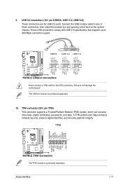
... USB+5V USB_P9USB_P9+ GND NC USB+5V USB_P11USB_P11+ GND NC USB+5V USB_P13USB_P13+ GND NC H97M-E PIN 1 PIN 1 PIN 1 USB+5V USB_P10USB_P10+ GND USB+5V USB_P12USB_P12+ GND USB+5V USB_P14USB_P14+ GND H97M-E USB2.0 connectors Never connect a 1394 cable to 480 Mbps connection speed. TPM connector (20...Connector The TPM module is purchased separately. 10. These USB connectors comply with USB 2.0 specification that supports up to the USB connectors. ASUS H97M-E 1-17 USB 2.0 connectors (10-1 pin USB910, USB1112, USB1314) These connectors are for USB 2.0 ports. Doing so will damage the...
... USB+5V USB_P9USB_P9+ GND NC USB+5V USB_P11USB_P11+ GND NC USB+5V USB_P13USB_P13+ GND NC H97M-E PIN 1 PIN 1 PIN 1 USB+5V USB_P10USB_P10+ GND USB+5V USB_P12USB_P12+ GND USB+5V USB_P14USB_P14+ GND H97M-E USB2.0 connectors Never connect a 1394 cable to 480 Mbps connection speed. TPM connector (20...Connector The TPM module is purchased separately. 10. These USB connectors comply with USB 2.0 specification that supports up to the USB connectors. ASUS H97M-E 1-17 USB 2.0 connectors (10-1 pin USB910, USB1112, USB1314) These connectors are for USB 2.0 ports. Doing so will damage the...
User Guide
Page 29
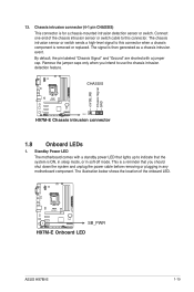
... intrusion connector 1.8 Onboard LEDs 1. The illustration below shows the location of the chassis intrusion sensor or switch cable to this connector. H97M-E SB_PWR H97M-E Onboard LED ASUS H97M-E 1-19 +5VSB_MB Chassis Signal GND 13. Chassis intrusion connector (4-1 pin CHASSIS) This connector is then generated as a chassis intrusion event. By default, the pin labeled "...
... intrusion connector 1.8 Onboard LEDs 1. The illustration below shows the location of the chassis intrusion sensor or switch cable to this connector. H97M-E SB_PWR H97M-E Onboard LED ASUS H97M-E 1-19 +5VSB_MB Chassis Signal GND 13. Chassis intrusion connector (4-1 pin CHASSIS) This connector is then generated as a chassis intrusion event. By default, the pin labeled "...
User Guide
Page 31
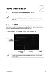
... in the future. To launch EZ Update, click EZ Update on the AI Suite 3 main menu bar. ASUS H97M-E 2-1 With this utlity, you need to automatically update your motherboard's driver, software and firmware Model Name: H97M-E Version: 0301 Release Date: 03/08/2014 Click to find and select the BIOS from file Click...
... in the future. To launch EZ Update, click EZ Update on the AI Suite 3 main menu bar. ASUS H97M-E 2-1 With this utlity, you need to automatically update your motherboard's driver, software and firmware Model Name: H97M-E Version: 0301 Release Date: 03/08/2014 Click to find and select the BIOS from file Click...
User Guide
Page 33
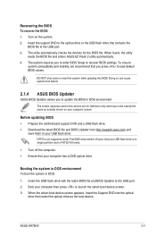
... Updater allows you to update the BIOS in DOS: 1. The screen captures used in this section are for the BIOS file. ASUS H97M-E 2-3 NTFS is in single partition and in your computer has a DVD optical drive. Booting the system in DOS environment To boot the system in ... Before updating BIOS • Prepare the motherboard support DVD and a USB flash drive. • Download the latest BIOS file and BIOS Updater from http://support.asus.com and save them in FAT32/16 format. • Turn off the computer. • Ensure that contains the BIOS file to recover BIOS settings. Turn...
... Updater allows you to update the BIOS in DOS: 1. The screen captures used in this section are for the BIOS file. ASUS H97M-E 2-3 NTFS is in single partition and in your computer has a DVD optical drive. Booting the system in DOS environment To boot the system in ... Before updating BIOS • Prepare the motherboard support DVD and a USB flash drive. • Download the latest BIOS file and BIOS Updater from http://support.asus.com and save them in FAT32/16 format. • Turn off the computer. • Ensure that contains the BIOS file to recover BIOS settings. Turn...
User Guide
Page 35
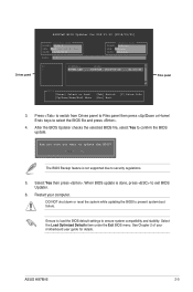
...you sure you want to prevent system boot failure. DO NOT shut down or reset the system while updating the BIOS to update the BIOS? ASUS H97M-E 2-5 When BIOS update is not supported due to security regulations. 5. Select the Load Optimized Defaults item under the Exit BIOS menu. See Chapter... keys to confirm the BIOS update. Select Yes then press . Restart your motherboard user guide for DOS V1.30 [2014/01/01] Current ROM BOARD: H97M-E VER: 0210 (H :00 B :00) DATE: 03/12/2014 PATH: C:\ Update ROM BOARD: Unknown VER: Unknown DATE: Unknown C: FORMAN~1 D: H97ME.CAP 8390626 ...
...you sure you want to prevent system boot failure. DO NOT shut down or reset the system while updating the BIOS to update the BIOS? ASUS H97M-E 2-5 When BIOS update is not supported due to security regulations. 5. Select the Load Optimized Defaults item under the Exit BIOS menu. See Chapter... keys to confirm the BIOS update. Select Yes then press . Restart your motherboard user guide for DOS V1.30 [2014/01/01] Current ROM BOARD: H97M-E VER: 0210 (H :00 B :00) DATE: 03/12/2014 PATH: C:\ Update ROM BOARD: Unknown VER: Unknown DATE: Unknown C: FORMAN~1 D: H97ME.CAP 8390626 ...
User Guide
Page 37
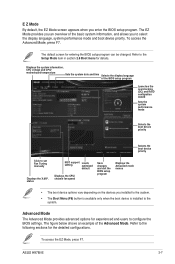
To access the Advanced Mode, press F7. ASUS H97M-E 2-7 E Z Mode By default, the EZ Mode screen appears when you installed to the system. • The Boot Menu (F8) button is available only when the ...
To access the Advanced Mode, press F7. ASUS H97M-E 2-7 E Z Mode By default, the EZ Mode screen appears when you installed to the system. • The Boot Menu (F8) button is available only when the ...

User Guide
Page 39
... display a list of the selected item. To display the submenu, select the item and press . You cannot select an item that is highlighted when selected. ASUS H97M-E 2-9 Drop-down list Select a menu item and press to display a drop-down list with the configuration options for the menu items. If an item is...
... display a list of the selected item. To display the submenu, select the item and press . You cannot select an item that is highlighted when selected. ASUS H97M-E 2-9 Drop-down list Select a menu item and press to display a drop-down list with the configuration options for the menu items. If an item is...
User Guide
Page 41
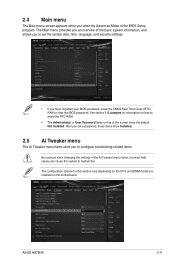
... The Main menu screen appears when you have forgotten your BIOS password, erase the CMOS Real Time Clock (RTC) RAM to clear the BIOS password. ASUS H97M-E 2-11 The Main menu provides you an overview of the BIOS Setup program.
... The Main menu screen appears when you have forgotten your BIOS password, erase the CMOS Real Time Clock (RTC) RAM to clear the BIOS password. ASUS H97M-E 2-11 The Main menu provides you an overview of the BIOS Setup program.

User Guide
Page 43
Be cautious when changing the settings of the Advanced menu items. Incorrect field values can cause the system to change the settings for the CPU and other system devices. ASUS H97M-E 2-13 2.6 Advanced menu The Advanced menu items allow you to malfunction.
Be cautious when changing the settings of the Advanced menu items. Incorrect field values can cause the system to change the settings for the CPU and other system devices. ASUS H97M-E 2-13 2.6 Advanced menu The Advanced menu items allow you to malfunction.

User Guide
Page 45
Scroll down to change the system boot options. Scroll down to display the following items: 2.8 Boot menu The Boot menu items allow you to display the following items: ASUS H97M-E 2-15
Scroll down to change the system boot options. Scroll down to display the following items: 2.8 Boot menu The Boot menu items allow you to display the following items: ASUS H97M-E 2-15


