Win7 Installation guideEnglish
Page 1
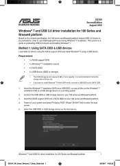
... install Windows® 7 64-bit UEFI mode, use USB keyboard/mouse during POST (Power-On Self Test) to a USB storage device on your 100 series and Braswell platform. 4. Insert the ASUS support DVD into a USB ODD, or copy all files on the Windows® 7 installation DVD to enter the boot screen. 5. Power on a working system. 2. DE164 Second Edition August 2015 Windows® 7 and USB 3.0 driver installation for 100 Series and Braswell platform DE164_100_Series_Windows_7_Setup_Guide.indd 1 1 2015/8/7 14:35:26 Connect the USB ODD or USB storage device to use...
... install Windows® 7 64-bit UEFI mode, use USB keyboard/mouse during POST (Power-On Self Test) to a USB storage device on your 100 series and Braswell platform. 4. Insert the ASUS support DVD into a USB ODD, or copy all files on the Windows® 7 installation DVD to enter the boot screen. 5. Power on a working system. 2. DE164 Second Edition August 2015 Windows® 7 and USB 3.0 driver installation for 100 Series and Braswell platform DE164_100_Series_Windows_7_Setup_Guide.indd 1 1 2015/8/7 14:35:26 Connect the USB ODD or USB storage device to use...
Win7 Installation guideEnglish
Page 2
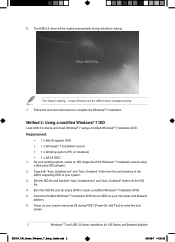
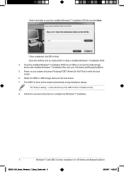
... of the ASUS supporting DVD to enter the boot screen. 2 Windows® 7 and USB 3.0 driver installation for 100 Series and Braswell platform DE164_100_Series_Windows_7_Setup_Guide.indd 2 2015/8/7 14:35:26 Insert the modified Windows® 7 installation DVD into the ISO file. 4. The USB 3.0 driver will show up if the USB 3.0 driver is starting..." Burn this ISO file onto an empty DVD to complete the Windows® 7 installation. 6. Method 2: Using a modified Windows® 7 ISO Load USB 3.0 drivers and install Windows® 7 using a third-party ISO software. 2.
... of the ASUS supporting DVD to enter the boot screen. 2 Windows® 7 and USB 3.0 driver installation for 100 Series and Braswell platform DE164_100_Series_Windows_7_Setup_Guide.indd 2 2015/8/7 14:35:26 Insert the modified Windows® 7 installation DVD into the ISO file. 4. The USB 3.0 driver will show up if the USB 3.0 driver is starting..." Burn this ISO file onto an empty DVD to complete the Windows® 7 installation. 6. Method 2: Using a modified Windows® 7 ISO Load USB 3.0 drivers and install Windows® 7 using a third-party ISO software. 2.
Win7 Installation guideEnglish
Page 3
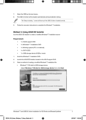
... file: • Windows® 7 OS disk to USB storage device then click Next. Select Windows 7 OS disk to USB storage device - Follow the onscreen instructions to create a modified Windows® 7 installation source Requirement: • 1 x ASUS support DVD • 1 x Windows® 7 installation DVD • 1 x Working system (PC or notebook) • 1 x SATA ODD • 1 x USB storage device (8 GB or more) 1. Select the ODD as the boot device. 8. Method 3: Using ASUS EZ Installer Use the ASUS EZ Installer to complete the Windows® 7 installation. 7. screen...
... file: • Windows® 7 OS disk to USB storage device then click Next. Select Windows 7 OS disk to USB storage device - Follow the onscreen instructions to create a modified Windows® 7 installation source Requirement: • 1 x ASUS support DVD • 1 x Windows® 7 installation DVD • 1 x Working system (PC or notebook) • 1 x SATA ODD • 1 x USB storage device (8 GB or more) 1. Select the ODD as the boot device. 8. Method 3: Using ASUS EZ Installer Use the ASUS EZ Installer to complete the Windows® 7 installation. 7. screen...
Win7 Installation guideEnglish
Page 6
... ISO file onto an empty DVD to complete the Windows® 7 installation. 6 Windows® 7 and USB 3.0 driver installation for 100 Series and Braswell platform DE164_100_Series_Windows_7_Setup_Guide.indd 6 2015/8/7 14:35:27 Select the ODD or USB storage device as the boot device. 7. Follow the onscreen instructions to create a modified Windows® 7 installation DVD. 4. Power on your 100 series and Braswell platform. 5. The USB 3.0 driver will show up if the USB 3.0 driver is starting..." The "Setup is loaded correctly...
... ISO file onto an empty DVD to complete the Windows® 7 installation. 6 Windows® 7 and USB 3.0 driver installation for 100 Series and Braswell platform DE164_100_Series_Windows_7_Setup_Guide.indd 6 2015/8/7 14:35:27 Select the ODD or USB storage device as the boot device. 7. Follow the onscreen instructions to create a modified Windows® 7 installation DVD. 4. Power on your 100 series and Braswell platform. 5. The USB 3.0 driver will show up if the USB 3.0 driver is starting..." The "Setup is loaded correctly...
Motherboard Pin Definition.English
Page 4
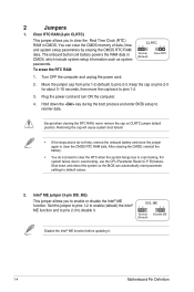
... (Default) Clear RTC 1. Keep the cap on CLRTC jumper default position. For system failure due to pins 2-3. Shut down the key during the boot process and enter BIOS setup to disable it . 1-4 Motherboard Pin Definition Set this jumper to pins 1-2 to enable (default) the Intel® ME function and to pins 2-3 to reenter data. The onboard button cell battery powers the RAM data in CMOS. Hold down and reboot the system so the BIOS can clear the CMOS memory of...
... (Default) Clear RTC 1. Keep the cap on CLRTC jumper default position. For system failure due to pins 2-3. Shut down the key during the boot process and enter BIOS setup to disable it . 1-4 Motherboard Pin Definition Set this jumper to pins 1-2 to enable (default) the Intel® ME function and to pins 2-3 to reenter data. The onboard button cell battery powers the RAM data in CMOS. Hold down and reboot the system so the BIOS can clear the CMOS memory of...

Motherboard Pin Definition.English
Page 5
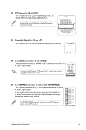
... power USBPWF mode) using the connected USB devices. Display panel backlight power selector (3-pin BLKT_PWR_SEL) BLKT_PWR_SEL 12 23 Pins 1-2 (Default) 2-3 Setting 12V 19V 12V 19V (Default) 6. Set to +5VSB to wake 12 23 up from S1 sleep mode (CPU stopped, DRAM refreshed, system running in the BIOS. 12 23 KB_USBPWB +5V +5VSB (Default) 5. LVDS panel/eDP selector (3-pin FPD_SEL) Pins 1-2 (Default) 2-3 Setting LVDS eDP VCC_PWR_SEL 1 3V (Default) 2 5V 3 12V FPD_SEL 12 23 for LVDS (Default) for each USB port; Keyboard and USB device wake up (3-pin...
... power USBPWF mode) using the connected USB devices. Display panel backlight power selector (3-pin BLKT_PWR_SEL) BLKT_PWR_SEL 12 23 Pins 1-2 (Default) 2-3 Setting 12V 19V 12V 19V (Default) 6. Set to +5VSB to wake 12 23 up from S1 sleep mode (CPU stopped, DRAM refreshed, system running in the BIOS. 12 23 KB_USBPWB +5V +5VSB (Default) 5. LVDS panel/eDP selector (3-pin FPD_SEL) Pins 1-2 (Default) 2-3 Setting LVDS eDP VCC_PWR_SEL 1 3V (Default) 2 5V 3 12V FPD_SEL 12 23 for LVDS (Default) for each USB port; Keyboard and USB device wake up (3-pin...
Motherboard Pin Definition.English
Page 6
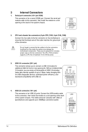
... USB 2.0 specifications and supports up to 480Mbps connection speed. Insufficient air flow inside the system may damage the motherboard components. Connect the serial port module cable to this connector, then install the module to the fan connectors. USB 2.0 connector (10-1 pin) This connector is for USB-chargeable devices, optimized power efficiency, and PIN 1 backward compatibility with USB 2.0. Connect the USB module cable USB to this connector, then install the module to a slot opening at the back of the connector CHA_FAN CPU FAN PWM CPU FAN IN CPU FAN...
... USB 2.0 specifications and supports up to 480Mbps connection speed. Insufficient air flow inside the system may damage the motherboard components. Connect the serial port module cable to this connector, then install the module to the fan connectors. USB 2.0 connector (10-1 pin) This connector is for USB-chargeable devices, optimized power efficiency, and PIN 1 backward compatibility with USB 2.0. Connect the USB module cable USB to this connector, then install the module to a slot opening at the back of the connector CHA_FAN CPU FAN PWM CPU FAN IN CPU FAN...
Motherboard Pin Definition.English
Page 9
... Storage Technology through the onboard Intel® chipset. SATA 6.0Gb/s connectors (7-pin SATA6G) These connectors connect to SATA 6.0 Gb/s hard disk drives via SATA 6.0 Gb/s signal cables. ODD_Lane3_P ODD_Lane3_N ODD_Lane2_P ODD_Lane2_N ODD_Lane1_P ODD_Lane1_N ODD_Lane0_P ODD_Lane0_N EVEN_Lane3_P EVEN_Lane3_N EVEN_Lane2_P EVEN_Lane2_N EVEN_Lane1_P EVEN_Lane1_N EVEN_Lane0_P EVEN_Lane0_N EDID_GND LCD_VCC LCD_VCC LCD_VCC Enable LVDS in the BIOS setup if the LVDS output is PIN 1 PIN 20 disabled by default. EDP(Back) PIN 1 14. SATA6G You must install Windows® XP Service...
... Storage Technology through the onboard Intel® chipset. SATA 6.0Gb/s connectors (7-pin SATA6G) These connectors connect to SATA 6.0 Gb/s hard disk drives via SATA 6.0 Gb/s signal cables. ODD_Lane3_P ODD_Lane3_N ODD_Lane2_P ODD_Lane2_N ODD_Lane1_P ODD_Lane1_N ODD_Lane0_P ODD_Lane0_N EVEN_Lane3_P EVEN_Lane3_N EVEN_Lane2_P EVEN_Lane2_N EVEN_Lane1_P EVEN_Lane1_N EVEN_Lane0_P EVEN_Lane0_N EDID_GND LCD_VCC LCD_VCC LCD_VCC Enable LVDS in the BIOS setup if the LVDS output is PIN 1 PIN 20 disabled by default. EDP(Back) PIN 1 14. SATA6G You must install Windows® XP Service...
Motherboard Pin Definition.English
Page 11
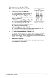
The system power LED lights up or flashes when data is for the system power button. Ground RESET NC PLED+ PLED- • Hard disk drive activity LED (2-pin +HDD_LED-) This 2-pin connector is for the HDD Activity LED. RESET +PWR_LED* Requires an ATX power supply • System warning speaker (4-pin SPEAKER) This 4-pin connector is for the chassis-mounted system warning speaker. Connect the chassis power LED cable to hear system beeps and warnings. • ATX power button/soft-off the system power. Pressing the power button turns the system on...
The system power LED lights up or flashes when data is for the system power button. Ground RESET NC PLED+ PLED- • Hard disk drive activity LED (2-pin +HDD_LED-) This 2-pin connector is for the HDD Activity LED. RESET +PWR_LED* Requires an ATX power supply • System warning speaker (4-pin SPEAKER) This 4-pin connector is for the chassis-mounted system warning speaker. Connect the chassis power LED cable to hear system beeps and warnings. • ATX power button/soft-off the system power. Pressing the power button turns the system on...
Motherboard Pin Definition.English
Page 12
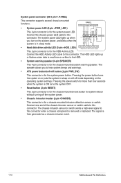
... reset button for system reboot without turning off mode depending on or puts the system in sleep mode. • Hard disk drive activity LED (2-pin +HDD_LED-) +HDD_LED- The chassis intrusion sensor or switch sends a high-level signal to this connector when a chassis component is then generated as a chassis intrusion event. 1-12 Motherboard Pin Definition The HDD LED lights up when PIN 1 CHASSIS HDD_LED+ HDD_LED- System panel connector (20-3 pin F_PANEL) This connector supports several chassis-mounted functions. • System power LED (4-pin +PWR_LED-) PANEL...
... reset button for system reboot without turning off mode depending on or puts the system in sleep mode. • Hard disk drive activity LED (2-pin +HDD_LED-) +HDD_LED- The chassis intrusion sensor or switch sends a high-level signal to this connector when a chassis component is then generated as a chassis intrusion event. 1-12 Motherboard Pin Definition The HDD LED lights up when PIN 1 CHASSIS HDD_LED+ HDD_LED- System panel connector (20-3 pin F_PANEL) This connector supports several chassis-mounted functions. • System power LED (4-pin +PWR_LED-) PANEL...
Intel 100 Series Ai Suite3 ManualEnglish
Page 14
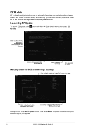
... updating BIOS and boot logo After you click or tap BIOS Update button, click or tap Flash to automatically update your system. 14 ASUS 100 Series AI Suite 3 Launching EZ Update To launch EZ Update, click on the left of the AI Suite 3 main menu, then select EZ Update. EZ Update EZ Update is a utility that allows you to update the BIOS and upload the boot logo in your motherboard's softwares, drivers and the BIOS version...
... updating BIOS and boot logo After you click or tap BIOS Update button, click or tap Flash to automatically update your system. 14 ASUS 100 Series AI Suite 3 Launching EZ Update To launch EZ Update, click on the left of the AI Suite 3 main menu, then select EZ Update. EZ Update EZ Update is a utility that allows you to update the BIOS and upload the boot logo in your motherboard's softwares, drivers and the BIOS version...
BIOSUpdateE-Manual English
Page 2
... repair, modification of such software and/or other Free Open Source Software Licenses. ASUSTeK is defaced or missing. No part of the product is eager to , by ASUS; or (2) the serial number of this manual, including the products and software described in it, may be distributed WITHOUT ANY WARRANTY and licensed under the same license as source code archives, etc. SPECIFICATIONS...
... repair, modification of such software and/or other Free Open Source Software Licenses. ASUSTeK is defaced or missing. No part of the product is eager to , by ASUS; or (2) the serial number of this manual, including the products and software described in it, may be distributed WITHOUT ANY WARRANTY and licensed under the same license as source code archives, etc. SPECIFICATIONS...
BIOSUpdateE-Manual English
Page 4
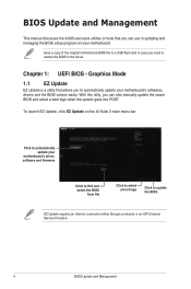
... BIOS from file Click to select a boot logo Click to restore the BIOS in case you need to update the BIOS EZ Update requires an Internet connection either through a network or an ISP (Internet Service Provider). 4 BIOS Update and Management BIOS Update and Management This manual discusses the ASUS-exclusive utilities or tools that allows you to automatically update your motherboard's softwares, drivers and the BIOS version easily. Save a copy of the original motherboard BIOS file to a USB flash disk...
... BIOS from file Click to select a boot logo Click to restore the BIOS in case you need to update the BIOS EZ Update requires an Internet connection either through a network or an ISP (Internet Service Provider). 4 BIOS Update and Management BIOS Update and Management This manual discusses the ASUS-exclusive utilities or tools that allows you to automatically update your motherboard's softwares, drivers and the BIOS version easily. Save a copy of the original motherboard BIOS file to a USB flash disk...
BIOSUpdateE-Manual English
Page 6
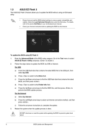
... update process is done. Via USB a) Insert the USB flash disk that you load the BIOS default settings to ensure system compatibility and stability. Enter the Advanced Mode of the BIOS setup program. 1.3 ASUS EZ Flash 3 The ASUS EZ Flash 3 feature allows you to update the BIOS without using EZ Flash 3: 1. Select the Load Optimized Defaults item under the Exit menu. To update the BIOS using an OS‑based utility. • Ensure that contains the latest BIOS file to the USB port...
... update process is done. Via USB a) Insert the USB flash disk that you load the BIOS default settings to ensure system compatibility and stability. Enter the Advanced Mode of the BIOS setup program. 1.3 ASUS EZ Flash 3 The ASUS EZ Flash 3 feature allows you to update the BIOS without using EZ Flash 3: 1. Select the Load Optimized Defaults item under the Exit menu. To update the BIOS using an OS‑based utility. • Ensure that contains the latest BIOS file to the USB port...

BIOSUpdateE-Manual English
Page 7
... or reset the system while updating the BIOS! You can cause system boot failure! BIOS Update and Management 7 The utility automatically checks the devices for the BIOS file. To ensure system compatibility and stability, we recommend that contains the updated BIOS file. • Before using the motherboard support DVD or a USB flash drive that you to enter BIOS Setup to recover BIOS settings. Turn on the system. 2. 1.4 ASUS CrashFree BIOS 3 The ASUS CrashFree BIOS 3 is an auto recovery tool that contains the BIOS file to the USB port. 3.
... or reset the system while updating the BIOS! You can cause system boot failure! BIOS Update and Management 7 The utility automatically checks the devices for the BIOS file. To ensure system compatibility and stability, we recommend that contains the updated BIOS file. • Before using the motherboard support DVD or a USB flash drive that you to enter BIOS Setup to recover BIOS settings. Turn on the system. 2. 1.4 ASUS CrashFree BIOS 3 The ASUS CrashFree BIOS 3 is an auto recovery tool that contains the BIOS file to the USB port. 3.
BIOSUpdateE-Manual English
Page 9
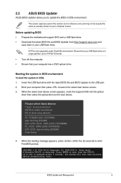
... device automatically. Press ENTER to enter FreeDOS prompt. ISOLINUX 3.20 2006-08-26 Copyright (C) 1994-2005 H. Before updating BIOS • Prepare the motherboard support DVD and a USB flash drive. • Download the latest BIOS file and BIOS Updater from the DVD/CD. Insert the USB flash drive with the latest BIOS file and BIOS Updater to boot using defaults P2: ST3808110AS (76319MB) aigo miniking (250MB) UEFI: (FAT) ASUS DRW-2014L1T(4458MB) P1: ASUS DRW-2014L1T(4458MB) UEFI: (FAT) aigo miniking (250MB) Enter Setup 4. Boot...
... device automatically. Press ENTER to enter FreeDOS prompt. ISOLINUX 3.20 2006-08-26 Copyright (C) 1994-2005 H. Before updating BIOS • Prepare the motherboard support DVD and a USB flash drive. • Download the latest BIOS file and BIOS Updater from the DVD/CD. Insert the USB flash drive with the latest BIOS file and BIOS Updater to boot using defaults P2: ST3808110AS (76319MB) aigo miniking (250MB) UEFI: (FAT) ASUS DRW-2014L1T(4458MB) P1: ASUS DRW-2014L1T(4458MB) UEFI: (FAT) aigo miniking (250MB) Enter Setup 4. Boot...

Users manual English
Page 2
... Software Licenses. If however you to Provide Source Code of shipment with you. Offer to the source code of these licenses are included in this product. SPECIFICATIONS AND INFORMATION CONTAINED IN THIS MANUAL ARE FURNISHED FOR INFORMATIONAL USE ONLY, AND ARE SUBJECT TO CHANGE AT ANY TIME WITHOUT NOTICE, AND SHOULD NOT BE CONSTRUED AS A COMMITMENT BY ASUS...
... Software Licenses. If however you to Provide Source Code of shipment with you. Offer to the source code of these licenses are included in this product. SPECIFICATIONS AND INFORMATION CONTAINED IN THIS MANUAL ARE FURNISHED FOR INFORMATIONAL USE ONLY, AND ARE SUBJECT TO CHANGE AT ANY TIME WITHOUT NOTICE, AND SHOULD NOT BE CONSTRUED AS A COMMITMENT BY ASUS...
Users manual English
Page 11
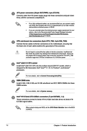
... wire of each cable matches the ground pin of the connector. Intel® LGA1151 CPU socket Install Intel® LGA1151 CPU into these connectors and push down firmly until the connectors completely fit. • For a fully configured system, we recommend that you are not jumpers! When using hot-plug and NCQ, set the SATA Mode Selection item in the BIOS to the fan connectors. ATX power connectors (24-pin EATXPWR, 4-pin ATX12V) Correctly orient the ATX power supply plugs...
... wire of each cable matches the ground pin of the connector. Intel® LGA1151 CPU socket Install Intel® LGA1151 CPU into these connectors and push down firmly until the connectors completely fit. • For a fully configured system, we recommend that you are not jumpers! When using hot-plug and NCQ, set the SATA Mode Selection item in the BIOS to the fan connectors. ATX power connectors (24-pin EATXPWR, 4-pin ATX12V) Correctly orient the ATX power supply plugs...
Users manual English
Page 13
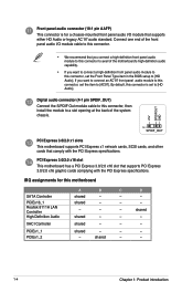
... is for this connector, set the Front Panel Type item in the BIOS setup to [HD Audio]. shared - - - - - - shared - - - - shared - - - By default, this connector to avail of the system chassis. +5V SPDIFOUT GND PIN 1 SPDIF_OUT PCI Express 3.0/2.0 x1 slots This motherboard supports PCI Express x1 network cards, SCSI cards, and other cards that comply with the PCI Express specifications. shared - - 1-4 Chapter 1: Product introduction PCI Express 3.0/2.0 x16 slot This motherboard has a PCI Express 3.0/2.0 x16 slot that supports either HD Audio or legacy AC`97...
... is for this connector, set the Front Panel Type item in the BIOS setup to [HD Audio]. shared - - - - - - shared - - - - shared - - - By default, this connector to avail of the system chassis. +5V SPDIFOUT GND PIN 1 SPDIF_OUT PCI Express 3.0/2.0 x1 slots This motherboard supports PCI Express x1 network cards, SCSI cards, and other cards that comply with the PCI Express specifications. shared - - 1-4 Chapter 1: Product introduction PCI Express 3.0/2.0 x16 slot This motherboard has a PCI Express 3.0/2.0 x16 slot that supports either HD Audio or legacy AC`97...
Users manual English
Page 18
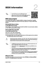
... during the Power-On Self Test (POST). BIOS information 2 • Scan the QR code to update the BIOS or configure its routines. Select the Load Optimized Defaults item under two modes: EZ Mode and Advanced Mode. BIOS setup program Use the BIOS Setup program to view the BIOS update guide. • Before using the ASUS CrashFree BIOS 3 utility, rename the BIOS file in this option only if you in using the first two options. The BIOS screens include navigation keys and brief...
... during the Power-On Self Test (POST). BIOS information 2 • Scan the QR code to update the BIOS or configure its routines. Select the Load Optimized Defaults item under two modes: EZ Mode and Advanced Mode. BIOS setup program Use the BIOS Setup program to view the BIOS update guide. • Before using the ASUS CrashFree BIOS 3 utility, rename the BIOS file in this option only if you in using the first two options. The BIOS screens include navigation keys and brief...


