
User Manual
Page 1
F1A75-V EVO Motherboard
F1A75-V EVO Motherboard
User Manual
Page 3
DIGI+ VRM 1-2 1.3.3 ASUS Digital Power Design 1-3 1.4 Before you proceed 1-6 1.5 Motherboard overview 1-7 1.5.1 Placement direction 1-7 1.5.2 Screw holes 1-7 1.5.3 Motherboard layout 1-8 1.5.4 Layout contents 1-8 1.6 Accelerated Processing Unit (APU 1-9 1.6.1 Installing the APU 1-9 1.6.2 Installing...1-19 iii Contents Notices...vi Safety information vii About this guide viii F1A75-V EVO specifications summary ix Chapter 1 Product introduction 1.1 Welcome 1-1 1.2 Package contents 1-1 1.3 Special features 1-1 1.3.1 Product highlights 1-1 1.3.2 Dual Intelligent ...
DIGI+ VRM 1-2 1.3.3 ASUS Digital Power Design 1-3 1.4 Before you proceed 1-6 1.5 Motherboard overview 1-7 1.5.1 Placement direction 1-7 1.5.2 Screw holes 1-7 1.5.3 Motherboard layout 1-8 1.5.4 Layout contents 1-8 1.6 Accelerated Processing Unit (APU 1-9 1.6.1 Installing the APU 1-9 1.6.2 Installing...1-19 iii Contents Notices...vi Safety information vii About this guide viii F1A75-V EVO specifications summary ix Chapter 1 Product introduction 1.1 Welcome 1-1 1.2 Package contents 1-1 1.3 Special features 1-1 1.3.1 Product highlights 1-1 1.3.2 Dual Intelligent ...
User Manual
Page 7
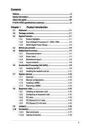
... we published the chemical substances in municipal waste. DO NOT throw the motherboard in our products at ASUS REACH website at http://csr.asus.com/english/REACH.htm. Operation safety • Before installing the motherboard and adding devices on a stable surface. • If you are ...qualified service technician or your dealer immediately. • To avoid short circuits, keep paper clips, screws, and staples away from the motherboard, ensure that all cables are correctly connected and the power cables are connected. If you are unplugged. • Seek professional assistance ...
... we published the chemical substances in municipal waste. DO NOT throw the motherboard in our products at ASUS REACH website at http://csr.asus.com/english/REACH.htm. Operation safety • Before installing the motherboard and adding devices on a stable surface. • If you are ...qualified service technician or your dealer immediately. • To avoid short circuits, keep paper clips, screws, and staples away from the motherboard, ensure that all cables are correctly connected and the power cables are connected. If you are unplugged. • Seek professional assistance ...
User Manual
Page 8
...this guide is organized This guide contains the following parts: • Chapter 1: Product introduction This chapter describes the features of the motherboard and the new technology it supports. • Chapter 2: BIOS information This chapter tells how to change system settings through the BIOS... sign means that you complete a task. NOTE: Tips and additional information to complete a task. ASUS websites The ASUS website provides updated information on ASUS hardware and software products. Detailed descriptions of the BIOS parameters are not part of the following sources ...
...this guide is organized This guide contains the following parts: • Chapter 1: Product introduction This chapter describes the features of the motherboard and the new technology it supports. • Chapter 2: BIOS information This chapter tells how to change system settings through the BIOS... sign means that you complete a task. NOTE: Tips and additional information to complete a task. ASUS websites The ASUS website provides updated information on ASUS hardware and software products. Detailed descriptions of the BIOS parameters are not part of the following sources ...
User Manual
Page 13
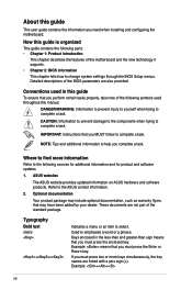
... package with the list below. 1.2 Package contents Check your motherboard package for buying an ASUS® F1A75-V EVO motherboard! Before you for the following items. Motherboard Cables Accessories Application DVD Documentations ASUS F1A75-V EVO motherboard 2 x Serial ATA 6.0Gb/s cables 1 x Q-Shield 1 x Q-Connector (retail version only) ASUS motherboard Support DVD User Manual If any of ASUS quality motherboards! Chapter 1 Product introduction 1.1 Welcome! It features Dual-channel...
... package with the list below. 1.2 Package contents Check your motherboard package for buying an ASUS® F1A75-V EVO motherboard! Before you for the following items. Motherboard Cables Accessories Application DVD Documentations ASUS F1A75-V EVO motherboard 2 x Serial ATA 6.0Gb/s cables 1 x Q-Shield 1 x Q-Connector (retail version only) ASUS motherboard Support DVD User Manual If any of ASUS quality motherboards! Chapter 1 Product introduction 1.1 Welcome! It features Dual-channel...
User Manual
Page 14
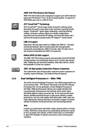
...1-2 Chapter 1: Product introduction DIGI+ VRM The world's first Dual Intelligent Processors from ASUS pioneered the use of current bus systems. 100% All High-quality Conductive Polymer Capacitors This motherboard uses all high-quality conductive polymer capacitors for fast, yet stable clock speeds, and...4 x USB 3.0 Ports. Native SATA 6.0 Gb/s support The AMD® A75 FCH natively supports next-generation Serial ATA (SATA) storage interface, this motherboard delivers up to 5GT/s interface speed and PCI Express™ 2.0 x 16 (at 4.8Gbps with USB 3.0 - It's the most precise power delivery ...
...1-2 Chapter 1: Product introduction DIGI+ VRM The world's first Dual Intelligent Processors from ASUS pioneered the use of current bus systems. 100% All High-quality Conductive Polymer Capacitors This motherboard uses all high-quality conductive polymer capacitors for fast, yet stable clock speeds, and...4 x USB 3.0 Ports. Native SATA 6.0 Gb/s support The AMD® A75 FCH natively supports next-generation Serial ATA (SATA) storage interface, this motherboard delivers up to 5GT/s interface speed and PCI Express™ 2.0 x 16 (at 4.8Gbps with USB 3.0 - It's the most precise power delivery ...
User Manual
Page 16
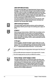
...Mode displays frequently-accessed setup info, while the Advanced Mode is for motherboard users, but also BC 1.1** standard mobile devices three times*** as fast as their operating system. This all the exclusive ASUS features into one software offers diverse and ease to use software package...more flexible and convenient mouse input. It natively supports hard drives larger than traditional BIOS versions. ASUS Anti-Surge Protection This special design protects expensive devices and the motherboard from damage caused by power surges from switching power supply unit (PSU). It allows you ...
...Mode displays frequently-accessed setup info, while the Advanced Mode is for motherboard users, but also BC 1.1** standard mobile devices three times*** as fast as their operating system. This all the exclusive ASUS features into one software offers diverse and ease to use software package...more flexible and convenient mouse input. It natively supports hard drives larger than traditional BIOS versions. ASUS Anti-Surge Protection This special design protects expensive devices and the motherboard from damage caused by power surges from switching power supply unit (PSU). It allows you ...
User Manual
Page 17
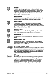
...friendly and energy-efficient products through product design and innovation to open the system chassis and clear the RTC data. ErP ready The motherboard is a user-friendly utility that allows you to update the BIOS without using the bundled support DVD or a USB flash disk...design speed up and simplify the DIY process! feature automatically restores the CPU default settings when the system hangs due to energy consumptions. ASUS F1A75-V EVO 1-5 ASUS MyLogo 2™ Turn your favorite photos into 256-color boot logos to personalize your DIY experience. Simply shut down and reboot the ...
...friendly and energy-efficient products through product design and innovation to open the system chassis and clear the RTC data. ErP ready The motherboard is a user-friendly utility that allows you to update the BIOS without using the bundled support DVD or a USB flash disk...design speed up and simplify the DIY process! feature automatically restores the CPU default settings when the system hangs due to energy consumptions. ASUS F1A75-V EVO 1-5 ASUS MyLogo 2™ Turn your favorite photos into 256-color boot logos to personalize your DIY experience. Simply shut down and reboot the ...
User Manual
Page 18
..., switch off the ATX power supply and detach its power cord. 1.4 Before you proceed Take note of the following precautions before you install motherboard components or change any motherboard settings. • Unplug the power cord from the wall socket before touching any component. • Before handling components, use a grounded wrist strap or... or a metal object, such as the power supply case, to avoid damaging them due to static electricity. • Hold components by the edges to the motherboard, peripherals, or components. 1-6 Chapter 1: Product introduction
..., switch off the ATX power supply and detach its power cord. 1.4 Before you proceed Take note of the following precautions before you install motherboard components or change any motherboard settings. • Unplug the power cord from the wall socket before touching any component. • Before handling components, use a grounded wrist strap or... or a metal object, such as the power supply case, to avoid damaging them due to static electricity. • Hold components by the edges to the motherboard, peripherals, or components. 1-6 Chapter 1: Product introduction
User Manual
Page 19
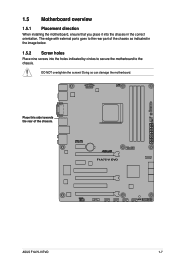
Doing so can damage the motherboard. F1A75-V EVO ASUS F1A75-V EVO 1-7 Place this side towards the rear of the chassis as indicated in the image below. 1.5.2 Screw holes Place nine screws into the chassis in the correct orientation. 1.5 Motherboard overview 1.5.1 Placement direction When installing the motherboard, ensure that you place it into the holes indicated by circles to secure the motherboard to the chassis. DO NOT overtighten the screws! The edge with external ports goes to the rear part of the chassis.
Doing so can damage the motherboard. F1A75-V EVO ASUS F1A75-V EVO 1-7 Place this side towards the rear of the chassis as indicated in the image below. 1.5.2 Screw holes Place nine screws into the chassis in the correct orientation. 1.5 Motherboard overview 1.5.1 Placement direction When installing the motherboard, ensure that you place it into the holes indicated by circles to secure the motherboard to the chassis. DO NOT overtighten the screws! The edge with external ports goes to the rear part of the chassis.
User Manual
Page 20
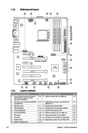
...) 1-26 17. Front panel audio connector (10-1 pin AAFP) 1-25 19. MemOK! Standby power LED (SB_PWR) 1-12 14. 1.5.3 Motherboard layout 1 2 13 4 24.4cm(9.6in) KB_USB3_34 SPDIFO _HDMI _DP ASM 1042 EATX12V DIGI+VRM EPU CPU_FAN SOCKET FM1 DVI_VGA ESATA6G _USB3_12 LAN1_USB12 DDR3... 7 8 MemOK! 9 10 1 2 30.5cm(12.0in) AUDIO PWR_FAN CHA_FAN1 PCIEX1_1 Lithium Cell CMOS Power RTL 8111E PCIEX16_1 PCIEX1_2 F1A75-V EVO USB3_56 EATXPWR 11 SATA6G_E1 12 SATA6G_1 SATA6G_3 SATA6G_5 SATA6G_2 SATA6G_4 SATA6G_6 ICS 477D Super I/O PCI1 AMD® A75 FCH 12 PCIEX16_2 TPU PCI2...
...) 1-26 17. Front panel audio connector (10-1 pin AAFP) 1-25 19. MemOK! Standby power LED (SB_PWR) 1-12 14. 1.5.3 Motherboard layout 1 2 13 4 24.4cm(9.6in) KB_USB3_34 SPDIFO _HDMI _DP ASM 1042 EATX12V DIGI+VRM EPU CPU_FAN SOCKET FM1 DVI_VGA ESATA6G _USB3_12 LAN1_USB12 DDR3... 7 8 MemOK! 9 10 1 2 30.5cm(12.0in) AUDIO PWR_FAN CHA_FAN1 PCIEX1_1 Lithium Cell CMOS Power RTL 8111E PCIEX16_1 PCIEX1_2 F1A75-V EVO USB3_56 EATXPWR 11 SATA6G_E1 12 SATA6G_1 SATA6G_3 SATA6G_5 SATA6G_2 SATA6G_4 SATA6G_6 ICS 477D Super I/O PCI1 AMD® A75 FCH 12 PCIEX16_2 TPU PCI2...
User Manual
Page 21
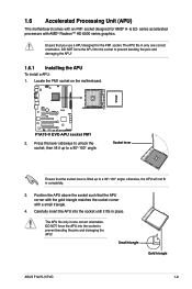
... triangle ASUS F1A75-V EVO 1-9 F1A75-V EVO F1A75-V EVO APU socket FM1 2. Socket lever Ensure that the APU corner with the gold triangle matches the socket corner with a small triangle. 4. series accelerated processors with an FM1 socket designed for the FM1 socket. Locate the FM1 socket on the motherboard. Press...place. DO NOT force the APU into the socket to a 90°-100° angle; 1.6 Accelerated Processing Unit (APU) This motherboard comes with AMD® Radeon™ HD 6000 series graphics. The APU fits only in completely. 3. Position the APU above the...
... triangle ASUS F1A75-V EVO 1-9 F1A75-V EVO F1A75-V EVO APU socket FM1 2. Socket lever Ensure that the APU corner with the gold triangle matches the socket corner with a small triangle. 4. series accelerated processors with an FM1 socket designed for the FM1 socket. Locate the FM1 socket on the motherboard. Press...place. DO NOT force the APU into the socket to a 90°-100° angle; 1.6 Accelerated Processing Unit (APU) This motherboard comes with AMD® Radeon™ HD 6000 series graphics. The APU fits only in completely. 3. Position the APU above the...
User Manual
Page 22
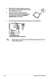
... is locked. 6. Install a APU heatsink and fan following the instructions that it is in place, push down the socket lever to plug this connector. CPU_FAN F1A75-V EVO F1A75-V EVO CPU fan connector DO NOT forget to indicate that comes with the heatsink package. CPU FAN PWM CPU FAN IN CPU FAN PWR GND 1-10... APU. Connect the CPU fan cable to the CPU_FAN connector on the side tab to connect the CPU fan connector! The lever clicks on the motherboard. 5.
... is locked. 6. Install a APU heatsink and fan following the instructions that it is in place, push down the socket lever to plug this connector. CPU_FAN F1A75-V EVO F1A75-V EVO CPU fan connector DO NOT forget to indicate that comes with the heatsink package. CPU FAN PWM CPU FAN IN CPU FAN PWR GND 1-10... APU. Connect the CPU fan cable to the CPU_FAN connector on the side tab to connect the CPU fan connector! The lever clicks on the motherboard. 5.
User Manual
Page 23
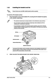
...If the instructions in this section do not have to remove the retention module base when installing the CPU or installing other motherboard components. • If you purchased a separate CPU heatsink and fan assembly, ensure that you install the heatsink and ...8226; The retention module base is properly applied to the retention module base. 1 2 3 4 5 ASUS F1A75-V EVO 1-11 1.6.2 Installing the heatsink and fan Ensure that a Thermal Interface Material is already installed on the motherboard upon purchase. • You do not match the CPU documentation, follow the latter. 2. CPU Fan...
...If the instructions in this section do not have to remove the retention module base when installing the CPU or installing other motherboard components. • If you purchased a separate CPU heatsink and fan assembly, ensure that you install the heatsink and ...8226; The retention module base is properly applied to the retention module base. 1 2 3 4 5 ASUS F1A75-V EVO 1-11 1.6.2 Installing the heatsink and fan Ensure that a Thermal Interface Material is already installed on the motherboard upon purchase. • You do not match the CPU documentation, follow the latter. 2. CPU Fan...

User Manual
Page 24
.... 1.7 System memory 1.7.1 Overview This motherboard comes with less power consumption. Align the other end of the DDR3 DIMM sockets: DIMM_A1 DIMM_A2 DIMM_B1 DIMM_B2 F1A75-V EVO Channel Channel A Channel B Sockets DIMM_A1 and DIMM_A2 DIMM_B1 and DIMM_B2 F1A75-V EVO 240-pin DDR3 DIMM sockets 1-12 ... the fan and heatsink assembly perfectly fits the retention mechanism module base, otherwise you fail to the connector on the motherboard labeled CPU_FAN. 3. Ensure that the retention bracket is notched differently to prevent installation on the retention mechanism to secure ...
.... 1.7 System memory 1.7.1 Overview This motherboard comes with less power consumption. Align the other end of the DDR3 DIMM sockets: DIMM_A1 DIMM_A2 DIMM_B1 DIMM_B2 F1A75-V EVO Channel Channel A Channel B Sockets DIMM_A1 and DIMM_A2 DIMM_B1 and DIMM_B2 F1A75-V EVO 240-pin DDR3 DIMM sockets 1-12 ... the fan and heatsink assembly perfectly fits the retention mechanism module base, otherwise you fail to the connector on the motherboard labeled CPU_FAN. 3. Ensure that the retention bracket is notched differently to prevent installation on the retention mechanism to secure ...
User Manual
Page 25
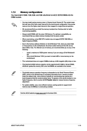
...: - For optimum compatibility, we recommend that you are available in Channel A and Channel B. For effective use a more memory on the motherboard, the actual usable memory for the dual-channel configuration. ASUS F1A75-V EVO 1-13 To operate at the vendor-marked or at a lower frequency than the vendor-marked value. Under the default state, some...
...: - For optimum compatibility, we recommend that you are available in Channel A and Channel B. For effective use a more memory on the motherboard, the actual usable memory for the dual-channel configuration. ASUS F1A75-V EVO 1-13 To operate at the vendor-marked or at a lower frequency than the vendor-marked value. Under the default state, some...
User Manual
Page 26
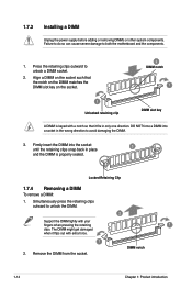
... the DIMM. 2 Support the DIMM lightly with extra force. 1 2. Locked Retaining Clip 1.7.4 Removing a DIMM To remove a DIMM: 1. Press the retaining clips outward to both the motherboard and the components. 1. Simultaneously press the retaining clips outward to avoid damaging the DIMM. 3. 1.7.3 Installing a DIMM Unplug the power supply before adding or removing DIMMs...
... the DIMM. 2 Support the DIMM lightly with extra force. 1 2. Locked Retaining Clip 1.7.4 Removing a DIMM To remove a DIMM: 1. Press the retaining clips outward to both the motherboard and the components. 1. Simultaneously press the retaining clips outward to avoid damaging the DIMM. 3. 1.7.3 Installing a DIMM Unplug the power supply before adding or removing DIMMs...
User Manual
Page 27
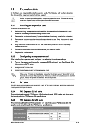
...removing expansion cards. Install the software drivers for single VGA card) x8 x16 PCIe x16_2 N/A x8 N/A PCIe x16_3 N/A N/A x4 ASUS F1A75-V EVO 1-15 VGA configuration Single VGA/PCIe card Dual VGA/PCIe card PCI Express operating mode PCIe x16_1 x16 (Recommended for the expansion card.... Express specifications. See Chapter 2 for the card. 2. 1.8 Expansion slots In the future, you may cause you physical injury and damage motherboard components. 1.8.1 Installing an expansion card To install an expansion card: 1. Remove the bracket opposite the slot that support PCI Express 2.0 x16...
...removing expansion cards. Install the software drivers for single VGA card) x8 x16 PCIe x16_2 N/A x8 N/A PCIe x16_3 N/A N/A x4 ASUS F1A75-V EVO 1-15 VGA configuration Single VGA/PCIe card Dual VGA/PCIe card PCI Express operating mode PCIe x16_1 x16 (Recommended for the expansion card.... Express specifications. See Chapter 2 for the card. 2. 1.8 Expansion slots In the future, you may cause you physical injury and damage motherboard components. 1.8.1 Installing an expansion card To install an expansion card: 1. Remove the bracket opposite the slot that support PCI Express 2.0 x16...
User Manual
Page 28
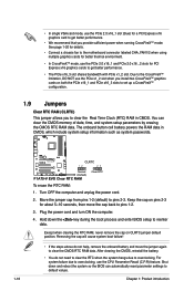
... slot when you provide sufficient power when running CrossFireX™ mode. See page 1-20 for details. • Connect a chassis fan to the motherboard connector labeled CHA_FAN1/2 when using multiple graphics cards for better thermal environment. • In CrossFireXTM mode, use the PCIe 2.0 x16_1 and PCIe 2.0...card to clear the Real Time Clock (RTC) RAM in CMOS, which include system setup information such as system passwords. F1A75-V EVO CLRTC 12 23 Normal (Default) F1A75-V EVO Clear RTC RAM Clear RTC To erase the RTC RAM: 1. Except when clearing the RTC RAM, never remove the cap...
... slot when you provide sufficient power when running CrossFireX™ mode. See page 1-20 for details. • Connect a chassis fan to the motherboard connector labeled CHA_FAN1/2 when using multiple graphics cards for better thermal environment. • In CrossFireXTM mode, use the PCIe 2.0 x16_1 and PCIe 2.0...card to clear the Real Time Clock (RTC) RAM in CMOS, which include system setup information such as system passwords. F1A75-V EVO CLRTC 12 23 Normal (Default) F1A75-V EVO Clear RTC RAM Clear RTC To erase the RTC RAM: 1. Except when clearing the RTC RAM, never remove the cap...
User Manual
Page 31
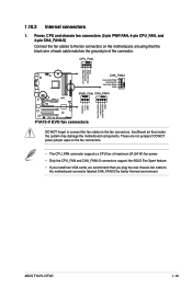
...ASUS F1A75-V EVO 1-19 CPU_FAN CPU FAN PWM CPU FAN IN CPU FAN PWR GND F1A75-V EVO CHA_FAN2 CHA FAN PWM CHA FAN IN CHA FAN PWR GND PWR_FAN CHA_FAN1 Rotation +12V GND CHA FAN PWM CHA FAN IN CHA FAN PWR GND F1A75-V EVO fan connectors DO NOT forget to connect the fan cables to the motherboard... connector labeled CHA_FAN1/2 for better thermal environment. DO NOT place jumper caps on the motherboard, ensuring that you install two VGA cards, we recommend that ...
...ASUS F1A75-V EVO 1-19 CPU_FAN CPU FAN PWM CPU FAN IN CPU FAN PWR GND F1A75-V EVO CHA_FAN2 CHA FAN PWM CHA FAN IN CHA FAN PWR GND PWR_FAN CHA_FAN1 Rotation +12V GND CHA FAN PWM CHA FAN IN CHA FAN PWR GND F1A75-V EVO fan connectors DO NOT forget to connect the fan cables to the motherboard... connector labeled CHA_FAN1/2 for better thermal environment. DO NOT place jumper caps on the motherboard, ensuring that you install two VGA cards, we recommend that ...


