
User Manual
Page 1
F1A75-M PRO Motherboard
F1A75-M PRO Motherboard

User Manual
Page 3
DIGI+ VRM 1-2 1.3.3 ASUS Digital Power Design 1-3 1.4 Before you proceed 1-6 1.5 Motherboard overview 1-7 1.5.1 Placement direction 1-7 1.5.2 Screw holes 1-7 1.5.3 Motherboard layout 1-8 1.5.4 Layout contents 1-8 1.6 Accelerated Processing Unit (APU 1-9 1.6.1 Installing the APU 1-9 1.6.2 Installing the ...Internal connectors 1-19 iii Contents Notices...vi Safety information vii About this guide viii F1A75-M PRO specifications summary ix Chapter 1: Product introduction 1.1 Welcome 1-1 1.2 Package contents 1-1 1.3 Special features 1-1 1.3.1 Product highlights 1-1 1.3.2 Dual Intelligent...
DIGI+ VRM 1-2 1.3.3 ASUS Digital Power Design 1-3 1.4 Before you proceed 1-6 1.5 Motherboard overview 1-7 1.5.1 Placement direction 1-7 1.5.2 Screw holes 1-7 1.5.3 Motherboard layout 1-8 1.5.4 Layout contents 1-8 1.6 Accelerated Processing Unit (APU 1-9 1.6.1 Installing the APU 1-9 1.6.2 Installing the ...Internal connectors 1-19 iii Contents Notices...vi Safety information vii About this guide viii F1A75-M PRO specifications summary ix Chapter 1: Product introduction 1.1 Welcome 1-1 1.2 Package contents 1-1 1.3 Special features 1-1 1.3.1 Product highlights 1-1 1.3.2 Dual Intelligent...

User Manual
Page 7
... damage, contact your dealer immediately. • To avoid short circuits, keep paper clips, screws, and staples away from the motherboard, ensure that all cables are correctly connected and the power cables are using the product, ensure that the power cables for disposal...Ensure that the product (electrical and electronic equipment) should not be placed in our products at ASUS REACH website at http://csr.asus.com/english/REACH.htm. Operation safety • Before installing the motherboard and adding devices on a stable surface. • If you encounter technical problems with the...
... damage, contact your dealer immediately. • To avoid short circuits, keep paper clips, screws, and staples away from the motherboard, ensure that all cables are correctly connected and the power cables are using the product, ensure that the power cables for disposal...Ensure that the product (electrical and electronic equipment) should not be placed in our products at ASUS REACH website at http://csr.asus.com/english/REACH.htm. Operation safety • Before installing the motherboard and adding devices on a stable surface. • If you encounter technical problems with the...

User Manual
Page 8
How this guide This user guide contains the information you complete a task. ASUS websites The ASUS website provides updated information on ASUS hardware and software products. Typography Bold text Italics ++ Indicates a menu or an item to help you need when installing and configuring the motherboard. Example: means that you MUST follow to complete a task. NOTE...
How this guide This user guide contains the information you complete a task. ASUS websites The ASUS website provides updated information on ASUS hardware and software products. Typography Bold text Italics ++ Indicates a menu or an item to help you need when installing and configuring the motherboard. Example: means that you MUST follow to complete a task. NOTE...

User Manual
Page 13
... A- & E2- Before you for the following items. Motherboard Cables Accessories Application DVD Documentations ASUS F1A75-M PRO motherboard 2 x Serial ATA 6.0Gb/s cables 1 x Q-Shield ASUS motherboard Support DVD User Manual If any of ASUS quality motherboards! It features Dual-channel DDR3 memory support and accelerates data ...transfer rate up to enable accelerated performance and an industry-leading visual experience. ASUS F1A75-M PRO 1-1 Thank you start installing the motherboard, and hardware devices on it another standout in one small, energy-efficient design to...
... A- & E2- Before you for the following items. Motherboard Cables Accessories Application DVD Documentations ASUS F1A75-M PRO motherboard 2 x Serial ATA 6.0Gb/s cables 1 x Q-Shield ASUS motherboard Support DVD User Manual If any of ASUS quality motherboards! It features Dual-channel DDR3 memory support and accelerates data ...transfer rate up to enable accelerated performance and an industry-leading visual experience. ASUS F1A75-M PRO 1-1 Thank you start installing the motherboard, and hardware devices on it another standout in one small, energy-efficient design to...

User Manual
Page 14
...2.0 components. Native SATA 6.0 Gb/s support The AMD® A75 FCH natively supports next-generation Serial ATA (SATA) storage interface, this motherboard delivers up to 5GT/s interface speed and PCI Express™ 2.0 x 16 (at 4.8Gbps with a programmable microprocessor that perfectly serves power...'s the most precise power delivery available providing the best in class power efficiency, greater performance, and rock solid stability. With ASUS DIGI+ VRM, users can automatically optimize the system for durability, improved lifespan, and enhanced thermal capacity. TPU Unleash your display...
...2.0 components. Native SATA 6.0 Gb/s support The AMD® A75 FCH natively supports next-generation Serial ATA (SATA) storage interface, this motherboard delivers up to 5GT/s interface speed and PCI Express™ 2.0 x 16 (at 4.8Gbps with a programmable microprocessor that perfectly serves power...'s the most precise power delivery available providing the best in class power efficiency, greater performance, and rock solid stability. With ASUS DIGI+ VRM, users can automatically optimize the system for durability, improved lifespan, and enhanced thermal capacity. TPU Unleash your display...

User Manual
Page 16
...diverse and ease to use software package. The exclusive EZ Mode displays frequently-accessed setup info, while the Advanced Mode is for motherboard users, but also BC 1.1** standard mobile devices three times*** as fast as their operating system. Not only the beautiful shape upgrades...extremely silent and cooling experience with no need to switch back and forth between different utilities. ASUS Anti-Surge Protection This special design protects expensive devices and the motherboard from damage caused by power surges from switching power supply unit (PSU). It natively supports hard...
...diverse and ease to use software package. The exclusive EZ Mode displays frequently-accessed setup info, while the Advanced Mode is for motherboard users, but also BC 1.1** standard mobile devices three times*** as fast as their operating system. Not only the beautiful shape upgrades...extremely silent and cooling experience with no need to switch back and forth between different utilities. ASUS Anti-Surge Protection This special design protects expensive devices and the motherboard from damage caused by power surges from switching power supply unit (PSU). It natively supports hard...

User Manual
Page 17
... controls of Q-LED, Q-Slot and Q-Code design speed up and simplify the DIY process! With better electric conductivity, it ideally protects your motherboard against Electronic Magnetic Interference (EMI). ASUS F1A75-M PRO 1-5 ASUS Q-Shield ASUS Q-Shield's special design makes it against static electricity and shields it convenient and easy to install on your PC's loading. C.P.R. Simply shut...
... controls of Q-LED, Q-Slot and Q-Code design speed up and simplify the DIY process! With better electric conductivity, it ideally protects your motherboard against Electronic Magnetic Interference (EMI). ASUS F1A75-M PRO 1-5 ASUS Q-Shield ASUS Q-Shield's special design makes it against static electricity and shields it convenient and easy to install on your PC's loading. C.P.R. Simply shut...

User Manual
Page 18
... you uninstall any component, place it on a grounded antistatic pad or in the bag that came with the component. • Before you install motherboard components or change any motherboard settings. • Unplug the power cord from the wall socket before touching any component, switch off the ATX power supply and detach its... do so may cause severe damage to avoid touching the ICs on them due to static electricity. • Hold components by the edges to the motherboard, peripherals, or components. 1-6 Chapter 1: Product introduction
... you uninstall any component, place it on a grounded antistatic pad or in the bag that came with the component. • Before you install motherboard components or change any motherboard settings. • Unplug the power cord from the wall socket before touching any component, switch off the ATX power supply and detach its... do so may cause severe damage to avoid touching the ICs on them due to static electricity. • Hold components by the edges to the motherboard, peripherals, or components. 1-6 Chapter 1: Product introduction

User Manual
Page 19
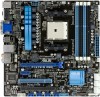
Place this side towards the rear of the chassis as indicated in the image below. 1.5.2 Screw holes Place eight screws into the chassis in the correct orientation. The edge with external ports goes to the rear part of the chassis. DO NOT overtighten the screws! F1A75-M PRO ASUS F1A75-M PRO 1-7 Doing so can damage the motherboard. 1.5 Motherboard overview 1.5.1 Placement direction When installing the motherboard, ensure that you place it into the holes indicated by circles to secure the motherboard to the chassis.
Place this side towards the rear of the chassis as indicated in the image below. 1.5.2 Screw holes Place eight screws into the chassis in the correct orientation. The edge with external ports goes to the rear part of the chassis. DO NOT overtighten the screws! F1A75-M PRO ASUS F1A75-M PRO 1-7 Doing so can damage the motherboard. 1.5 Motherboard overview 1.5.1 Placement direction When installing the motherboard, ensure that you place it into the holes indicated by circles to secure the motherboard to the chassis.

User Manual
Page 20
..., 8-pin EATX12V) 3. EPU LED (ELED740) 7. EPU switch 8. MemOK! Digital audio connector (4-1 pin SPDIF_OUT) 1-25 19. 1.5.3 Motherboard layout 1 2 13 24.4cm(9.6in) KB_USB3_34 SPDIF_O2 _HDMI ASM 1042 EATX12V DIGI+VRM EPU CPU_FAN SOCKET FM1 DVI_VGA USB3_12 LAN1_USB12 DDR3 DIMM_A1 ...7 8 9 10 2 EATXPWR CHA_FAN2 24.4cm(9.6in) CHA_FAN1 ICS477D AUDIO RTL 8111E Super I/O PWR_FAN Lithium Cell CMOS Power PCIEX16_1 F1A75-M PRO PCIEX1_1 TPU PCI1 AMD® A75 1 SB_PWR 11 12 SATA6G_2 SATA6G_4 SATA6G_6 SATA6G_1 SATA6G_3 SATA6G_5 ALC 892 AAFP SPDIF_OUT PCIEX16_2 USB78 COM1 ...
..., 8-pin EATX12V) 3. EPU LED (ELED740) 7. EPU switch 8. MemOK! Digital audio connector (4-1 pin SPDIF_OUT) 1-25 19. 1.5.3 Motherboard layout 1 2 13 24.4cm(9.6in) KB_USB3_34 SPDIF_O2 _HDMI ASM 1042 EATX12V DIGI+VRM EPU CPU_FAN SOCKET FM1 DVI_VGA USB3_12 LAN1_USB12 DDR3 DIMM_A1 ...7 8 9 10 2 EATXPWR CHA_FAN2 24.4cm(9.6in) CHA_FAN1 ICS477D AUDIO RTL 8111E Super I/O PWR_FAN Lithium Cell CMOS Power PCIEX16_1 F1A75-M PRO PCIEX1_1 TPU PCI1 AMD® A75 1 SB_PWR 11 12 SATA6G_2 SATA6G_4 SATA6G_6 SATA6G_1 SATA6G_3 SATA6G_5 ALC 892 AAFP SPDIF_OUT PCIEX16_2 USB78 COM1 ...

User Manual
Page 21
... is lifted up to prevent bending the pins and damaging the APU! 1.6.1 Installing the APU To install a APU: 1. F1A75-M PRO F1A75-M PRO processor socket FM1 2. Small triangle Gold triangle ASUS F1A75-M PRO 1-9 DO NOT force the APU into the socket to unlock the socket, then lift it fits in completely. 3. Press...° angle; DO NOT force the APU into the socket to a 90°-100° angle. Locate the FM1 socket on the motherboard. otherwise, the APU will not fit in place. The APU fits only in only one correct orientation. The APU fits in one correct orientation...
... is lifted up to prevent bending the pins and damaging the APU! 1.6.1 Installing the APU To install a APU: 1. F1A75-M PRO F1A75-M PRO processor socket FM1 2. Small triangle Gold triangle ASUS F1A75-M PRO 1-9 DO NOT force the APU into the socket to unlock the socket, then lift it fits in completely. 3. Press...° angle; DO NOT force the APU into the socket to a 90°-100° angle. Locate the FM1 socket on the motherboard. otherwise, the APU will not fit in place. The APU fits only in only one correct orientation. The APU fits in one correct orientation...

User Manual
Page 22
..., push down the socket lever to plug this connector. When the APU is locked. 6. You can occur if you fail to secure the APU. CPU_FAN F1A75-M PRO F1A75-M PRO CPU fan connector DO NOT forget to the CPU_FAN connector on the side tab to section 1.6.2 Installing heatsink and fan for instructions. 7. CPU FAN PWM... to connect the CPU fan connector! Hardware monitoring errors can also refer to indicate that comes with the heatsink package. The lever clicks on the motherboard.
..., push down the socket lever to plug this connector. When the APU is locked. 6. You can occur if you fail to secure the APU. CPU_FAN F1A75-M PRO F1A75-M PRO CPU fan connector DO NOT forget to the CPU_FAN connector on the side tab to section 1.6.2 Installing heatsink and fan for instructions. 7. CPU FAN PWM... to connect the CPU fan connector! Hardware monitoring errors can also refer to indicate that comes with the heatsink package. The lever clicks on the motherboard.

User Manual
Page 23
... to the retention module base. 1 2 3 4 5 ASUS F1A75-M PRO 1-11 Attach one end of the installed CPU, ensuring that the heatsink fits properly on the retention module base. • The retention module base is already installed on the motherboard upon purchase. • You do not match the CPU ...latter. 2. If the instructions in this section do not have to remove the retention module base when installing the CPU or installing other motherboard components. • If you purchased a separate CPU heatsink and fan assembly, ensure that you install the heatsink and fan assembly. 1.6.2 ...
... to the retention module base. 1 2 3 4 5 ASUS F1A75-M PRO 1-11 Attach one end of the installed CPU, ensuring that the heatsink fits properly on the retention module base. • The retention module base is already installed on the motherboard upon purchase. • You do not match the CPU ...latter. 2. If the instructions in this section do not have to remove the retention module base when installing the CPU or installing other motherboard components. • If you purchased a separate CPU heatsink and fan assembly, ensure that you install the heatsink and fan assembly. 1.6.2 ...

User Manual
Page 24
Align the other end of the DDR3 DIMM sockets: DIMM_A1 DIMM_A2 DIMM_B1 DIMM_B2 F1A75-M PRO Channel Channel A Channel B F1A75-M PRO 240-pin DDR3 DIMM sockets Sockets DIMM_A1 and DIMM_A2 DIMM_B1 and DIMM_B2 1-12 Chapter 1: Product introduction DO NOT forget to...clicking sound denotes that the fan and heatsink assembly perfectly fits the retention mechanism module base, otherwise you fail to prevent installation on the motherboard labeled CPU_FAN. A DDR3 module has the same physical dimensions as a DDR2 DIMM but is notched differently to plug this connector. 1.7 System memory...
Align the other end of the DDR3 DIMM sockets: DIMM_A1 DIMM_A2 DIMM_B1 DIMM_B2 F1A75-M PRO Channel Channel A Channel B F1A75-M PRO 240-pin DDR3 DIMM sockets Sockets DIMM_A1 and DIMM_A2 DIMM_B1 and DIMM_B2 1-12 Chapter 1: Product introduction DO NOT forget to...clicking sound denotes that the fan and heatsink assembly perfectly fits the retention mechanism module base, otherwise you fail to prevent installation on the motherboard labeled CPU_FAN. A DDR3 module has the same physical dimensions as a DDR2 DIMM but is notched differently to plug this connector. 1.7 System memory...

User Manual
Page 25
... Use a 64-bit Windows® OS if you want to install 4GB or more memory on the motherboard. • This motherboard does not support DIMMs made up of accessing information from the same vendor. • When overclocking, some... from the blue slots for better overclocking capability. • Always install DIMMs with 16GB or above DIMMs. ASUS will update the memory QVL once the DIMMs are using a 32-bit Windows® OS. - Under ... OS, when you install 4GB or more memory on the motherboard, the actual usable memory for the OS can be about 3GB or less. ASUS F1A75-M PRO 1-13
... Use a 64-bit Windows® OS if you want to install 4GB or more memory on the motherboard. • This motherboard does not support DIMMs made up of accessing information from the same vendor. • When overclocking, some... from the blue slots for better overclocking capability. • Always install DIMMs with 16GB or above DIMMs. ASUS will update the memory QVL once the DIMMs are using a 32-bit Windows® OS. - Under ... OS, when you install 4GB or more memory on the motherboard, the actual usable memory for the OS can be about 3GB or less. ASUS F1A75-M PRO 1-13

User Manual
Page 26
Press the retaining clips outward to both the motherboard and the components. 1. Locked Retaining Clip 1.7.4 Removing a DIMM To remove a DIMM: 1. Firmly insert the DIMM into a socket in the wrong direction to unlock the DIMM. 2 ...
Press the retaining clips outward to both the motherboard and the components. 1. Locked Retaining Clip 1.7.4 Removing a DIMM To remove a DIMM: 1. Firmly insert the DIMM into a socket in the wrong direction to unlock the DIMM. 2 ...

User Manual
Page 27
... with the slot and press firmly until the card is already installed in a chassis). 3. ASUS F1A75-M PRO 1-15 Install the software drivers for information on the slot. 5. 1.8 Expansion slots In the future, you may cause you physical injury and damage motherboard components. 1.8.1 Installing an expansion card To install an expansion card: 1. The following sub...
... with the slot and press firmly until the card is already installed in a chassis). 3. ASUS F1A75-M PRO 1-15 Install the software drivers for information on the slot. 5. 1.8 Expansion slots In the future, you may cause you physical injury and damage motherboard components. 1.8.1 Installing an expansion card To install an expansion card: 1. The following sub...

User Manual
Page 28
... (blue) for a PCI Express x16 graphics card to get better performance. • We recommend that you to pins 1-2. 3. F1A75-M PRO CLRTC 12 23 Normal (Default) F1A75-M PRO Clear RTC RAM Clear RTC To erase the RTC RAM: 1. After clearing the CMOS, reinstall the battery. • You do ... VGA card mode, use the CPU Parameter Recall (C.P.R) feature. See page 1-20 for details. • Connect a chassis fan to the motherboard connector labeled CHA_FAN1/2 when using multiple graphics cards for about 5~10 seconds, then move the jumper again to overclocking. You can automatically reset ...
... (blue) for a PCI Express x16 graphics card to get better performance. • We recommend that you to pins 1-2. 3. F1A75-M PRO CLRTC 12 23 Normal (Default) F1A75-M PRO Clear RTC RAM Clear RTC To erase the RTC RAM: 1. After clearing the CMOS, reinstall the battery. • You do ... VGA card mode, use the CPU Parameter Recall (C.P.R) feature. See page 1-20 for details. • Connect a chassis fan to the motherboard connector labeled CHA_FAN1/2 when using multiple graphics cards for about 5~10 seconds, then move the jumper again to overclocking. You can automatically reset ...

User Manual
Page 31
... IN CHA FAN PWR GND GND CHA FAN PWR CHA FAN IN CHA FAN PWM F1A75-M PRO PWR_FAN GND +12V Rotation F1A75-M PRO Fan connectors DO NOT forget to connect the fan cables to the motherboard connector labeled CHA_FAN1/2 for better thermal environment. Insufficient air flow inside the system may ...damage the motherboard components. DO NOT place jumper caps on the motherboard, ensuring that the black wire of each cable matches the ground pin of maximum 2A (24 W) fan power. • Only the CPU_FAN and CHA_FAN1/2 connectors support the ASUS Fan Xpert feature. • If...
... IN CHA FAN PWR GND GND CHA FAN PWR CHA FAN IN CHA FAN PWM F1A75-M PRO PWR_FAN GND +12V Rotation F1A75-M PRO Fan connectors DO NOT forget to connect the fan cables to the motherboard connector labeled CHA_FAN1/2 for better thermal environment. Insufficient air flow inside the system may ...damage the motherboard components. DO NOT place jumper caps on the motherboard, ensuring that the black wire of each cable matches the ground pin of maximum 2A (24 W) fan power. • Only the CPU_FAN and CHA_FAN1/2 connectors support the ASUS Fan Xpert feature. • If...


