User Manual
Page 13
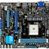
...the list below. 1.2 Package contents Check your retailer. 1.3 1.3.1 Special features Product highlights AMD® A- & E2- ASUS F1A75-M LE 1-1 It features Dual-channel DDR3 memory support and accelerates data transfer rate up to enable accelerated performance and an industry-leading...you for the following items. Motherboard Cables Accessories Application DVD Documentations ASUS F1A75-M LE motherboard 2 x Serial ATA 6.0Gb/s cables 1 x I/O shield ASUS motherboard Support DVD User Manual If any of ASUS quality motherboards! series accelerated processor with AMD® Radeon™ ...
...the list below. 1.2 Package contents Check your retailer. 1.3 1.3.1 Special features Product highlights AMD® A- & E2- ASUS F1A75-M LE 1-1 It features Dual-channel DDR3 memory support and accelerates data transfer rate up to enable accelerated performance and an industry-leading...you for the following items. Motherboard Cables Accessories Application DVD Documentations ASUS F1A75-M LE motherboard 2 x Serial ATA 6.0Gb/s cables 1 x I/O shield ASUS motherboard Support DVD User Manual If any of ASUS quality motherboards! series accelerated processor with AMD® Radeon™ ...
User Manual
Page 15
...BIOS file using a bootable floppy disk or an OS-based utility. ASUS MyLogo 2™ Turn your favorite photos into one software offers diverse and ease to use software package. C.P.R. ASUS F1A75-M LE 1-3 Moreover, the ASUS OC profiles in different geographic regions and your system. The built-in ...overclocking failure. settings in variety of useful profiles offer flexible controls of real-time OC-now a reality with the ASUS TurboV. ASUS EZ Flash 2 ASUS EZ Flash 2 is an auto-recovery tool that contains the BIOS file. feature automatically restores the CPU default ...
...BIOS file using a bootable floppy disk or an OS-based utility. ASUS MyLogo 2™ Turn your favorite photos into one software offers diverse and ease to use software package. C.P.R. ASUS F1A75-M LE 1-3 Moreover, the ASUS OC profiles in different geographic regions and your system. The built-in ...overclocking failure. settings in variety of useful profiles offer flexible controls of real-time OC-now a reality with the ASUS TurboV. ASUS EZ Flash 2 ASUS EZ Flash 2 is an auto-recovery tool that contains the BIOS file. feature automatically restores the CPU default ...
User Manual
Page 17
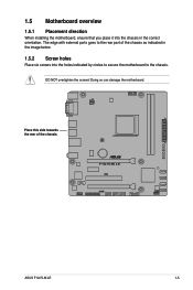
The edge with external ports goes to the chassis. ASUS F1A75-M LE 1-5 DO NOT overtighten the screws! Doing so can damage the motherboard. 1.5 Motherboard overview 1.5.1 Placement direction When installing the motherboard, ensure that you place it into the chassis in the image below. 1.5.2 Screw holes Place six screws into the holes indicated by circles to secure the motherboard to the rear part of the chassis. Place this side towards the rear of the chassis as indicated in the correct orientation.
The edge with external ports goes to the chassis. ASUS F1A75-M LE 1-5 DO NOT overtighten the screws! Doing so can damage the motherboard. 1.5 Motherboard overview 1.5.1 Placement direction When installing the motherboard, ensure that you place it into the chassis in the image below. 1.5.2 Screw holes Place six screws into the holes indicated by circles to secure the motherboard to the rear part of the chassis. Place this side towards the rear of the chassis as indicated in the correct orientation.
User Manual
Page 19
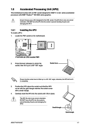
... damaging the APU! Socket lever Ensure that the APU corner with the gold triangle matches the socket corner with a small triangle. 4. Small triangle Gold triangle ASUS F1A75-M LE 1-7 DO NOT force the APU into the socket to prevent bending the pins and damaging the APU! 1.6.1 Installing the APU To install a APU: 1. The APU...
... damaging the APU! Socket lever Ensure that the APU corner with the gold triangle matches the socket corner with a small triangle. 4. Small triangle Gold triangle ASUS F1A75-M LE 1-7 DO NOT force the APU into the socket to prevent bending the pins and damaging the APU! 1.6.1 Installing the APU To install a APU: 1. The APU...
User Manual
Page 21
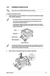
... assembly, ensure that the heatsink fits properly on the retention module base. • The retention module base is properly applied to the retention module base. 1 2 3 4 5 ASUS F1A75-M LE 1-9
... assembly, ensure that the heatsink fits properly on the retention module base. • The retention module base is properly applied to the retention module base. 1 2 3 4 5 ASUS F1A75-M LE 1-9

User Manual
Page 23
...QVL once the DIMMs are using a 32-bit Windows® OS. - Any excess memory from the blue slots for the dual-channel configuration. ASUS F1A75-M LE 1-11 Install a maximum of accessing information from the same vendor. • When overclocking, some memory modules for overclocking may not support DDR3 ...usable memory for the latest memory modules' Qualified Vendors List (QVL). Under the default state, some AMD CPU models may operate at www.asus.com for the OS can be supported with the same CAS latency. To operate at the vendor-marked or at a higher frequency, refer...
...QVL once the DIMMs are using a 32-bit Windows® OS. - Any excess memory from the blue slots for the dual-channel configuration. ASUS F1A75-M LE 1-11 Install a maximum of accessing information from the same vendor. • When overclocking, some memory modules for overclocking may not support DDR3 ...usable memory for the latest memory modules' Qualified Vendors List (QVL). Under the default state, some AMD CPU models may operate at www.asus.com for the OS can be supported with the same CAS latency. To operate at the vendor-marked or at a higher frequency, refer...
User Manual
Page 25
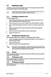
... card. 3. Replace the system cover. 1.8.2 Configuring an expansion card After installing the expansion card, configure it and make the necessary hardware settings for later use . ASUS F1A75-M LE 1-13
... card. 3. Replace the system cover. 1.8.2 Configuring an expansion card After installing the expansion card, configure it and make the necessary hardware settings for later use . ASUS F1A75-M LE 1-13
User Manual
Page 27
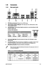
... Speaker Out Mic In Center/Subwoofer Rear Speaker Out - 8-channel Line In Front Speaker Out Mic In Center/Subwoofer Rear Speaker Out Side Speaker Out ASUS F1A75-M LE 1-15 Video Graphics Adapter (VGA) port. This port connects to the tape, CD, DVD player, or other VGA-compatible devices. 3. Microphone port (pink...
... Speaker Out Mic In Center/Subwoofer Rear Speaker Out - 8-channel Line In Front Speaker Out Mic In Center/Subwoofer Rear Speaker Out Side Speaker Out ASUS F1A75-M LE 1-15 Video Graphics Adapter (VGA) port. This port connects to the tape, CD, DVD player, or other VGA-compatible devices. 3. Microphone port (pink...
User Manual
Page 29
... you plug the rear chassis fan cable to the fan connectors on the fan connectors. • The CPU_FAN connector supports a CPU fan of the connector. ASUS F1A75-M LE 1-17 DO NOT place jumper caps on the motherboard, ensuring that the black wire of each cable matches the ground pin of maximum 2A (24... W) fan power. • Only the CPU_FAN and CHA_FAN connectors support the ASUS Fan Xpert feature. • If you install two VGA cards, we recommend that you to the fan connectors.
... you plug the rear chassis fan cable to the fan connectors on the fan connectors. • The CPU_FAN connector supports a CPU fan of the connector. ASUS F1A75-M LE 1-17 DO NOT place jumper caps on the motherboard, ensuring that the black wire of each cable matches the ground pin of maximum 2A (24... W) fan power. • Only the CPU_FAN and CHA_FAN connectors support the ASUS Fan Xpert feature. • If you install two VGA cards, we recommend that you to the fan connectors.
User Manual
Page 31
ASUS F1A75-M LE 1-19 If you can create a RAID 0, RAID 1, RAID 10, or JBOD configuration through the onboard controller. • These connectors are set to IDE mode by ...
ASUS F1A75-M LE 1-19 If you can create a RAID 0, RAID 1, RAID 10, or JBOD configuration through the onboard controller. • These connectors are set to IDE mode by ...

User Manual
Page 33
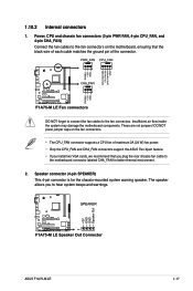
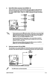
...; If you connect a high-definition front panel audio module to this connector, set the Front Panel Type item in the BIOS to configure the setting. 8. ASUS F1A75-M LE 1-21 The S/PDIF module is for an additional Sony/Philips Digital Interface (S/PDIF) port. See section 2.5.5 Onboard Devices Configuration for a chassis-mounted front panel audio...
...; If you connect a high-definition front panel audio module to this connector, set the Front Panel Type item in the BIOS to configure the setting. 8. ASUS F1A75-M LE 1-21 The S/PDIF module is for an additional Sony/Philips Digital Interface (S/PDIF) port. See section 2.5.5 Onboard Devices Configuration for a chassis-mounted front panel audio...
User Manual
Page 35
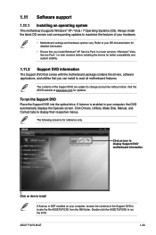
... contains the drivers, software applications, and utilities that you can install to run the Support DVD Place the Support DVD into the optical drive. ASUS F1A75-M LE 1-23 Visit the ASUS website at any time without notice. Double-click the ASSETUP.EXE to avail all motherboard features. Refer to your hardware. • Motherboard settings...1.11.1 Installing an operating system This motherboard supports Windows® XP / Vista / 7 Operating Systems (OS). The contents of the Support DVD to change at www.asus.com for reference only. To run the DVD. If Autorun is for updates.
... contains the drivers, software applications, and utilities that you can install to run the Support DVD Place the Support DVD into the optical drive. ASUS F1A75-M LE 1-23 Visit the ASUS website at any time without notice. Double-click the ASSETUP.EXE to avail all motherboard features. Refer to your hardware. • Motherboard settings...1.11.1 Installing an operating system This motherboard supports Windows® XP / Vista / 7 Operating Systems (OS). The contents of the Support DVD to change at www.asus.com for reference only. To run the DVD. If Autorun is for updates.

User Manual
Page 38
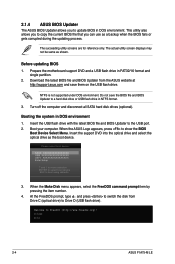
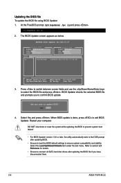
...Exit DATE: 06/03/2011 F1A75MLE.ROM File Info MODEL: F1A75-M LE Help Info VER: 0206 DATE: 01/18/11 [Enter] Select or Load [Tab] Switch [Up/Down/PageUp/PageDown/Home/End] Move [Esc] Exit [F2] Backup 2-2 ASUS F1A75-M LE Updating from file, then click Next. To update the ...BIOS using EZ Flash 2: 1. b. Locate the BIOS file from the ASUS website at www.asus.com. The ASUS Update utility is capable of the BIOS setup program. Go to the ...
...Exit DATE: 06/03/2011 F1A75MLE.ROM File Info MODEL: F1A75-M LE Help Info VER: 0206 DATE: 01/18/11 [Enter] Select or Load [Tab] Switch [Up/Down/PageUp/PageDown/Home/End] Move [Esc] Exit [F2] Backup 2-2 ASUS F1A75-M LE Updating from file, then click Next. To update the ...BIOS using EZ Flash 2: 1. b. Locate the BIOS file from the ASUS website at www.asus.com. The ASUS Update utility is capable of the BIOS setup program. Go to the ...
User Manual
Page 40
... USB XXXXXXXXXXXXXXXXX UEFI: XXXXXXXXXXXXXXXX Enter Setup ↑ and ↓ to move selection ENTER to select boot device ESC to the USB port. 2. C:\>d: D:\> 2-4 ASUS F1A75-M LE This utility also allows you to copy the current BIOS file that you to update BIOS in FAT32/16 format and single partition. 2. NTFS is...select the optical drive as the boot device. At the FreeDOS prompt, type d: and press to switch the disk from the ASUS website at http://support.asus.com and save the BIOS file and BIOS Updater to a hard disk drive or USB flash drive in DOS environment 1. Booting...
... USB XXXXXXXXXXXXXXXXX UEFI: XXXXXXXXXXXXXXXX Enter Setup ↑ and ↓ to move selection ENTER to select boot device ESC to the USB port. 2. C:\>d: D:\> 2-4 ASUS F1A75-M LE This utility also allows you to copy the current BIOS file that you to update BIOS in FAT32/16 format and single partition. 2. NTFS is...select the optical drive as the boot device. At the FreeDOS prompt, type d: and press to switch the disk from the ASUS website at http://support.asus.com and save the BIOS file and BIOS Updater to a hard disk drive or USB flash drive in DOS environment 1. Booting...
User Manual
Page 42
...BIOS Updater version 1.04 or later, the utility automatically exits to the DOS prompt after updating the BIOS file if you have disconnected them. 2-6 ASUS F1A75-M LE Select Yes and press . Restart your computer. Select the Load Optimized Defaults item under the Exit menu. D:\>bupdater /pc /g 2. Refer to ... drives after updating BIOS. • Ensure to load the BIOS default settings to section 2.9 Exit menu for DOS V1.07 Current ROM BOARD: F1A75-M LE VER: 0302 DATE: 06/03/2011 Update ROM BOARD: Unknown VER: Unknown DATE: Unknown PATH: A:\ A: F1A75M.ROM 4194304 2011-05-02 ...
...BIOS Updater version 1.04 or later, the utility automatically exits to the DOS prompt after updating the BIOS file if you have disconnected them. 2-6 ASUS F1A75-M LE Select Yes and press . Restart your computer. Select the Load Optimized Defaults item under the Exit menu. D:\>bupdater /pc /g 2. Refer to ... drives after updating BIOS. • Ensure to load the BIOS default settings to section 2.9 Exit menu for DOS V1.07 Current ROM BOARD: F1A75-M LE VER: 0302 DATE: 06/03/2011 Update ROM BOARD: Unknown VER: Unknown DATE: Unknown PATH: A:\ A: F1A75M.ROM 4194304 2011-05-02 ...
User Manual
Page 44
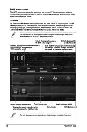
...program without saving the changes, saves the changes and resets the system, or enters the Advanced Mode EFI BIOS Utility - EZ Mode Tuesday [1/1/2008] F1A75-M LE BIOS Version : 0308 CPU Type : AMD Engineering Sample Total Memory : 1024 MB (DDR3 1333MHz) Exit/Advanced Mode Build Date : 06/13/2011....248V Q-Fan Control Quiet Performance Boot Priority Energy Saving Normal Use the mouse to drag or keyboard to navigate to the system. 2-8 ASUS F1A75-M LE You can change modes from the Exit menu or from the Exit/Advanced Mode button in section 2.7 Boot menu for entering the BIOS ...
...program without saving the changes, saves the changes and resets the system, or enters the Advanced Mode EFI BIOS Utility - EZ Mode Tuesday [1/1/2008] F1A75-M LE BIOS Version : 0308 CPU Type : AMD Engineering Sample Total Memory : 1024 MB (DDR3 1333MHz) Exit/Advanced Mode Build Date : 06/13/2011....248V Q-Fan Control Quiet Performance Boot Priority Energy Saving Normal Use the mouse to drag or keyboard to navigate to the system. 2-8 ASUS F1A75-M LE You can change modes from the Exit menu or from the Exit/Advanced Mode button in section 2.7 Boot menu for entering the BIOS ...

User Manual
Page 46
... bottom right corner of a menu screen when there are the navigation keys for the menu items. If an item is a brief description of options. 2-10 ASUS F1A75-M LE Use the navigation keys to display the other items (Ai Tweaker, Advanced, Monitor, Boot, Tool, and Exit) on the screen. Submenu items A greater than sign...
... bottom right corner of a menu screen when there are the navigation keys for the menu items. If an item is a brief description of options. 2-10 ASUS F1A75-M LE Use the navigation keys to display the other items (Ai Tweaker, Advanced, Monitor, Boot, Tool, and Exit) on the screen. Submenu items A greater than sign...
User Manual
Page 48
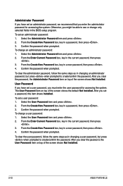
... an administrator password, but press when prompted to create/confirm the password. The User Password item on top of the screen shows Not Installed. 2-12 ASUS F1A75-M LE Confirm the password when prompted. From the Create New Password box, key in a new password, then press . 4.
... an administrator password, but press when prompted to create/confirm the password. The User Password item on top of the screen shows Not Installed. 2-12 ASUS F1A75-M LE Confirm the password when prompted. From the Create New Password box, key in a new password, then press . 4.

User Manual
Page 50
The values range from 90.0MHz to start automatic overclocking. 2-14 ASUS F1A75-M LE DRAM O.C. The valid value ranges vary according to your CPU model. 2.4.4 EPU Power Saving Mode [Disabled] Allows you to set power saving mode. Press and ...
The values range from 90.0MHz to start automatic overclocking. 2-14 ASUS F1A75-M LE DRAM O.C. The valid value ranges vary according to your CPU model. 2.4.4 EPU Power Saving Mode [Disabled] Allows you to set power saving mode. Press and ...
User Manual
Page 52
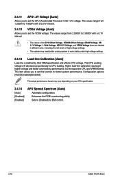
... you to set the APU (Accelerated Processor Unit) 1.2V voltage. 2.4.11 APU1.2V Voltage [Auto] Allows you to set this function for EMI control. 2-16 ASUS F1A75-M LE The values range from 2.5000V to 2.8000V with a 0.01V interval. 2.4.12 VDDA Voltage [Auto] Allows you to work stably under high voltage settings. 2.4.13 Load...
... you to set the APU (Accelerated Processor Unit) 1.2V voltage. 2.4.11 APU1.2V Voltage [Auto] Allows you to set this function for EMI control. 2-16 ASUS F1A75-M LE The values range from 2.5000V to 2.8000V with a 0.01V interval. 2.4.12 VDDA Voltage [Auto] Allows you to work stably under high voltage settings. 2.4.13 Load...


