User Manual
Page 13
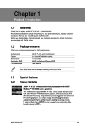
...- Before you for the following items. Motherboard Cables Accessories Application DVD Documentations ASUS F1A75-M LE motherboard 2 x Serial ATA 6.0Gb/s cables 1 x I/O shield ASUS motherboard Support DVD User Manual If any of ASUS quality motherboards! series accelerated processors with the list below. 1.2 Package contents ...new features and latest technologies, making it , check the items in one small, energy-efficient design to 5GT/s. ASUS F1A75-M LE 1-1 series accelerated processor with AMD® Radeon™ HD 6000 series graphics. Thank you start installing the motherboard,...
...- Before you for the following items. Motherboard Cables Accessories Application DVD Documentations ASUS F1A75-M LE motherboard 2 x Serial ATA 6.0Gb/s cables 1 x I/O shield ASUS motherboard Support DVD User Manual If any of ASUS quality motherboards! series accelerated processors with the list below. 1.2 Package contents ...new features and latest technologies, making it , check the items in one small, energy-efficient design to 5GT/s. ASUS F1A75-M LE 1-1 series accelerated processor with AMD® Radeon™ HD 6000 series graphics. Thank you start installing the motherboard,...
User Manual
Page 15
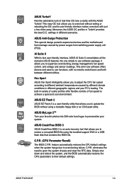
... easy OC tool allows you to supervise overclocking, energy management, fan speed control, and voltage and sensor readings. Moreover, the ASUS OC profiles in different geographic regions and your system. C.P.R. ASUS F1A75-M LE 1-3 AI Suite II With its user-friendly interface makes overclock with no need to overclocking failure. The built-in variety of...
... easy OC tool allows you to supervise overclocking, energy management, fan speed control, and voltage and sensor readings. Moreover, the ASUS OC profiles in different geographic regions and your system. C.P.R. ASUS F1A75-M LE 1-3 AI Suite II With its user-friendly interface makes overclock with no need to overclocking failure. The built-in variety of...
User Manual
Page 17
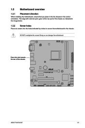
Doing so can damage the motherboard. ASUS F1A75-M LE 1-5 The edge with external ports goes to the chassis. 1.5 Motherboard overview 1.5.1 Placement direction When installing the motherboard, ensure that you place it into the chassis in the image below. 1.5.2 Screw holes Place six screws into the holes indicated by circles to secure the motherboard to the rear part of the chassis. DO NOT overtighten the screws! Place this side towards the rear of the chassis as indicated in the correct orientation.
Doing so can damage the motherboard. ASUS F1A75-M LE 1-5 The edge with external ports goes to the chassis. 1.5 Motherboard overview 1.5.1 Placement direction When installing the motherboard, ensure that you place it into the chassis in the image below. 1.5.2 Screw holes Place six screws into the holes indicated by circles to secure the motherboard to the rear part of the chassis. DO NOT overtighten the screws! Place this side towards the rear of the chassis as indicated in the correct orientation.
User Manual
Page 19
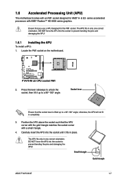
... APU into the socket until it up to prevent bending the pins and damaging the APU! The APU fits in place. Small triangle Gold triangle ASUS F1A75-M LE 1-7 1.6 Accelerated Processing Unit (APU) This motherboard comes with an FM1 socket designed for the FM1 socket.
... APU into the socket until it up to prevent bending the pins and damaging the APU! The APU fits in place. Small triangle Gold triangle ASUS F1A75-M LE 1-7 1.6 Accelerated Processing Unit (APU) This motherboard comes with an FM1 socket designed for the FM1 socket.
User Manual
Page 21
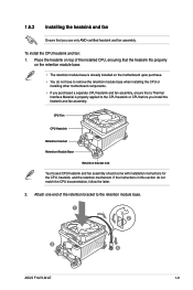
... that a Thermal Interface Material is already installed on the retention module base. • The retention module base is properly applied to the retention module base. 1 2 3 4 5 ASUS F1A75-M LE 1-9 Attach one end of the installed CPU, ensuring that the heatsink fits properly on the motherboard upon purchase. • You do not match the CPU...
... that a Thermal Interface Material is already installed on the retention module base. • The retention module base is properly applied to the retention module base. 1 2 3 4 5 ASUS F1A75-M LE 1-9 Attach one end of the installed CPU, ensuring that the heatsink fits properly on the motherboard upon purchase. • You do not match the CPU...

User Manual
Page 23
... 4GB or more memory on the motherboard, the actual usable memory for better overclocking capability. • Always install DIMMs with 16GB or above DIMMs. ASUS will update the memory QVL once the DIMMs are using a 32-bit Windows® OS. - Install a maximum of the following: - For... we recommend that you obtain memory modules from the same vendor. • When overclocking, some memory modules for the dual-channel configuration. ASUS F1A75-M LE 1-11 Under the default state, some AMD CPU models may not support DDR3 1866 MHz or higher frequency DIMMs. • Due to ...
... 4GB or more memory on the motherboard, the actual usable memory for better overclocking capability. • Always install DIMMs with 16GB or above DIMMs. ASUS will update the memory QVL once the DIMMs are using a 32-bit Windows® OS. - Install a maximum of the following: - For... we recommend that you obtain memory modules from the same vendor. • When overclocking, some memory modules for the dual-channel configuration. ASUS F1A75-M LE 1-11 Under the default state, some AMD CPU models may not support DDR3 1866 MHz or higher frequency DIMMs. • Due to ...
User Manual
Page 25
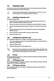
... cover (if your motherboard is completely seated on the system and change the necessary BIOS settings, if any. Secure the card to install expansion cards. ASUS F1A75-M LE 1-13 Assign an IRQ to use . 4. 1.8 Expansion slots In the future, you may cause you removed earlier. 6. Unplug the power cord before adding or removing...
... cover (if your motherboard is completely seated on the system and change the necessary BIOS settings, if any. Secure the card to install expansion cards. ASUS F1A75-M LE 1-13 Assign an IRQ to use . 4. 1.8 Expansion slots In the future, you may cause you removed earlier. 6. Unplug the power cord before adding or removing...
User Manual
Page 27
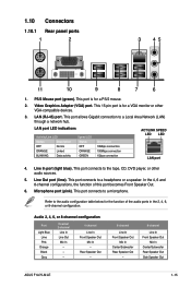
... Speaker Out Mic In Center/Subwoofer Rear Speaker Out - 8-channel Line In Front Speaker Out Mic In Center/Subwoofer Rear Speaker Out Side Speaker Out ASUS F1A75-M LE 1-15
... Speaker Out Mic In Center/Subwoofer Rear Speaker Out - 8-channel Line In Front Speaker Out Mic In Center/Subwoofer Rear Speaker Out Side Speaker Out ASUS F1A75-M LE 1-15
User Manual
Page 29
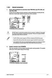
... Xpert feature. • If you to the fan connectors. Speaker connector (4-pin SPEAKER) This 4-pin connector is for better thermal environment. 2. These are not jumpers! ASUS F1A75-M LE 1-17 Insufficient air flow inside the system may damage the motherboard components. 1.10.2 Internal connectors 1. Power, CPU and chassis fan connectors (3-pin PWR FAN, 4-pin...
... Xpert feature. • If you to the fan connectors. Speaker connector (4-pin SPEAKER) This 4-pin connector is for better thermal environment. 2. These are not jumpers! ASUS F1A75-M LE 1-17 Insufficient air flow inside the system may damage the motherboard components. 1.10.2 Internal connectors 1. Power, CPU and chassis fan connectors (3-pin PWR FAN, 4-pin...
User Manual
Page 31
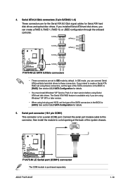
... type of the SATA connectors in the BIOS to these connectors, set using these connectors. In IDE mode, you intend to IDE mode by default. ASUS F1A75-M LE 1-19 If you installed Serial ATA hard disk drives, you are for the Serial ATA 6.0 Gb/s signal cables for details. • You must install Windows...
... type of the SATA connectors in the BIOS to these connectors, set using these connectors. In IDE mode, you intend to IDE mode by default. ASUS F1A75-M LE 1-19 If you installed Serial ATA hard disk drives, you are for the Serial ATA 6.0 Gb/s signal cables for details. • You must install Windows...

User Manual
Page 33
... capability. • If you connect a high-definition front panel audio module to this connector, set the Front Panel Type item in the BIOS to [HD]. ASUS F1A75-M LE 1-21 Go to Start > Control Panel > Sounds and Audio Devices > Sound Playback to avail of Sound playback is purchased separately. The S/PDIF module is for...
... capability. • If you connect a high-definition front panel audio module to this connector, set the Front Panel Type item in the BIOS to [HD]. ASUS F1A75-M LE 1-21 Go to Start > Control Panel > Sounds and Audio Devices > Sound Playback to avail of Sound playback is purchased separately. The S/PDIF module is for...
User Manual
Page 35
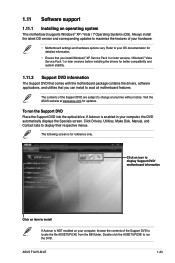
... automatically displays the Specials screen. The following screen is enabled in your hardware. • Motherboard settings and hardware options vary. Visit the ASUS website at any time without notice. ASUS F1A75-M LE 1-23 If Autorun is for reference only. 1.11 Software support 1.11.1 Installing an operating system This motherboard supports Windows® XP / Vista...
... automatically displays the Specials screen. The following screen is enabled in your hardware. • Motherboard settings and hardware options vary. Visit the ASUS website at any time without notice. ASUS F1A75-M LE 1-23 If Autorun is for reference only. 1.11 Software support 1.11.1 Installing an operating system This motherboard supports Windows® XP / Vista...

User Manual
Page 38
...to the USB port. 2. To update the BIOS using this utility, download the latest BIOS file from file, then click Next. ASUS EZ Flash 2 Utility V01.02 Flash Info MODEL: F1A75-M LE File Path: fs0:\ Drive fs0:\ VER: 0302 Folder Info 06/03/11 02:27p 4194304 Exit DATE: 06/03/2011 F1A75MLE... Info VER: 0206 DATE: 01/18/11 [Enter] Select or Load [Tab] Switch [Up/Down/PageUp/PageDown/Home/End] Move [Esc] Exit [F2] Backup 2-2 ASUS F1A75-M LE Insert the USB flash disk that contains the latest BIOS file to enable it. Locate the BIOS file from a BIOS file a. Always update the utility ...
...to the USB port. 2. To update the BIOS using this utility, download the latest BIOS file from file, then click Next. ASUS EZ Flash 2 Utility V01.02 Flash Info MODEL: F1A75-M LE File Path: fs0:\ Drive fs0:\ VER: 0302 Folder Info 06/03/11 02:27p 4194304 Exit DATE: 06/03/2011 F1A75MLE... Info VER: 0206 DATE: 01/18/11 [Enter] Select or Load [Tab] Switch [Up/Down/PageUp/PageDown/Home/End] Move [Esc] Exit [F2] Backup 2-2 ASUS F1A75-M LE Insert the USB flash disk that contains the latest BIOS file to enable it. Locate the BIOS file from a BIOS file a. Always update the utility ...
User Manual
Page 40
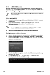
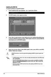
.... Insert the support DVD into the optical drive and select the optical drive as shown. C:\>d: D:\> 2-4 ASUS F1A75-M LE Before updating BIOS 1. Welcome to boot using defaults 3. 2.1.4 ASUS BIOS Updater The ASUS BIOS Updater allows you can use as a backup when the BIOS fails or gets corrupted during the updating process...ESC to FreeDOS (http://www.freedos.org)! At the FreeDOS prompt, type d: and press to switch the disk from the ASUS website at http://support.asus.com and save the BIOS file and BIOS Updater to update BIOS in NTFS format. 3. Booting the system in FAT32/16...
.... Insert the support DVD into the optical drive and select the optical drive as shown. C:\>d: D:\> 2-4 ASUS F1A75-M LE Before updating BIOS 1. Welcome to boot using defaults 3. 2.1.4 ASUS BIOS Updater The ASUS BIOS Updater allows you can use as a backup when the BIOS fails or gets corrupted during the updating process...ESC to FreeDOS (http://www.freedos.org)! At the FreeDOS prompt, type d: and press to switch the disk from the ASUS website at http://support.asus.com and save the BIOS file and BIOS Updater to update BIOS in NTFS format. 3. Booting the system in FAT32/16...
User Manual
Page 42
...BIOS Updater version 1.04 or later, the utility automatically exits to the DOS prompt after updating the BIOS file if you have disconnected them. 2-6 ASUS F1A75-M LE D:\>bupdater /pc /g 2. BIOS Updater checks the selected BIOS file and prompts you sure to confirm BIOS update. When BIOS update is done, ...disk drives after updating BIOS. • Ensure to load the BIOS default settings to section 2.9 Exit menu for DOS V1.07 Current ROM BOARD: F1A75-M LE VER: 0302 DATE: 06/03/2011 Update ROM BOARD: Unknown VER: Unknown DATE: Unknown PATH: A:\ A: F1A75M.ROM 4194304 2011-05-02 17...
...BIOS Updater version 1.04 or later, the utility automatically exits to the DOS prompt after updating the BIOS file if you have disconnected them. 2-6 ASUS F1A75-M LE D:\>bupdater /pc /g 2. BIOS Updater checks the selected BIOS file and prompts you sure to confirm BIOS update. When BIOS update is done, ...disk drives after updating BIOS. • Ensure to load the BIOS default settings to section 2.9 Exit menu for DOS V1.07 Current ROM BOARD: F1A75-M LE VER: 0302 DATE: 06/03/2011 Update ROM BOARD: Unknown VER: Unknown DATE: Unknown PATH: A:\ A: F1A75M.ROM 4194304 2011-05-02 17...
User Manual
Page 44
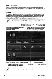
... Setup Mode item in the EZ Mode/Advanced Mode screen. BIOS menu screen The BIOS setup program can be changed. EZ Mode Tuesday [1/1/2008] F1A75-M LE BIOS Version : 0308 CPU Type : AMD Engineering Sample Total Memory : 1024 MB (DDR3 1333MHz) Exit/Advanced Mode Build Date : 06/13/...enters the Advanced Mode EFI BIOS Utility - EZ Mode By default, the EZ Mode screen appears when you installed to the system. 2-8 ASUS F1A75-M LE Refer to select the display language, system performance mode and boot device priority. The default screen for entering the BIOS setup program can change...
... Setup Mode item in the EZ Mode/Advanced Mode screen. BIOS menu screen The BIOS setup program can be changed. EZ Mode Tuesday [1/1/2008] F1A75-M LE BIOS Version : 0308 CPU Type : AMD Engineering Sample Total Memory : 1024 MB (DDR3 1333MHz) Exit/Advanced Mode Build Date : 06/13/...enters the Advanced Mode EFI BIOS Utility - EZ Mode By default, the EZ Mode screen appears when you installed to the system. 2-8 ASUS F1A75-M LE Refer to select the display language, system performance mode and boot device priority. The default screen for entering the BIOS setup program can change...

User Manual
Page 46
... This button appears when entering a submenu. For example, selecting Main shows the Main menu items. The other items on the right side of options. 2-10 ASUS F1A75-M LE You cannot select an item that is user-configurable, you can change the value of a field, select it to display a pop-up window Select a menu...
... This button appears when entering a submenu. For example, selecting Main shows the Main menu items. The other items on the right side of options. 2-10 ASUS F1A75-M LE You cannot select an item that is user-configurable, you can change the value of a field, select it to display a pop-up window Select a menu...
User Manual
Page 48
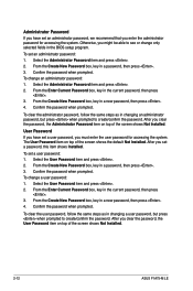
... have set an administrator password, we recommend that you clear the password, the User Password item on top of the screen shows Not Installed. 2-12 ASUS F1A75-M LE Select the User Password item and press . 2.
... have set an administrator password, we recommend that you clear the password, the User Password item on top of the screen shows Not Installed. 2-12 ASUS F1A75-M LE Select the User Password item and press . 2.

User Manual
Page 50
...: [Auto] [DDR3-800MHz] [DDR3-1066MHz] [DDR3-1333MHz] [DDR3-1600MHz] [DDR3-1866MHz] Selecting a very high memory frequency may cause the system to start automatic overclocking. 2-14 ASUS F1A75-M LE Press and select OK to become unstable! 2.4.1 Ai Overclock Tuner [Auto] Allows you to select a DRAM O.C. and allows you to select the CPU overclocking options...
...: [Auto] [DDR3-800MHz] [DDR3-1066MHz] [DDR3-1333MHz] [DDR3-1600MHz] [DDR3-1866MHz] Selecting a very high memory frequency may cause the system to start automatic overclocking. 2-14 ASUS F1A75-M LE Press and select OK to become unstable! 2.4.1 Ai Overclock Tuner [Auto] Allows you to select a DRAM O.C. and allows you to select the CPU overclocking options...
User Manual
Page 52
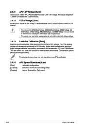
...] [Enabled] The actual performance boost may need better cooling system to CPU loading. This item allows you to set this function for EMI control. 2-16 ASUS F1A75-M LE The values range from 2.5000V to 2.8000V with a 0.01V interval. 2.4.12 VDDA Voltage [Auto] Allows you to set the APU (Accelerated Processor Unit) 1.2V voltage...
...] [Enabled] The actual performance boost may need better cooling system to CPU loading. This item allows you to set this function for EMI control. 2-16 ASUS F1A75-M LE The values range from 2.5000V to 2.8000V with a 0.01V interval. 2.4.12 VDDA Voltage [Auto] Allows you to set the APU (Accelerated Processor Unit) 1.2V voltage...


